EP0315123A2 - Bohrwerkzeug - Google Patents
Bohrwerkzeug Download PDFInfo
- Publication number
- EP0315123A2 EP0315123A2 EP88118178A EP88118178A EP0315123A2 EP 0315123 A2 EP0315123 A2 EP 0315123A2 EP 88118178 A EP88118178 A EP 88118178A EP 88118178 A EP88118178 A EP 88118178A EP 0315123 A2 EP0315123 A2 EP 0315123A2
- Authority
- EP
- European Patent Office
- Prior art keywords
- pressure piece
- drill shaft
- inclined surface
- undercut
- cutting edge
- Prior art date
- Legal status (The legal status is an assumption and is not a legal conclusion. Google has not performed a legal analysis and makes no representation as to the accuracy of the status listed.)
- Granted
Links
- 238000005553 drilling Methods 0.000 title claims abstract description 44
- 230000008878 coupling Effects 0.000 claims abstract description 32
- 238000010168 coupling process Methods 0.000 claims abstract description 32
- 238000005859 coupling reaction Methods 0.000 claims abstract description 32
- 238000005520 cutting process Methods 0.000 claims abstract description 30
- 239000000428 dust Substances 0.000 description 9
- 230000000875 corresponding effect Effects 0.000 description 6
- 230000000694 effects Effects 0.000 description 2
- 238000000605 extraction Methods 0.000 description 2
- 238000005495 investment casting Methods 0.000 description 2
- 239000000463 material Substances 0.000 description 2
- 230000035515 penetration Effects 0.000 description 2
- 230000002411 adverse Effects 0.000 description 1
- 238000006073 displacement reaction Methods 0.000 description 1
- 238000009826 distribution Methods 0.000 description 1
- 238000005516 engineering process Methods 0.000 description 1
- 230000002349 favourable effect Effects 0.000 description 1
- 230000001771 impaired effect Effects 0.000 description 1
- 238000004519 manufacturing process Methods 0.000 description 1
- 239000002184 metal Substances 0.000 description 1
- 238000000034 method Methods 0.000 description 1
- 238000010422 painting Methods 0.000 description 1
- 230000002093 peripheral effect Effects 0.000 description 1
- 238000003825 pressing Methods 0.000 description 1
- 230000003313 weakening effect Effects 0.000 description 1
Images
Classifications
-
- F—MECHANICAL ENGINEERING; LIGHTING; HEATING; WEAPONS; BLASTING
- F16—ENGINEERING ELEMENTS AND UNITS; GENERAL MEASURES FOR PRODUCING AND MAINTAINING EFFECTIVE FUNCTIONING OF MACHINES OR INSTALLATIONS; THERMAL INSULATION IN GENERAL
- F16D—COUPLINGS FOR TRANSMITTING ROTATION; CLUTCHES; BRAKES
- F16D3/00—Yielding couplings, i.e. with means permitting movement between the connected parts during the drive
- F16D3/02—Yielding couplings, i.e. with means permitting movement between the connected parts during the drive adapted to specific functions
-
- B—PERFORMING OPERATIONS; TRANSPORTING
- B23—MACHINE TOOLS; METAL-WORKING NOT OTHERWISE PROVIDED FOR
- B23B—TURNING; BORING
- B23B51/00—Tools for drilling machines
- B23B51/0018—Drills for enlarging a hole
- B23B51/0045—Drills for enlarging a hole by expanding or tilting the toolhead
-
- B—PERFORMING OPERATIONS; TRANSPORTING
- B25—HAND TOOLS; PORTABLE POWER-DRIVEN TOOLS; MANIPULATORS
- B25G—HANDLES FOR HAND IMPLEMENTS
- B25G3/00—Attaching handles to the implements
- B25G3/38—Hinged, pivoted, swivelling, or folding joints
Definitions
- the invention relates to a drilling tool for producing undercuts in non-continuous cylindrical pilot bores, with a drill shaft approximately corresponding in diameter to the diameter of the pilot bore, which is connected at its tip to a pressure piece and can be supported via an inclined surface on the former and one radially above it
- Such a drilling tool is known from EP-A1-0 242 638.
- the pressure piece is fastened radially movably directly on the inclined surface of the drill shaft tip.
- Such a pressure piece can be pulled out of the bore and can be used in many ways.
- the radially movable attachment ensures that the desired radial advance of one or more side cutting edges is generated in a simple manner, as in the case of a loose pressure piece.
- the guide groove is arranged at the tip of the drill shaft and the coupling projection on the pressure piece.
- the invention has for its object to improve a drilling tool of the type mentioned so that the connection strength between the drill shaft tip and the pressure piece is sufficient even in rough operation, so the connection is sufficiently stable.
- the coupling projection is located at the tip of the drill shaft, so that there is no recess for receiving a coupling projection in the interior of the drill shaft.
- the coupling engagement between the undercut guide groove of the drill shaft tip and the coupling projection has limited movement play axially and / or transversely to the guide groove.
- the limited range of motion is present so that drilling dust cannot adversely affect the radial mobility between the pressure piece and the drill shaft tip.
- a pressure piece In order to be able to connect the pressure piece to the drill shaft in a non-detachable manner in a simple manner, a pressure piece has such a guide groove which has at least one integrally formed transverse projection on one groove end and at least one deformation region on the other groove end.
- the drilling shank in the area between the side cutting edge and its upper, connection-side end has a friction at the outer bore wall that at least reduces the outer radius.
- Warped or curved pre-bores deviate to a small extent from the cylinder shape desired per se and offer the mechanical drive of the boring tool an increased resistance with a corresponding overload of the boring tool itself and the parts driving it.
- the reduction in the outer radius avoids such an oversize load in the majority of cases, where the delay of the pilot hole is limited and it is guaranteed that the undercut is fully pronounced.
- the weakening of the diameter is possible without impairing the stability of the drilling tool, so that the mechanical connection between the two parts that takes place via the coupling projection of the drilling shaft and the guide groove of the pressure piece is also correspondingly stable.
- the drill shaft has a bore running longitudinally up to the connection-side end, it is advantageous if the bore opens radially in the direction of rotation in front of the side cutting edge and, if necessary, also diagonally opposite.
- Such an arrangement of the bore ensures that the resulting drilling dust can be sucked off directly at the point at which it is formed and also avoids the disadvantage that exists only with an axial dust extraction hole that the dust is sucked off between the curved sliding surface of the pressure piece and the correspondingly curved inclined surface of the drill shaft tip should be what would have the risk of impairing the suction and the sliding effect.
- wear on the coupling elements due to the effect of the dust on painting is avoided.
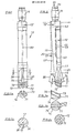
- the drilling tool 10 shown in FIGS. 1, 2 consists essentially of a drilling shaft 12 and a pressure piece 14.
- the drilling shaft 12 has a tip 11 and a drive connection 18, which can be designed, for example, as a thread.
- the outermost drive-side end of the drill shaft 12 is designed as an axial pressurizing surface 54, with which the drill shaft 12 is subjected to axial pressurization in the direction of arrow 35, e.g. B. is supported by a hammer drill on this or its receptacle.
- the cylindrical pilot hole 17 is shown in dash-dot lines. It can be seen that the drill shaft 12 has at its upper end a diameter 62 corresponding approximately to the diameter of the pilot hole 17. Otherwise, the detailed design of the drill shaft 12 can be seen from FIGS. 3 a to 3 d of EP-A1-0 242 638.
- the drill shaft 12 On the pressure piece 14 facing tip 11 of the drill shaft 12 has a side cutting edge 15 which protrudes radially beyond its outer circumference and is arranged such that in the coaxial position shown in FIG. 2 between the pilot hole 17 and the drill shaft 12 can produce undercut 36 shown in dash-dotted lines.
- the side cutting edge 15 is provided with a cutting edge 26 inclined to the drill shaft tip 11. Since the drilling tool 10 rotates clockwise, the drill shaft tip 11 is cut out in the area 38 in front of the side cutting edge 15 and is supported in the area 39 for driving it by the material of the drill shaft 12.
- the drill shaft 12 is provided with a flattened circumference 16 which extends from the drill shaft tip 11 to the drive connection 18. From Fig. 2 it can be seen that this flattening takes place evenly or at the same angle to the drill shaft axis 25. The angle is illustrated in FIG. 2 by reference number 60. The flattening results in side edges 40.
- the inclined surface 13 is inclined at approximately 40 ° to 70 °, preferably 65 °, to the drill shaft axis 25 in the axial direction of the arrow 35, that is to say inclined towards the pressure piece 14.
- the inclined surface 13 is approximately parallel to the diagonally opposite surface section of the sole. Axial loading of the drill shaft 12 results in a radial propulsion of the side cutting edge 15 via the inclined surface 13 to produce the undercut 36.
- the inclined surface 13 of the adjacent pressure piece surface is spatially adapted, which results from FIG. 1.
- the side cutting edge 15 is arranged without overlap with respect to the inclined surface 13, that is to say it is arranged horizontally higher than the uppermost region of the inclined surface 13, which results in particular from FIG. 2.
- This design of the drilling tool 10 serves in particular for stability in the area of the drill shaft tip 11, which is heavily stressed by the striking advance of the drilling tool 10.
- the attachment of the side cutting edge 15, for example a hard metal plate soldered into the drill shaft 12, is also less stressed by the above-described design of the drilling tool 10.
- a pressure piece 14 is fastened so that there is permanent cohesion in the axial direction.
- the drill shaft 12 can be axially inserted into and pulled out of the pilot hole 17 without any manipulations having to be carried out beforehand and / or afterwards with regard to the introduction of the pressure piece or its whereabouts in or in the pilot hole 17.
- the pressure piece 14 is intended for permanent use in connection with the drill shaft 12 due to its permanent attachment to the drill shaft tip 11 and must therefore be particularly resistant.
- it is preferably designed as a tempered forged part. An investment casting with corresponding properties can also be used.
- the assembly of the pressure piece 14 with the inclined surface 13 is such that both can move relative to one another in the radial direction.
- the pressure piece 14 has an undercut guide groove 71 which, according to the figures, is parallel to the inclined surface, that is to say has the same inclination towards the drill shaft axis as the inclined surface 13.
- This guide groove 71 engages Coupling projection 72 of the drill shaft tip 11, preferably axially positively.
- This coupling projection 72 is formed like a strip and at the same time undercut, so that the two coupling parts 71, 72 have to be pushed together for assembly in the plane of FIG. 2.
- the coupling piece 14 has a sliding surface 73.
- This sliding surface 73 extends in the radial direction of movement in which the relative displacements between the pressure piece 14 and the drill shaft tip 11 take place.
- the sliding surface 73 is curved transversely thereto and the figures show that the inclined surface 13 is curved accordingly.
- the coupling projection 72 has limited movement axially but also radially in the guide groove 71, accordingly the pressure piece 14 and the drill shaft tip 11 can move relative to one another. This movement play ensures that drilling dust arising on the sliding surface 73 during the drilling process does not lead to excessive stress on the coupling parts 71, 72 or to their jamming.
- the coupling parts 71, 72 are also relieved by the fact that the rotational driving forces occurring when the drill shaft 12 is driven in rotation are transmitted directly from the drill bit 11 via its inclined surface 13 to the curved sliding surface 73 of the pressure piece 14.
- the maximum outer diameter of the pressure piece 14 is somewhat smaller than the diameter of the pilot hole 17.
- the guide groove 71 is machined into the pressure piece 14, while the coupling projection 72 is fastened to the drill shaft tip 11 with a web 78 in such a way that its inclined surface 13 is divided into two equally large sections, each of which has an almost quarter-circular cross section. Accordingly, the coupling projection 72 is practically flush with the lowermost or outermost edges of the drill shaft tip 11. Accordingly, the sliding surface 73 of the coupling piece 14 is practically semicircular in cross section and provided with mutually parallel surface lines. In particular, from the comparison of FIG. 26 of EP-A1-0 242 638 and FIG. 2a it can be seen that the sliding surface 73 in the pressure piece 14 present here is considerably enlarged, which is due to the larger axial extent required to enclose the coupling projection 72 is conditional.
- the coupling projection 72 is inserted into the guide groove 71 until it bears against the transverse projections 75 thereof. The edges 76 are then deformed, thereby achieving the desired permanent assembly.
- the drill shaft 12 has a reduced outer radius in its circumferential region opposite the previously described flattening 16, which has an approximately semicircular cross section. This results from the recess shown in FIGS. 1, 2 of this peripheral drill shaft area between the diameter 62 at the upper, connection-side end 12 'of the drill shaft 12 and its projection 77 in the vicinity of the side cutting edge 15 because these two, i.e. the diameter 62 and the projection 77 have approximately a pre-bore radius.
- the projection 77 is dimensioned so that it comes to rest on the inner wall 17 ⁇ when the undercut 36 is completed by the side cutting edge 15.
- the projection 77 serves to maintain the exact central position of the drill shaft 12 after completion of the undercut 36, if the drill shaft has the above-described reduced outer radius or a free space to the inner wall 17 ⁇ of the pilot hole 17.
- the drill shaft 12 also has a bore 33 through which the drilling dust can be suctioned off.
- the bore 33 has two outlet channels 79, 80 which each slope from the pressure piece 14 to the connection-side end 12 'of the drill shaft 12 to facilitate the extraction of drilling dust.
- the opening channel 79 opens radially in the direction of rotation in front of the side cutting edge 15, see FIG. 1.
- the opening channel 80 is only present as required and is arranged diagonally opposite the side cutting edge 15 in such a way that it sucks off dust originating from a higher area of the side cutting edge 15.
- the drilling tool 10 is operated by first inserting the pressure piece 14 into the cylindrical pilot hole 17 and pressing it against the base of the pilot hole 17 by the drilling shaft 12.
- the inserted into the pilot hole 17 drill shaft lies with its flattened outer circumference 16 on the inner wall 17 ⁇ of the pilot hole 17 because the radially projecting side cutting edge 15 projects over the outer circumference of the drilling shaft 12 because of the depth of the undercut 36. If the inclined surface 13 of the drill shaft 12 is seated on the pressure piece 14, the drilling tool 10 can be axially loaded, whereby a radial force component is generated, namely in the direction of the projection of the side cutting edge 15.
- the cutting edge 26 digs with its cutting edge 26 in the the inner wall 17 ⁇ forming material and produces the ring groove-like undercut 36 shown in FIG. 2 when the drilling shaft 12 rotates.
- the drilling shaft 12 shifts axially inward into the pilot hole 17, its inclined surface 13 on the pressure piece 14 slipped.
- the drill shaft 12 performs circular wobbling movements when the machine is driven. He is supported in the beginning of the pilot hole 17 with the end 12 '. In this area, the drill shaft 12 can be tapered crowned.
Landscapes
- Engineering & Computer Science (AREA)
- Mechanical Engineering (AREA)
- General Engineering & Computer Science (AREA)
- Processing Of Stones Or Stones Resemblance Materials (AREA)
- Drilling Tools (AREA)
- Cutting Tools, Boring Holders, And Turrets (AREA)
- Drilling And Boring (AREA)
Abstract
Description
- Die Erfindung bezieht sich auf ein Bohrwerkzeug zur Herstellung von Hinterschneidungen in nicht durchgehenden zylindrischen Vorbohrungen, mit einem im Durchmesser dem Durchmesser der Vorbohrung etwa entsprechenden Bohrschaft, der an seiner Spitze mit einem Druckstück verbunden und über eine Schrägfläche an ersterem abstützbar ist sowie eine radial über seinen Außenumfang vorstehende, bei seiner Axialbeaufschlagung die Hinterschneidung erzeugende Seitenschneide aufweist, der gegenüber der Bohrschaft in einem dessen Einführen in die Vorbohrung gestattendem Maße abgeflacht ist, wobei das Druckstück direkt an der Schrägfläche der Bohrschaftspitze mittels einer schrägflächenparallelen hinterschnittenen Führungsnut radialbeweglich befestigt ist, in die ein hinterschnittleistenförmiger Kupplungsvorsprung axial formschlüssig eingreift, und wobei das Druckstück eine quer zur Radialbewegungsrichtung der Seitenschneide gewölbte Gleitfläche aufweist, auf der die ebenfalls gewölbte Schrägfläche der Bohrschaftsspitze abstützbar ist.
- Ein derartiges Bohrwerkzeug ist aus der EP-A1-0 242 638 bekannt. Bei einem solchen Bohrwerkzeug ist es besonders vorteilhaft, daß das Druckstück direkt an der Schrägfläche der Bohrschaftspitze radialbeweglich befestigt ist. Ein solches Druckstück kann aus der Bohrung herausgezogen werden und ist vielfach zu verwenden. Die radialbewegliche Befestigung gewährleistet, daß in einfacher Weise, wie bei einem losen Druckstück, der gewünschte Radialvortrieb einer oder mehrerer Seitenschneiden erzeugt wird. Bei dem bekannten Bohrwerkzeug ist die Führungsnut an der Spitze des Bohrschafts und der Kupplungsvorsprung am Druckstück angeordnet. Bei dieser Ausgestaltung kann zwar eine universellere Verwendbarkeit des Bohrschafts dadurch erreicht werden, daß in seine Führungsnut unterschiedlich gestaltete Kupplungsvorsprünge oder unterschiedlich gestaltete Druckstücke eingesetzt werden, jedoch sind die Belastung des Kupplungsvorsprungs und der Schaftspitze im rauhen Betrieb unter Umständen so groß, daß die Haltbarkeit der axial formschlüssigen Verbindung beeinträchtigt wird. Es kommt beispielsweise in gewissen Anwendungsfällen zum Aufweiten der Schaftspitze.
- Demgegenüber liegt der Erfindung die Aufgabe zugrunde, ein Bohrwerkzeug der eingangs genannten Art so zu verbessern, daß die Verbindungsfestigkeit zwischen der Bohrschaftspitze und dem Druckstück auch im rauhen Betrieb ausreicht, die Verbindung also hinreichend standfest ist.
- Diese Aufgabe wird dadurch gelöst, daß der Kupplungsvorsprung an der Bohrschaftspitze angebracht ist und die Führungsnut sich in einem Druckstück mit halbkreisartiger Wölbung seiner Gleitfläche befindet.
- Für die Erfindung ist wesentlich, daß sich der Kupplungsvorsprung an der Bohrschaftspitze befindet, so daß eine Vertiefung zur Aufnahme eines Kupplungsvorsprungs im Inneren des Bohrschafts entfällt. Durch das Geringerhalten der Eingriffstiefe des Druckstücks in die Bohrschaftspitze wird die Stabilität der Bohrschaftspitze entsprechend verstärkt. Zugleich ist die Gleitfläche infolge ihrer halbkreisartigen Wölbung größer bzw. die auf diese Wölbung entfallende Eingriffstiefe ist größer, so daß eine verbesserte Drehmitnahme des Druckstücks erfolgt.
- Der Kupplungseingriff zwischen der hinterschnittenen Führungsnut der Bohrschaftspitze und dem Kupplungsvorsprung weist axial und/oder quer zur Führungsnut begrenztes Bewegungsspiel auf. Das begrenzte Bewegungsspiel ist vorhanden, damit anfallender Bohrstaub die Radialbeweglichkeit zwischen Druckstück und Bohrschaftspitze nicht beeinträchtigen kann.
- Um das Druckstück mit dem Bohrschaft auf einfacher Weise unlösbar verbinden zu können, hat ein Druckstück eine solche Führungsnut, die am einen Nutende mindestens einen angeformten Quervorsprung und am anderen Nutende mindestens einen Verformungsbereich aufweist.
- Bei der Anwendung des Bohrwerkzeugs in verzogenen bzw. krummen Bohrungen ist es zweckmäßig, daß der Bohrschaft im Bereich zwischen der Seitenschneide und seinem oberen, anschlußseitigen Ende einen Reibung an der Vorbohrungswand zumindest verringernden Außenradius aufweist. Verzogene bzw. krumme Vorbohrungen weichen in geringem Maße von der an sich erwünschten Zylinderform ab und bieten dem maschinellen Antrieb des Bohrwerkzeugs einen erhöhten Widerstand mit entsprechender Überbelastung des Bohrwerkzeugs selbst und der es antreibenden Teile. Die Verringerung des Außenradius vermeidet eine solche Überbe lastung in den überwiegenden Fällen, in denen sich der Verzug der Vorbohrung in Grenzen hält und es ist gewährleistet, daß der Hinterschnitt voll ausgeprägt ist. Die Durchmesserschwächung ist ohne Beeinträchtigung der Stabilität des Bohrwerkzeugs möglich, so daß auch die über den Kupplungsvorsprung des Bohrschafts und die Führungsnut des Druckstücks erfolgende mechanische Verbindung zwischen beiden Teilen entsprechend stabil ist.
- Zweckmäßig ist oberhalb der Seitenschneide ein bei fertiggestellter Hinterschneidung an der Vorbohrungswand anliegender Schaftabschnitt vorhanden, der dazu beitragen kann, die exakte Axialendlage des Bohrschafts zu sichern, so daß eine Überbeanspruchung der aus dem Kupplungsvorsprung und der Führungsnut bestehenden mechanische Verbindung zwischen dem Bohrschaft und dem Druckstück im Sinne einer vergrößerten Standfestigkeit erreicht wird.
- Hat der Bohrschaft eine bis zum anschlußseitigen Ende längsdurchlaufende Bohrung, so ist es vorteilhaft, wenn die Bohrung radial in Drehrichtung vor der Seitenschneide und bedarfsweise auch diagonal gegenüber mündet. Eine derartige Anordnung der Bohrung sorgt dafür, daß der anfallende Bohrstaub direkt an der Stelle seines Entstehens abgesaugt werden kann und vermeidet außerdem den bei einer lediglich axialen Staubabsaugbohrung gegebenen Nachteil, daß der Staub zwischen der gewölbten Gleitfläche des Druckstücks und der entsprechend gewölbten Schrägfläche der Bohrschaftspitze abgesaugt werden müßte, was die Gefahr der Beeinträchtigung der Saugwirkung und der Gleitwirkung hätte. Zusätzlich wird Verschleiß an den Kupplungselementen durch Malwirkung des Staubs vermieden.
- Die Erfindung wird anhand von in der Zeichnung dargestellten Ausführungsbeispielen näher erläutert. Es zeigt:
- Fig. 1 eine Seitenansicht eines Bohrers,
- Fig. 1a das dem Bohrer der Fig. 1 zugeordnete und in entsprechender Ansicht dargestellte, teilweise geschnitte Druckstück,
- Fig. 1b den Schnitt B-B der Fig. 1,
- Fig. 2 eine um 90° gedrehte Darstellung des Bohrwerkzeugs der Fig. 1,
- Fig. 2a eine entsprechend um 90° gedrehte Seitenansicht des Druckstücks der Fig. 1a,
- Fig. 2b eine um 90° nach unten gekippte Aufsicht auf das Druckstück der Fig. 2a, und
- Fig. 2c die Schnittdarstellung C-C der Fig. 2.
- Das in den Fig. 1, 2 dargestellte Bohrwerkzeug 10 besteht im wesentlichen aus einem Bohrschaft 12 und einem Druckstück 14. Der Bohrschaft 12 hat eine Spitze 11 und einen Antriebsanschluß 18, der beispielsweise als Gewinde ausgebildet werden kann. Das äußerste antriebsseitige Ende des Bohrschafts 12 ist als Axialbeaufschlagungsfläche 54 ausgebildet, mit der sich der Bohrschaft 12 bei in Richtung des Pfeiles 35 erfolgender Axialbeaufschlagung z. B. durch eine Hammerbohrmaschine an dieser bzw. deren Aufnahme abstützt.
- In Fig. 2 ist die zylindrische Vorbohrung 17 strichpunktiert eingezeichnet. Es ist ersichtlich, daß der Bohrschaft 12 an seinem oberen Ende einen etwa dem Durchmesser der Vorbohrung 17 entsprechenden Durchmesser 62 aufweist. Im übrigen ist die nähere Ausbildung des Bohrschaftes 12 aus den Fig. 3 a bis 3 d der EP-A1-0 242 638 ersichtlich.
- An der dem Druckstück 14 zugewendeten Spitze 11 hat der Bohrschaft 12 eine Seitenschneide 15, die radial über seinen Außenumfang vorsteht und so angeordnet ist, daß sich bei der in Fig. 2 dargestellten gleichachsigen Lage zwischen der Vorbohrung 17 und dem Bohrschaft 12 die strichpunktiert dargestellte Hinterschneidung 36 erzeugen läßt. Die Seitenschneide 15 ist mit einer zu der Bohrschaftspitze 11 geneigten Schneidkante 26 versehen. Da die Drehung des Bohrwerkzeugs 10 im Uhrzeigersinn erfolgt, ist die Bohrschaftspitze 11 im Bereich 38 vor der Seitenschneide 15 ausgenommen und im Bereich 39 zu ihrem Antrieb durch Werkstoff des Bohrschafts 12 abgestützt. Der Bohrschaft 12 ist mit einem abgeflachten Umfang 16 versehen, der sich von der Bohrschaftspitze 11 bis zum Antriebsanschluß 18 erstreckt. Aus Fig. 2 ist ersichtlich, daß diese Abflachung gleichmäßig bzw. mit demselben Winkel zur Bohrschaftachse 25 erfolgt. Der Winkel ist in Fig. 2 durch das Bezugszeichen 60 veranschaulicht. Durch die Abflachung ergeben sich Seitenkanten 40.
- An der Bohrschaftspitze 11 ist eine Schrägfläche 13 vorhanden, mit der sich der Bohrschaft 12 auf dem Druckstück 14 abstützen kann, wenn er in der Richtung des Pfeils 35 in die Vorbohrung 17 hineingeschoben und damit das Druckstück 14 gegen die nicht dargestellte Sohle der Vorbohrung 17 gepreßt wird. Die Schrägfläche 13 ist etwa unter 40° bis 70°, vorzugsweise 65° zur Bohrschaftachse 25 in Axialbeaufschlagungsrichtung des Pfeils 35 geneigt, also dem Druckstück 14 zugeneigt. Dabei ist die Schrägfläche 13 etwa parallel dem diagonal gegenüberliegenden Flächenabschnitt der Sohle. Eine Axialbeaufschlagung des Bohrschaftes 12 ergibt über die Schrägfläche 13 einen radialen Vortrieb der Seitenschneide 15 zur Herstellung der Hinterschneidung 36.
- Um die Flächenpressung zwischen der Schrägfläche 13 und dem Druckstück 14 gering zu halten, ist die Schrägfläche 13 der benachbarten Druckstückfläche räumlich angepaßt, was sich aus Fig. 1 ergibt.
- Die Seitenschneide 15 ist bezüglich der Schrägfläche 13 überlappungsfrei angeordnet, daß heißt, sie ist horizontal gesehen höher angeordnet, als der oberste Bereich der Schrägfläche 13, was sich insbesondere aus Fig. 2 ergibt. Diese Ausbildung des Bohrwerkzeugs 10 dient insbesondere der Stabilität im Bereich der Bohrschaftspitze 11, welche durch den schlagenden Vorschub des Bohrwerkzeugs 10 stark beansprucht wird. Auch die Befestigung der Seitenschneide 15, beispielsweise eines in den Bohrschaft 12 eingelöteten Hartmetallplättchens, wird durch die vorbeschriebene Ausbildung des Bohrwerkzeugs 10 weniger beansprucht.
- An der Bohrschaftspitze 11 bzw. an dessen Schrägfläche 13 ist ein Druckstück 14 so befestigt, daß in axialer Richtung ein dauerhafter Zusammenhalt gegeben ist. Infolgedessen kann der Bohrschaft 12 axial in die Vorbohrung 17 hineingesteckt und aus dieser herausgezogen werden ohne daß vorher und/oder nachher etwaige Manipulationen bezüglich der Einbringung des Druckstücks bzw. dessen Verbleib in die bzw. in der Vorbohrung 17 durchgeführt werden müßten. Das Druckstück 14 ist infolge seiner dauerhaften Befestigung an der Bohrschaftspitze 11 zur ständigen Verwendung in Verbindung mit dem Bohrschaft 12 bestimmt und muß daher besonders widerstandsfähig sein. Es ist infolgedessen vorzugsweise als vergütetes Schmiedeteil ausgebildet. Auch ein Feingußteil mit entsprechenden Eigenschaften ist verwendbar.
- Der Zusammenbau des Druckstücks 14 mit der Schrägfläche 13 ist dergestalt, daß sich beide in radialer Richtung relativ zueinander bewegen können. Hierzu hat das Druckstück 14 eine hinterschnittene Führungsnut 71, die gemäß den Figuren schrägflächenparallel ist, also dieselbe Neigung gegen die Bohrschaftachse aufweist, wie die Schrägfläche 13. In diese Führungsnut 71 greift ein Kupplungsvorsprung 72 der Bohrschaftspitze 11 ein, und zwar vorzugsweise axial formschlüssig. Dieser Kupplungsvorsprung 72 ist leistenartig ausgebildet und dabei zugleich hinterschnitten, so daß die beiden Kupplungsteile 71, 72 zum Zusammenbau in der Darstellungsebene der Fig. 2 zusammengeschoben werden müssen.
- Desweiteren ist aus Fig. 2a ersichtlich, daß das Kupplungsstück 14 eine Gleitfläche 73 aufweist. Diese Gleitfläche 73 verläuft in der Radialbewegungsrichtung, in der die Relativverschiebungen zwischen dem Druckstück 14 und der Bohrschaftspitze 11 stattfinden. Quer dazu ist die Gleitfläche 73 gewölbt und die Figuren zeigen, daß die Schrägfläche 13 entsprechend gewölbt ist.
- Die Figuren zeigen nicht, daß der Kupplungsvorsprung 72 axial, aber auch radial ein begrenztes Bewegungsspiel in der Führungsnut 71 aufweist, demgemäß sich das Druckstück 14 und die Bohrschaftspitze 11 relativ zueinander bewegen können. Durch dieses Bewegungsspiel wird gewährleistet, daß beim Bohrvorgang entstehender Bohrstaub auf der Gleitfläche 73 nicht zu einer Überbeanspruchung der Kupplungsteile 71, 72 bzw, zu deren Verklemmen führt. Die Kupplungsteile 71, 72 werden darüberhinaus dadurch entlastet, daß die beim Drehantrieb des Bohrschafts 12 auftretenden Drehmitnahmekräfte direkt von der Bohrspitze 11 über deren Schrägfläche 13 auf die gewölbte Gleitfläche 73 des Druckstücks 14 übertragen werden.
- Aufgrund der Radialbewegung der Bohrschaftspitze 11 und der damit verbundenen Axialbelastung des Druckstücks 14 ist nicht auszuschließen, daß dieses eine kreiselartige Drehbewegung ausführt. Um diese Bewegung zu erleichtern, ist der maximale Außendurchmesser des Druckstücks 14 etwas kleiner, als der Durchmesser der Vorbohrung 17.
- Die Führungsnut 71 ist in das Druckstück 14 eingearbeitet, während der Kupplungsvorsprung 72 mit einem Steg 78 an der Bohrschaftspitze 11 derart befestigt ist, daß dessen Schrägfläche 13 in zwei gleichgroße Abschnitte unterteilt ist, die jeweils nahezu viertelkreisförmigen Querschnitt haben. Dementsprechend liegt der Kupplungsvorsprung 72 praktisch bündig mit den untersten bzw. äußersten Kanten der Bohrschaftsspitze 11. Dementsprechend ist die Gleitfläche 73 des Kupplungsstücks 14 praktisch halbkreisartig im Querschnitt und mit einander parallelen Mantellinien versehen. Insbesondere aus dem Vergleich der Fig. 26 der EP-A1-0 242 638 und der Fig. 2a ist ersichtlich, daß die Gleitfläche 73 beim hier vorliegenden Druckstück 14 erheblich vergrößert ist, was durch die größere, zur Umfassung des Kupplungsvorsprungs 72 erforderliche axiale Erstreckung bedingt ist. Dadurch ergibt sich eine günstige Verteilung der Drehmitnahmekräfte auf das Druckstück 14 ohne Belastung des Kupplungsvorsprungs 72 und mit erheblich verminderter Belastung der Bohrschaftspitze 11. Es ist ersichtlich, daß der Kupplungsvorsprung 72 geringfügig über die untersten Enden der Bohrschaftspitze 11 vorstehen, so daß die Führungsnut 71 entsprechend tief in das Druckstück 14 eingearbeitet ist.
- Zum Zusammenbauen des Druckstücks 14 mit dem Bohrschaft 12 wird der Kupplungsvorsprung 72 in die Führungsnut 71 gesteckt, bis er an deren Quervorsprüngen 75 anliegt. Sodann werden die Kanten 76 verformt, wodurch der gewünschte dauerhafte Zusammenbau erreicht wird.
- Die Fig. 1, 2 zeigen einen Rohling des Bohrerschafts, der als Feingußteil ausgebildet ist, ebenso wie das Druckstück 14, um deren für ihren axialen Zusammenhalt erforderliche Formgebung herstellungstechnisch einfach zu ermöglichen. Das zeigt sich daran, daß das anschlußseitige Ende bzw. der Antriebsanschluß 18 noch nicht mit dem an sich vorgesehenen Gewindeanschluß versehen ist. Gleichwohl ist aber aus darstellerischen Gründen bereits eine Seitenschneide 15 dargestellt, die der Herstellung einer Hinterschneidung 36 in der Innenwand 17˝ der Vorbohrung 17 dient, was in Fig. 13 strichpunktiert dargestellt ist.
- Aus beiden Darstellungen ist ersichtlich, daß der Bohrschaft 12 in seinem der vorbeschriebenen Abflachung 16 gegenüberliegenden Umfangsbereich, der etwa halbkreisförmigen Querschnitt hat, einen verringerten Außenradius aufweist. Das ergibt sich aus dem aus den Fig. 1, 2 ersichtlichen Rücksprung dieses peripheren Bohrschaftbereichs zwischen dem Durchmesser 62 am oberen, anschlußseitigen Ende 12′ des Bohrschafts 12 und dessen Vorsprung 77 in der Nähe der Seitenschneide 15, weil diese beiden, also der Durchmesser 62 und der Vorsprung 77, etwa Vorbohrungsradius aufweisen. Der durch diese Ausgestaltung des Bohrschafts 12 ermöglichte Freiraum zur Innenwand 17˝ der Vorbohrung 17 gestattet die problemlose Anwendung des Bohrwerkzeugs 10 auch dann, wenn die Vorbohrung 17 krumm ist, also ihre Innenwand 17˝ Vorsprünge aufweist, welche die erforderliche Drehbewegung des Bohrschafts 12 behindern würden.
- Der Vorsprung 77 ist so bemessen, daß er an der Innenwand 17˝ zur Anlage kommt, wenn die Hinterschneidung 36 durch die Seitenschneide 15 fertiggestellt ist. Der Vorsprung 77 dient der Einhaltung der exakten zentrischen Lage des Bohrschafts 12 nach Fertigstellung der Hinterschneidung 36, wenn der Bohrschaft den vorbeschriebenen verringerten Außenradius bzw. einen Freiraum zur Innenwand 17˝ der Vorbohrung 17 aufweist.
- Der Bohrschaft 12 weist noch eine Bohrung 33 auf, durch die der anfallende Bohrstaub abgesaugt werden kann.
- Im Bereich der Bohrspitze 11 hat die Bohrung 33 zwei Mündungskanäle 79, 80 die jeweils vom Druckstück 14 zum anschlußseitigen Ende 12′ des Bohrschafts 12 hin geneigt verlaufen, um das Absaugen von Bohrstaub zu erleichtern. Der Mündungskanal 79 mündet radial in Drehrichtung vor der Seitenschneide 15, vergl. Fig. 1. Der Mündungskanal 80 ist lediglich bedarfsweise vorhanden und diagonal gegenüber der Seitenschneide 15 so angeordnet, daß er aus einem höheren Bereich der Seitenschneide 15 stammenden Staub absaugt.
- Das Bohrwerkzeug 10 wird betrieben, indem zunächst das Druckstück 14 in die zylindrische Vorbohrung 17 hineingesteckt und von dem Bohrschaft 12 gegen die Sohle der Vorbohrung 17 gedrückt wird. Der in die Vorbohrung 17 eingeschobene Bohrschaft liegt während des Einschiebens mit seinem abgeflachten Außenumfang 16 an der Innenwand 17˝ der Vorbohrung 17 an, weil die wegen der Tiefe der Hinterschneidung 36 radial vorspringende Seitenschneide 15 über den Außenumfang des Bohrschafts 12 vorspringt. Wenn die Schrägfläche 13 des Bohrschafts 12 auf dem Druckstück 14 aufsitzt, kann das Bohrwerkzeug 10 axial beaufschlagt werden, wodurch eine radiale Kraftkomponente erzeugt wird, und zwar in Richtung des Vorsprungs der Seitenschneide 15. Infolgedessen gräbt sich die Seitenschneide 15 mit ihrer Schneidkante 26 in den die Innenwand 17˝ bildenden Werkstoff ein und erzeugt bei Drehung des Bohrschafts 12 die aus Fig. 2 ersichtlichen ringnutartige Hinterschneidung 36. Während des radialen Eindringens der Seitenschneide 15 verlagert sich der Bohrschaft 12 axial einwärts in die Vorbohrung 17, wobei seine Schrägfläche 13 auf dem Druckstück 14 abgleitet. Während des axialen und radialen Eindringens vollführt der Bohrschaft 12 bei maschinellem Antrieb kreisende Taumelbewegungen. Dabei ist er im Anfangsbereich der Vorbohrung 17 mit dem Ende 12′ abgestützt. In diesem Bereich kann der Bohrschaft 12 ballig verjüngt sein.
Claims (6)
Applications Claiming Priority (2)
| Application Number | Priority Date | Filing Date | Title |
|---|---|---|---|
| DE3737746 | 1987-11-06 | ||
| DE19873737746 DE3737746A1 (de) | 1986-12-03 | 1987-11-06 | Bohrwerkzeug |
Publications (3)
| Publication Number | Publication Date |
|---|---|
| EP0315123A2 true EP0315123A2 (de) | 1989-05-10 |
| EP0315123A3 EP0315123A3 (en) | 1990-07-04 |
| EP0315123B1 EP0315123B1 (de) | 1992-08-12 |
Family
ID=6339964
Family Applications (1)
| Application Number | Title | Priority Date | Filing Date |
|---|---|---|---|
| EP88118178A Expired - Lifetime EP0315123B1 (de) | 1987-11-06 | 1988-11-01 | Bohrwerkzeug |
Country Status (4)
| Country | Link |
|---|---|
| EP (1) | EP0315123B1 (de) |
| AT (1) | ATE79316T1 (de) |
| DE (1) | DE3873691D1 (de) |
| ES (1) | ES2034107T3 (de) |
Cited By (1)
| Publication number | Priority date | Publication date | Assignee | Title |
|---|---|---|---|---|
| CN108788238A (zh) * | 2018-08-02 | 2018-11-13 | 中北大学 | 一种带有径向可倾瓦块的深孔加工智能钻杆系统 |
Family Cites Families (3)
| Publication number | Priority date | Publication date | Assignee | Title |
|---|---|---|---|---|
| DE8610234U1 (de) * | 1986-04-15 | 1987-08-20 | Eischeid, Karl, 5250 Engelskirchen | Bohrwerkzeug |
| ES2012067B3 (es) * | 1986-04-15 | 1990-03-01 | Karl Eischeid | Herramienta para taladrar |
| DE8632363U1 (de) * | 1986-12-03 | 1988-05-11 | Eischeid, Karl, 5250 Engelskirchen | Bohrwerkzeug |
-
1988
- 1988-11-01 DE DE8888118178T patent/DE3873691D1/de not_active Expired - Lifetime
- 1988-11-01 AT AT88118178T patent/ATE79316T1/de not_active IP Right Cessation
- 1988-11-01 ES ES198888118178T patent/ES2034107T3/es not_active Expired - Lifetime
- 1988-11-01 EP EP88118178A patent/EP0315123B1/de not_active Expired - Lifetime
Cited By (2)
| Publication number | Priority date | Publication date | Assignee | Title |
|---|---|---|---|---|
| CN108788238A (zh) * | 2018-08-02 | 2018-11-13 | 中北大学 | 一种带有径向可倾瓦块的深孔加工智能钻杆系统 |
| CN108788238B (zh) * | 2018-08-02 | 2023-09-15 | 中北大学 | 一种带有径向可倾瓦块的深孔加工智能钻杆系统 |
Also Published As
| Publication number | Publication date |
|---|---|
| DE3873691D1 (de) | 1992-09-17 |
| ATE79316T1 (de) | 1992-08-15 |
| EP0315123B1 (de) | 1992-08-12 |
| EP0315123A3 (en) | 1990-07-04 |
| ES2034107T3 (es) | 1993-04-01 |
Similar Documents
| Publication | Publication Date | Title |
|---|---|---|
| DE2945766C2 (de) | Bohrkrone und Bohrwerkzeug mit einer solchen Bohrkrone | |
| DE102010025653B4 (de) | Rotations-Schneidwerkzeug | |
| DE2709830C3 (de) | Zentrumsbohrer zur Bearbeitung von Holz, Kunststoff u.dgl. | |
| WO1990000957A1 (de) | Einrichtung an handwerkzeugmaschinen zur drehmomentübertragung | |
| EP0043000A1 (de) | Hinterschnitt-Bohrwerkzeug | |
| DE19526686B4 (de) | Mehrstufenbohrer | |
| DE3507817A1 (de) | Bohrer zur erzeugung einer hinterschneidung in einer bohrung | |
| EP0551795B1 (de) | Werkzeug zum Schlagbohren und Meisseln und Werkzeugaufnahme für diese Werkzeuge | |
| EP0242638B1 (de) | Bohrwerkzeug | |
| DE2331467B2 (de) | Vorrichtung zum Ausbohren einer Bohrung mit einem zylindrischen und einem konischen Bereich | |
| DE9104326U1 (de) | Bohrvorrichtung zum Herstellen von Bohrungen mit Hinterschneidungen | |
| DE102007038254A1 (de) | Bauteil mit Verbindungseinrichtung und Herstellungsverfahren | |
| DE10359854A1 (de) | Zylinderkopfbohrer mit Hartmetallschneiden und Kunststoffschaft | |
| EP3656494A1 (de) | Stufenbohrer | |
| DE3118691C2 (de) | ||
| DE3025890A1 (de) | Bohrer fuer bohrhaemmer, insbes. zum bohren in gestein, beton o.dgl. | |
| DE4441820B4 (de) | Bohr- und/oder Schlaghammer | |
| EP0315123B1 (de) | Bohrwerkzeug | |
| DE3528173A1 (de) | Werkzeug und verfahren zum bohren eines hinterstochenen loches | |
| EP0791423B1 (de) | Bohrerhaltevorrichtung mit einem Bohrer | |
| EP0170877A1 (de) | Offenend-Spinnrotor und Verfahren zu seiner Herstellung | |
| DE3620389C2 (de) | ||
| DE3530296A1 (de) | Vorrichtung zum herstellen von wandausnehmungen | |
| DD236487A5 (de) | Werkzeug und verfahren zum bohren eines hinterstochenen loches | |
| DE10213024B4 (de) | Handwerkzeug und Messer zum Entgraten |
Legal Events
| Date | Code | Title | Description |
|---|---|---|---|
| PUAI | Public reference made under article 153(3) epc to a published international application that has entered the european phase |
Free format text: ORIGINAL CODE: 0009012 |
|
| AK | Designated contracting states |
Kind code of ref document: A2 Designated state(s): AT BE CH DE ES FR GB GR IT LI LU NL SE |
|
| PUAL | Search report despatched |
Free format text: ORIGINAL CODE: 0009013 |
|
| AK | Designated contracting states |
Kind code of ref document: A3 Designated state(s): AT BE CH DE ES FR GB GR IT LI LU NL SE |
|
| 17P | Request for examination filed |
Effective date: 19901010 |
|
| 17Q | First examination report despatched |
Effective date: 19910708 |
|
| GRAA | (expected) grant |
Free format text: ORIGINAL CODE: 0009210 |
|
| AK | Designated contracting states |
Kind code of ref document: B1 Designated state(s): AT BE CH DE ES FR GB GR IT LI LU NL SE |
|
| PG25 | Lapsed in a contracting state [announced via postgrant information from national office to epo] |
Ref country code: SE Free format text: THE PATENT HAS BEEN ANNULLED BY A DECISION OF A NATIONAL AUTHORITY Effective date: 19920812 Ref country code: GR Free format text: LAPSE BECAUSE OF FAILURE TO SUBMIT A TRANSLATION OF THE DESCRIPTION OR TO PAY THE FEE WITHIN THE PRESCRIBED TIME-LIMIT Effective date: 19920812 |
|
| REF | Corresponds to: |
Ref document number: 79316 Country of ref document: AT Date of ref document: 19920815 Kind code of ref document: T |
|
| GBT | Gb: translation of ep patent filed (gb section 77(6)(a)/1977) | ||
| REF | Corresponds to: |
Ref document number: 3873691 Country of ref document: DE Date of ref document: 19920917 |
|
| ITF | It: translation for a ep patent filed | ||
| ET | Fr: translation filed | ||
| PG25 | Lapsed in a contracting state [announced via postgrant information from national office to epo] |
Ref country code: LU Free format text: LAPSE BECAUSE OF NON-PAYMENT OF DUE FEES Effective date: 19921130 |
|
| REG | Reference to a national code |
Ref country code: ES Ref legal event code: FG2A Ref document number: 2034107 Country of ref document: ES Kind code of ref document: T3 |
|
| PLBE | No opposition filed within time limit |
Free format text: ORIGINAL CODE: 0009261 |
|
| STAA | Information on the status of an ep patent application or granted ep patent |
Free format text: STATUS: NO OPPOSITION FILED WITHIN TIME LIMIT |
|
| 26N | No opposition filed | ||
| PGFP | Annual fee paid to national office [announced via postgrant information from national office to epo] |
Ref country code: GB Payment date: 19961023 Year of fee payment: 9 Ref country code: BE Payment date: 19961023 Year of fee payment: 9 |
|
| PGFP | Annual fee paid to national office [announced via postgrant information from national office to epo] |
Ref country code: CH Payment date: 19961029 Year of fee payment: 9 |
|
| PGFP | Annual fee paid to national office [announced via postgrant information from national office to epo] |
Ref country code: ES Payment date: 19961112 Year of fee payment: 9 |
|
| PGFP | Annual fee paid to national office [announced via postgrant information from national office to epo] |
Ref country code: AT Payment date: 19961114 Year of fee payment: 9 |
|
| PGFP | Annual fee paid to national office [announced via postgrant information from national office to epo] |
Ref country code: FR Payment date: 19961127 Year of fee payment: 9 |
|
| PGFP | Annual fee paid to national office [announced via postgrant information from national office to epo] |
Ref country code: NL Payment date: 19961130 Year of fee payment: 9 |
|
| PG25 | Lapsed in a contracting state [announced via postgrant information from national office to epo] |
Ref country code: GB Free format text: LAPSE BECAUSE OF NON-PAYMENT OF DUE FEES Effective date: 19971101 Ref country code: AT Free format text: LAPSE BECAUSE OF NON-PAYMENT OF DUE FEES Effective date: 19971101 |
|
| PG25 | Lapsed in a contracting state [announced via postgrant information from national office to epo] |
Ref country code: ES Free format text: LAPSE BECAUSE OF NON-PAYMENT OF DUE FEES Effective date: 19971102 |
|
| PG25 | Lapsed in a contracting state [announced via postgrant information from national office to epo] |
Ref country code: LI Free format text: LAPSE BECAUSE OF NON-PAYMENT OF DUE FEES Effective date: 19971130 Ref country code: FR Free format text: THE PATENT HAS BEEN ANNULLED BY A DECISION OF A NATIONAL AUTHORITY Effective date: 19971130 Ref country code: CH Free format text: LAPSE BECAUSE OF NON-PAYMENT OF DUE FEES Effective date: 19971130 Ref country code: BE Free format text: LAPSE BECAUSE OF NON-PAYMENT OF DUE FEES Effective date: 19971130 |
|
| BERE | Be: lapsed |
Owner name: EISCHEID KARL Effective date: 19971130 |
|
| PG25 | Lapsed in a contracting state [announced via postgrant information from national office to epo] |
Ref country code: NL Free format text: LAPSE BECAUSE OF NON-PAYMENT OF DUE FEES Effective date: 19980601 |
|
| GBPC | Gb: european patent ceased through non-payment of renewal fee |
Effective date: 19971101 |
|
| REG | Reference to a national code |
Ref country code: CH Ref legal event code: PL |
|
| NLV4 | Nl: lapsed or anulled due to non-payment of the annual fee |
Effective date: 19980601 |
|
| REG | Reference to a national code |
Ref country code: FR Ref legal event code: ST |
|
| PGFP | Annual fee paid to national office [announced via postgrant information from national office to epo] |
Ref country code: DE Payment date: 19991119 Year of fee payment: 12 |
|
| PG25 | Lapsed in a contracting state [announced via postgrant information from national office to epo] |
Ref country code: DE Free format text: LAPSE BECAUSE OF NON-PAYMENT OF DUE FEES Effective date: 20010801 |
|
| REG | Reference to a national code |
Ref country code: ES Ref legal event code: FD2A Effective date: 19981212 |
|
| PG25 | Lapsed in a contracting state [announced via postgrant information from national office to epo] |
Ref country code: IT Free format text: LAPSE BECAUSE OF NON-PAYMENT OF DUE FEES;WARNING: LAPSES OF ITALIAN PATENTS WITH EFFECTIVE DATE BEFORE 2007 MAY HAVE OCCURRED AT ANY TIME BEFORE 2007. THE CORRECT EFFECTIVE DATE MAY BE DIFFERENT FROM THE ONE RECORDED. Effective date: 20051101 |