EP0315345A2 - Elektrische Verbinder - Google Patents
Elektrische Verbinder Download PDFInfo
- Publication number
- EP0315345A2 EP0315345A2 EP88309901A EP88309901A EP0315345A2 EP 0315345 A2 EP0315345 A2 EP 0315345A2 EP 88309901 A EP88309901 A EP 88309901A EP 88309901 A EP88309901 A EP 88309901A EP 0315345 A2 EP0315345 A2 EP 0315345A2
- Authority
- EP
- European Patent Office
- Prior art keywords
- contact members
- terminal
- contact
- members
- insulating body
- Prior art date
- Legal status (The legal status is an assumption and is not a legal conclusion. Google has not performed a legal analysis and makes no representation as to the accuracy of the status listed.)
- Granted
Links
Images


Classifications
-
- H—ELECTRICITY
- H01—ELECTRIC ELEMENTS
- H01R—ELECTRICALLY-CONDUCTIVE CONNECTIONS; STRUCTURAL ASSOCIATIONS OF A PLURALITY OF MUTUALLY-INSULATED ELECTRICAL CONNECTING ELEMENTS; COUPLING DEVICES; CURRENT COLLECTORS
- H01R4/00—Electrically-conductive connections between two or more conductive members in direct contact, i.e. touching one another; Means for effecting or maintaining such contact; Electrically-conductive connections having two or more spaced connecting locations for conductors and using contact members penetrating insulation
- H01R4/24—Connections using contact members penetrating or cutting insulation or cable strands
- H01R4/2416—Connections using contact members penetrating or cutting insulation or cable strands the contact members having insulation-cutting edges, e.g. of tuning fork type
- H01R4/2445—Connections using contact members penetrating or cutting insulation or cable strands the contact members having insulation-cutting edges, e.g. of tuning fork type the contact members having additional means acting on the insulation or the wire, e.g. additional insulation penetrating means, strain relief means or wire cutting knives
-
- H—ELECTRICITY
- H01—ELECTRIC ELEMENTS
- H01R—ELECTRICALLY-CONDUCTIVE CONNECTIONS; STRUCTURAL ASSOCIATIONS OF A PLURALITY OF MUTUALLY-INSULATED ELECTRICAL CONNECTING ELEMENTS; COUPLING DEVICES; CURRENT COLLECTORS
- H01R4/00—Electrically-conductive connections between two or more conductive members in direct contact, i.e. touching one another; Means for effecting or maintaining such contact; Electrically-conductive connections having two or more spaced connecting locations for conductors and using contact members penetrating insulation
- H01R4/24—Connections using contact members penetrating or cutting insulation or cable strands
- H01R4/2416—Connections using contact members penetrating or cutting insulation or cable strands the contact members having insulation-cutting edges, e.g. of tuning fork type
- H01R4/242—Connections using contact members penetrating or cutting insulation or cable strands the contact members having insulation-cutting edges, e.g. of tuning fork type the contact members being plates having a single slot
- H01R4/2425—Flat plates, e.g. multi-layered flat plates
- H01R4/2429—Flat plates, e.g. multi-layered flat plates mounted in an insulating base
- H01R4/2433—Flat plates, e.g. multi-layered flat plates mounted in an insulating base one part of the base being movable to push the cable into the slot
Definitions
- This invention relates to insulation displacement members and electrical connectors.
- insulation displacement terminals are used. Insulation displacement terminals of various constructions are well known. In use of such terminals, an insulated conductor is forced down between two cantilever spring contact members. This movement displaces insulation from around the conductor so that the conductor comes into electrical contact with each of the contact members. It is conventional to provide cutting edges in the contact members for the purpose of cutting into the insulation. However, it is not unknown for the cutting edges to cut through the insulation and into the conductor itself leading to eventual conductor breakage. U.S. Patents 3521221 issued July 21, 1970 and 4002391 issued January 11, 1972 describe examples of such terminals.
- Patent 4682835 performs satisfactorily over a wide range of temperatures for the various sizes of conductor, certain problems may exist when connecting larger diameter conductors having thick insulation into the terminal at particularly low temperatures. It has been found in some instances that these low temperatures produce a hardening of the insulation material such that the cutting edges of contact members of the terminal may not cut entirely through the insulation thereby producing an unsatisfactory electrical path between the terminal and the conductor.
- terminal members as described in U.S. Patent 4682835 are useful in electrical connector constructions which have minimal outside dimension requirements to enable such connectors to be assembled together with high density in certain situations.
- An example of such an electrical connector is as described in British Patent Application No. 2172650A published October 15, 1986 in the name of G. Debortoli, et al and in the corresponding U.S. Patent 4652071 granted March 24, 1987.
- connectors are used for connecting drop wires to a customer's premises from a distribution cable and are closely located together to enable them to be mounted within a suitable housing carried, for instance, upon a mounting pole or carried by a cable supporting strand.
- Patent 4682835 are used in such connectors, then clearly there is little clearance between the terminals and inside surfaces of the connector housing. Hence, if the cantilever members of the terminal are forced apart further than desired by uncut hardened insulation on a conductor, the contact members may interfere with the closing of the connector during downward movement of a closure member onto a connector body whereby complete closure of the connector may be impossible. Damage may also result to the contact members or the connector body and total lack of contact with the conductor itself.
- the present invention seeks to provide an electrical connector which will overcome the above problems.
- the present invention also provides an electrical connector incorporating such an insulation displacement terminal member.
- the present invention provides an electrical connector having an insulating body, a closure member and an insulation displacement terminal member, the terminal member having two cantilever spring contact members extending upwardly from a base and having spaced apart and opposing inner edges to define a conductor receiving slot between the contact members and having free ends with insulation cutting edges, the terminal member locatable in an operative position with its base within the insulating body, the closure member movable into a position to close the insualting body and having passage means for guidance of an electrical conductor and free ends of the contact members into a wire terminal position characterized in that each contact member has an outward projection of its outer edge in a position spaced from the base and from its free end, the projection located within the insulating body with the terminal member in the operative position, and the projections acting against the insulating body to stiffen the contact members during movement apart of their free ends so as to prevent engagement of the free ends with sides of the passage means.
- the projections are of convex curvature so that they may produce a rolling action upon the wall of the cavity of the body of the connector and also, preferably, the projections should be disposed between the upwardly inclined outer edges of the lower portions and the upwardly and outwardly inclined outer edges of the upper portions of the contact members.
- an insulation displacement terminal member 10 is of the construction described in U.S. Patent 4682835 granted July 28, 1987 to S. Aujla, et al.
- the terminal member 10 comprises a base 12 from which a terminal comprising two cantilever spring contact members 14 extend upwardly.
- the terminal member is formed from flat strip conductor material with the contact members 14 extending widthwise in a common plane away from a slot 16 formed between them.
- Each contact member has upper and lower portions 18 and 20, respectively.
- the slot 16 is wider at a lower slot portion 16a than at an upper slot portion 16b which lies between the upper portions 18 of the contact members.
- Outer edges 22 of the lower portions of the contact members extend upwardly from the base while extending inwardly of the terminal so as to progressively decrease the width of the lower portions as shown.
- the outer edges 24 of the upper portions 18 of the contact members extend upwardly from the edges 22 while being inclined outwardly of the terminal so as effectively to produce a slight widening of the upper portions towards their upper ends.
- Upper edges 26 of the contact members are inclined downwardly towards the slot 16 and meet inner edges 28 of the contact members to produce cutting edges 30 one at each side of the opening to the slot 16.
- One of the contact members is provided with an inwardly extending protrusion 32 which is disposed above the wider part 16a of the slot.
- This protrusion engages the opposite inner edge 28 of the other contact member and is formed so as to apply pressure against that edge in the opening direction of the contact members so as to pre-stress them. This is to ensure that the contact members will apply a sufficient gripping load upon a conductor of small diameter, e.g. 26 gauge, when such a conductor is placed between them.
- this protrusion is formed by swaging as described in U.S. Patent 4682835 mentioned above.
- the upper portions of the contact members are thinner than the lower portions. This is to reduce the load necessary to force a conductor between the contact members while ensuring that the lower parts of the terminal are of sufficient cross-sectional area to produce the required resilient bending characteristics to enable it to be used with conductors over a wide range of gauges, e.g. between 18 and 26 AWG.
- the upper portions are reduced in thickness in two stages. A first reduction in thickness occurs slightly above the protrusion 32, as can be seen from Figure 1, and a further reduction in thickness occurs above an inclined edge 34, this further reduction extending over a substantially triangular region 35 to the upper edge 26 of each upper portion.
- the reduced thickness above the edge 34 provides a better cutting action during initial insertion of a drop wire particularly one of heavy gauge such as 18 AWG.
- the terminal members 10 also have relatively short cantilever spring contact members 36 of a lower insulation displacement terminal extending downwardly from the base 12.
- a housing comprises an insulating body 42 and a closure member 44.
- the insulating body 42 has a base 46 with two cavities 48 for accommodating spaced-apart terminal members 10 (see Figure 4).
- Towards the bottom of the base 46 are disposed two inlet passages 50 for insulated conductors 52 of a distribution cable (not shown).
- the terminal members are disposed in the cavities 48 with their upper portions 18 extending upwardly beyond the base and lying between surrounding walls 55 of the body.
- the closure 44 is provided with two spaced-apart passages 56 for acceptance of insulated drop wires into wire terminal positions within the closure member.
- the closure member is provided with an entry passage 58 and a exit passage 60 which are aligned across the passage 56 and are aligned with the upper portions of the terminal members 10.
- the closure member 44 is movable between a retracted and upper position, shown in Figure 2, and a lower fully retained or operative position, shown in Figure 3, by rotation of a screw 62.
- This screw is held rotatably captive by the closure member and received in a screw-threaded hole passing through the base of the body.
- the conductors 52 may be connected to the lower contact members 36 of the terminals before inserting the drop wires. This is performed by moving the closure member downwards as described in the previous patents so that it engages means for urging the contact members downwardly from a detent or retracted position (shown in Figure 2 and the left-hand side of Figures 4 and 5) and into its operative position (shown in Figure 3 and the right-hand side of Figures 4 and 5).
- the urging means may be in the form of a block 64 inserted into the wider parts 16a of the slots.
- the underside of the closure member engages these blocks 64 and forces the terminal members 10 downwardly so that the conductors 52 become engaged between the lower contact members 36 while their insulation is stripped away to provide electrical contact with the terminal members 10.
- the closure member is then raised to enable the drop wires 66 to be inserted into the passages 56 and across the tops of the terminal members 10 substantially in alignment with the slots 16. This is shown at the left-hand side of Figure 5.
- the closure member is again moved downwards to its retained position with the intention of forcing the drop wires down between the upper portions of the terminal members so as to cut through the insulation on the cutting edges 30 and to force the conductors into the upper portions 16b of the slots.
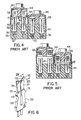
- the closure member 44 is in its upper retracted position with two heavily insulated 18 gauge drop wires 66 disposed in position in the passages 56 ready for connection to the terminal members 10.
- the insulation may be sufficiently stiff and hard to resist cutting action by the cutting edges 30 of the terminal members whereby the cutting edges only pass partially through the insulation.
- a terminal member 70 of an electrical connector 74 ( Figure 8) according to an embodiment of the invention is basically of the same structure as the terminal member 10 described above.
- the same reference numerals will be used for identical parts.
- the terminal member 70 differs basically from the prior terminal member however in that it has two outward projections 72 extending one from the outer edge of each contact member at a position spaced from the base. These projections may be located at any position spaced from the base to provide additional stiffness to the contact members and further resist their outward movement, as will be described.
- each projection it is preferred, and as shown in the embodiment, for the projections to be disposed between the upwardly and inwardly inclined outer edges 22 of the lower portions and the upwardly and outwardly inclined outer edges 24 of the upper portions of the contact members. Also as shown, it is preferable for each projection to have a surface of convex curvature.
- each contact member is formed as a cutting edge 73 along the reduced thickness region 35.
- the cutting edge is preferably formed with an included angle 0-between 26° to 30° as shown by Figure 7.
- the connector 74 also has an insulating body 76 and a closure member 78 of the same construction described with reference to Figures 2 to 5. In respect of the parts of the body 76 and closure member 78, the same reference numerals will be used as in Figures 2 to 5.
- the wires move between the upper portions of the contact members to effect their spreading apart and to accommodate the 18 gauge wires 82 between them.
- the projections 72 engage the walls of the cavities 48 so as to stiffen the contact members and increase their resistance to outward deformation.
- the resistance to outward movement provided by the engagement of the projections with the cavity walls effectively causes the cutting edges 30 to pass through the insulation 80 of the conductors.
- opening of the contact members is not excessive, the insulation is completely removed from around the conductor wires in alignment with the cutting edges 30 and the bared portions of conductor wires pass into the upper parts 16b of the slots to enable good electrical contact to be made with the contact members 14. Poor or lack of contact of the contact members with the conductor is also avoided.
- the contact members are thus not allowed to move outwardly against the walls of passages 56 so that the upper portions cannot interfere with the closure member and cannot prevent its movement into its fully retained or operative position.
- the projections 72 roll on their convex surfaces upon the walls of the cavities 48, the projections acting as fulcrums while still enabling the contact members to flex along their whole length, but in a slightly different manner from that in situations where the projections 72 are not incorporated as in the prior terminal members discussed above.
- the projections 72 do not act as anchorages to shorten the length of the contact members but still enable the contact members to flex from the base.
- the contact members may operate in their more conventional fashion when inserting other drop wires of smaller gauges between the contact members.
Landscapes
- Connector Housings Or Holding Contact Members (AREA)
- Connections By Means Of Piercing Elements, Nuts, Or Screws (AREA)
- Connections Arranged To Contact A Plurality Of Conductors (AREA)
- Details Of Connecting Devices For Male And Female Coupling (AREA)
- Multi-Conductor Connections (AREA)
- Coupling Device And Connection With Printed Circuit (AREA)
Applications Claiming Priority (2)
| Application Number | Priority Date | Filing Date | Title |
|---|---|---|---|
| CA551278 | 1987-11-06 | ||
| CA000551278A CA1298369C (en) | 1987-11-06 | 1987-11-06 | Insulation displacement members and electrical connectors |
Publications (3)
| Publication Number | Publication Date |
|---|---|
| EP0315345A2 true EP0315345A2 (de) | 1989-05-10 |
| EP0315345A3 EP0315345A3 (en) | 1989-10-18 |
| EP0315345B1 EP0315345B1 (de) | 1993-01-07 |
Family
ID=4136800
Family Applications (1)
| Application Number | Title | Priority Date | Filing Date |
|---|---|---|---|
| EP88309901A Expired - Lifetime EP0315345B1 (de) | 1987-11-06 | 1988-10-21 | Elektrische Verbinder |
Country Status (6)
| Country | Link |
|---|---|
| US (1) | US4826449A (de) |
| EP (1) | EP0315345B1 (de) |
| JP (1) | JPH01154471A (de) |
| CA (1) | CA1298369C (de) |
| DE (1) | DE3877328T2 (de) |
| ES (1) | ES2037846T3 (de) |
Cited By (11)
| Publication number | Priority date | Publication date | Assignee | Title |
|---|---|---|---|---|
| FR2638575A1 (fr) * | 1988-11-03 | 1990-05-04 | Neiman Sa | Procede et dispositif de connexion electrique d'un ensemble contenu dans un boitier |
| DE4012225C1 (en) * | 1990-04-14 | 1991-06-20 | Walter Rose Gmbh & Co Kg, 5800 Hagen, De | Releasable connector for cable leads - includes contact metal gripping two different leads installed in housing of electrically non-conductive material, pref. plastics |
| WO1991016738A1 (en) * | 1990-04-14 | 1991-10-31 | Walter Rose Gmbh & Co. Kg | Device for disconnectably connecting cable wires |
| WO1994011922A1 (en) * | 1992-11-14 | 1994-05-26 | Minnesota Mining And Manufacturing Company | Integral contact element |
| US5324212A (en) * | 1990-04-14 | 1994-06-28 | Raychem Corporation | Device for disconnectably connecting cable wires |
| WO1994018722A1 (en) * | 1993-02-10 | 1994-08-18 | A.C. Egerton Limited | Transmission line connectors and assemblies thereof |
| EP0646987A1 (de) * | 1993-09-28 | 1995-04-05 | Alcatel Cable Interface | Verbindungsvorrichtung mit verbesserter Zuverlässigkeit |
| EP0778637A2 (de) | 1995-12-08 | 1997-06-11 | A.C. Egerton Limited | Verbindungseinheit |
| FR2777393A1 (fr) * | 1998-04-14 | 1999-10-15 | Pouyet Sa | Dispositif pour effectuer la connexion auto-denudante d'un ou plusieurs fils et la coupe du dechet a leur extremite libre |
| WO1998007214A3 (en) * | 1996-08-15 | 2002-10-10 | Raychem Corp | Improved idc having wire slippage control |
| EP2214264A1 (de) * | 2009-01-30 | 2010-08-04 | Tyco Electronics AMP GmbH | Schneidklemmkontakt mit Entkopplungspunkt und Kontaktanordnung mit Schneidklemmkontakt |
Families Citing this family (34)
| Publication number | Priority date | Publication date | Assignee | Title |
|---|---|---|---|---|
| US5002501A (en) * | 1989-10-02 | 1991-03-26 | Raychem Corporation | Electrical plug |
| US5004432A (en) * | 1989-10-02 | 1991-04-02 | Raychem Corporation | Electrical connector |
| US4988311A (en) * | 1989-12-07 | 1991-01-29 | At&T Bell Laboratories | Terminal blocks |
| USRE35476E (en) * | 1990-04-27 | 1997-03-11 | Raychem Corporation | Electrical connector block |
| US4993966A (en) * | 1990-04-27 | 1991-02-19 | Thomas & Betts Corporation | Electrical connector block |
| US5149278A (en) * | 1991-02-22 | 1992-09-22 | Psi Telecommunications, Inc. | Terminal block |
| US5139440A (en) * | 1991-06-26 | 1992-08-18 | Reliance Comm/Tec Corporation | Environmentally sealed insulation displacement connector terminal block |
| JPH0629006U (ja) * | 1992-09-14 | 1994-04-15 | 矢崎総業株式会社 | 圧接コネクタ |
| GB9313281D0 (en) * | 1993-06-28 | 1993-08-11 | Amp Gmbh | Sealed insulation displacement connector |
| US5399099A (en) * | 1993-08-12 | 1995-03-21 | The Whitaker Corporation | EMI protected tap connector |
| FR2711849A1 (fr) * | 1993-10-27 | 1995-05-05 | Amp France | Borne électrique à contact à déplacement d'isolant et ressort de renfort. |
| JP3072312B2 (ja) * | 1994-02-28 | 2000-07-31 | 日本航空電子工業株式会社 | 端子台 |
| US5756972A (en) * | 1994-10-25 | 1998-05-26 | Raychem Corporation | Hinged connector for heating cables of various sizes |
| US5571029A (en) * | 1994-11-23 | 1996-11-05 | Siecor Corporation | Insulation displacement connector |
| US5807133A (en) * | 1997-04-15 | 1998-09-15 | Lucent Technologies Inc. | Insulation displacement connector |
| US5924896A (en) * | 1997-08-01 | 1999-07-20 | Lucent Technologies Inc. | High frequency communication jack |
| US6315595B1 (en) | 1998-06-03 | 2001-11-13 | Corning Cable Systems Llc | Modular IDC terminal |
| RU2145754C1 (ru) * | 1999-05-11 | 2000-02-20 | Закрытое акционерное общество "Проимпэкс КомТех" | Соединительный модуль (варианты) |
| FR2810537A1 (fr) * | 2000-06-21 | 2001-12-28 | Proteco | Couche-culotte a systeme de fermeture equipe d'au moins un lien et un moyen de retenue dudit lien et procede de fabrication d'une patte d'attache laterale entrant dans ledit systeme de fermeture |
| DE10048298A1 (de) * | 2000-09-29 | 2003-05-28 | Harting Kgaa | Leiteranschlußelement |
| US6746283B2 (en) | 2002-02-15 | 2004-06-08 | Avaya Technology Corp. | Terminal housing for a communication jack assembly |
| DE20203912U1 (de) * | 2002-03-11 | 2003-07-17 | 3M Innovative Properties Co., St. Paul, Minn. | Anschlußmodul der Telekommunikationstechnik und Kombination mit einem Anschlußmodul |
| US7381211B2 (en) | 2002-08-21 | 2008-06-03 | Kci Licensing, Inc. | Medical closure screen device and method |
| US7118405B2 (en) * | 2004-12-30 | 2006-10-10 | John Peng | Structure and method for connecting conducting lines to terminals |
| US7320616B1 (en) * | 2006-11-10 | 2008-01-22 | Zierick Manufacturing Corp. | Insulation displacement connector assembly and system adapted for surface mounting on printed circuit board and method of using same |
| JP4914811B2 (ja) * | 2007-11-21 | 2012-04-11 | 東芝三菱電機産業システム株式会社 | 電子装置 |
| DE102008013317B4 (de) * | 2008-03-10 | 2010-10-14 | Adc Gmbh | Verfahren zur Herstellung einer Aderanschlussleiste mit Gelfüllung |
| US7985094B2 (en) * | 2008-09-15 | 2011-07-26 | Adc Gmbh | Connector block |
| US7736173B2 (en) * | 2008-09-16 | 2010-06-15 | Surtec Industries, Inc. | Insulation displacement contact (IDC) and IDC mounting system |
| CN103765683B (zh) * | 2011-10-14 | 2016-05-18 | 欧姆龙株式会社 | 端子 |
| EP2747207B1 (de) | 2011-10-14 | 2018-01-03 | Omron Corporation | Endgerät |
| US9184515B1 (en) * | 2012-09-28 | 2015-11-10 | Anthony Freakes | Terminal blocks for printed circuit boards |
| US9496626B2 (en) | 2015-01-27 | 2016-11-15 | The Patent Store Llc | Insulation displacement connector with joined blade connectors |
| JP6946042B2 (ja) * | 2017-04-20 | 2021-10-06 | ヒロセ電機株式会社 | ケーブル接続用の立上部を有したケーブルコネクタと、これを用いた電気コネクタ装置 |
Family Cites Families (9)
| Publication number | Priority date | Publication date | Assignee | Title |
|---|---|---|---|---|
| US3521221A (en) * | 1968-02-21 | 1970-07-21 | Northern Electric Co | Insulation slicing connector |
| US3636500A (en) * | 1969-03-14 | 1972-01-18 | Reliable Electric Co | Clip-type terminal |
| JPS5298991A (en) * | 1976-02-14 | 1977-08-19 | Yamaichi Electric Mfg | Method of connecting flexible flattcable connector |
| US4002391A (en) * | 1976-03-03 | 1977-01-11 | Northern Electric Company, Limited | Insulation slicing terminal |
| US4564254A (en) * | 1982-06-10 | 1986-01-14 | E. I. Du Pont De Nemours And Company | IDC Latching terminal |
| US4527852A (en) * | 1983-08-09 | 1985-07-09 | Molex Incorporated | Multigauge insulation displacement connector and contacts therefor |
| US4548459A (en) * | 1984-08-31 | 1985-10-22 | Amp Incorporated | Electrical terminal for wires of different gauges |
| US4682835A (en) * | 1985-04-08 | 1987-07-28 | Northern Telecom Limited | Insulation displacing terminal with cantilever spring contact members |
| US4652071A (en) * | 1985-04-08 | 1987-03-24 | Northern Telecom Limited | Cable terminal connector with insulation displacing terminals |
-
1987
- 1987-11-06 CA CA000551278A patent/CA1298369C/en not_active Expired - Lifetime
-
1988
- 1988-02-18 US US07/157,021 patent/US4826449A/en not_active Expired - Lifetime
- 1988-10-21 ES ES198888309901T patent/ES2037846T3/es not_active Expired - Lifetime
- 1988-10-21 DE DE8888309901T patent/DE3877328T2/de not_active Expired - Fee Related
- 1988-10-21 EP EP88309901A patent/EP0315345B1/de not_active Expired - Lifetime
- 1988-11-04 JP JP63277587A patent/JPH01154471A/ja active Pending
Cited By (20)
| Publication number | Priority date | Publication date | Assignee | Title |
|---|---|---|---|---|
| FR2638575A1 (fr) * | 1988-11-03 | 1990-05-04 | Neiman Sa | Procede et dispositif de connexion electrique d'un ensemble contenu dans un boitier |
| DE4012225C1 (en) * | 1990-04-14 | 1991-06-20 | Walter Rose Gmbh & Co Kg, 5800 Hagen, De | Releasable connector for cable leads - includes contact metal gripping two different leads installed in housing of electrically non-conductive material, pref. plastics |
| WO1991016738A1 (en) * | 1990-04-14 | 1991-10-31 | Walter Rose Gmbh & Co. Kg | Device for disconnectably connecting cable wires |
| US5324212A (en) * | 1990-04-14 | 1994-06-28 | Raychem Corporation | Device for disconnectably connecting cable wires |
| WO1994011922A1 (en) * | 1992-11-14 | 1994-05-26 | Minnesota Mining And Manufacturing Company | Integral contact element |
| US6196862B1 (en) * | 1993-02-10 | 2001-03-06 | A.C. Edgerton Limited | Transmission line connectors and assemblies thereof |
| WO1994018722A1 (en) * | 1993-02-10 | 1994-08-18 | A.C. Egerton Limited | Transmission line connectors and assemblies thereof |
| AU669270B2 (en) * | 1993-02-10 | 1996-05-30 | A.C. Egerton Limited | Transmission line connectors and assemblies thereof |
| US6729900B2 (en) * | 1993-02-10 | 2004-05-04 | Channell Limited | Transmission line connectors with interchangeable module units |
| FR2710785A1 (fr) * | 1993-09-28 | 1995-04-07 | Alcatel Cable Interface | Dispositif de raccordement fiabilisé. |
| EP0646987A1 (de) * | 1993-09-28 | 1995-04-05 | Alcatel Cable Interface | Verbindungsvorrichtung mit verbesserter Zuverlässigkeit |
| EP0778637A2 (de) | 1995-12-08 | 1997-06-11 | A.C. Egerton Limited | Verbindungseinheit |
| US6015312A (en) * | 1995-12-08 | 2000-01-18 | A.C. Egerton Limited | Connector unit |
| AU720657B2 (en) * | 1995-12-08 | 2000-06-08 | A.C. Egerton Limited | Connector unit |
| EP0778637A3 (de) * | 1995-12-08 | 1998-07-01 | A.C. Egerton Limited | Verbindungseinheit |
| WO1998007214A3 (en) * | 1996-08-15 | 2002-10-10 | Raychem Corp | Improved idc having wire slippage control |
| EP0951093A1 (de) * | 1998-04-14 | 1999-10-20 | Pouyet S.A. | Vorrichtung zur Schneidklemmverbindung von mindestens einem Draht und zum Abschneiden der freien Enden |
| FR2777393A1 (fr) * | 1998-04-14 | 1999-10-15 | Pouyet Sa | Dispositif pour effectuer la connexion auto-denudante d'un ou plusieurs fils et la coupe du dechet a leur extremite libre |
| EP2214264A1 (de) * | 2009-01-30 | 2010-08-04 | Tyco Electronics AMP GmbH | Schneidklemmkontakt mit Entkopplungspunkt und Kontaktanordnung mit Schneidklemmkontakt |
| US8083538B2 (en) | 2009-01-30 | 2011-12-27 | Tyco Electronics Amp Gmbh | Insulation displacement contact with separation point and contact arrangement with insulation displacement contact |
Also Published As
| Publication number | Publication date |
|---|---|
| DE3877328D1 (de) | 1993-02-18 |
| JPH01154471A (ja) | 1989-06-16 |
| EP0315345A3 (en) | 1989-10-18 |
| ES2037846T3 (es) | 1993-07-01 |
| US4826449A (en) | 1989-05-02 |
| CA1298369C (en) | 1992-03-31 |
| DE3877328T2 (de) | 1993-05-06 |
| EP0315345B1 (de) | 1993-01-07 |
Similar Documents
| Publication | Publication Date | Title |
|---|---|---|
| EP0315345B1 (de) | Elektrische Verbinder | |
| US3954320A (en) | Electrical connecting devices for terminating cords | |
| EP0347100B1 (de) | Lötfreier elektrischer Steckverbinder | |
| EP0830712B1 (de) | Elektrische anschlussklemme | |
| EP0630071B1 (de) | Drahtverbindungsanordnung aus Metallblech | |
| CA1094183A (en) | Unipartite housing for a modular connector for terminating flat cords | |
| US4160573A (en) | Flat cable connector | |
| EP0831557A1 (de) | Klemmenanordnung | |
| CN1242879A (zh) | 用于至少一根未除去绝缘层的电线的连接装置 | |
| CA1061878A (en) | Crimping method | |
| CA1082325A (en) | Electrical connectors with terminals having wire- receiving portions for inserting wires | |
| JP3970321B2 (ja) | 電線接続システム | |
| CA1190295A (en) | Electrical termination system and connector member | |
| US5409404A (en) | Electrical connector with slotted beam contact | |
| US4106837A (en) | Electrical connector | |
| EP0735617A1 (de) | Elektrischer Verbinder | |
| US6196883B1 (en) | Connection spring for electrical connections | |
| JP2908707B2 (ja) | 予負荷をもつ接触子を有する電気的コネクタ | |
| CA1195398A (en) | Terminal for solderless contact | |
| US7201606B2 (en) | Wire connection structure and connector | |
| CA1298368C (en) | Duplex electrical receptacle with one-piece multi- function grounding strip | |
| CA2129069C (en) | Fine pitch discrete wire cable connector | |
| US4540224A (en) | Grounding clip for use with shielded, jacketed flat cable | |
| US4421374A (en) | Trifurcated insulation-penetrating terminal | |
| US5022867A (en) | Electrical terminal |
Legal Events
| Date | Code | Title | Description |
|---|---|---|---|
| PUAI | Public reference made under article 153(3) epc to a published international application that has entered the european phase |
Free format text: ORIGINAL CODE: 0009012 |
|
| AK | Designated contracting states |
Kind code of ref document: A2 Designated state(s): DE ES FR GB |
|
| PUAL | Search report despatched |
Free format text: ORIGINAL CODE: 0009013 |
|
| AK | Designated contracting states |
Kind code of ref document: A3 Designated state(s): DE ES FR GB |
|
| 17P | Request for examination filed |
Effective date: 19900321 |
|
| 17Q | First examination report despatched |
Effective date: 19920325 |
|
| GRAA | (expected) grant |
Free format text: ORIGINAL CODE: 0009210 |
|
| AK | Designated contracting states |
Kind code of ref document: B1 Designated state(s): DE ES FR GB |
|
| ET | Fr: translation filed | ||
| REF | Corresponds to: |
Ref document number: 3877328 Country of ref document: DE Date of ref document: 19930218 |
|
| REG | Reference to a national code |
Ref country code: ES Ref legal event code: FG2A Ref document number: 2037846 Country of ref document: ES Kind code of ref document: T3 |
|
| PG25 | Lapsed in a contracting state [announced via postgrant information from national office to epo] |
Ref country code: GB Effective date: 19931021 |
|
| PG25 | Lapsed in a contracting state [announced via postgrant information from national office to epo] |
Ref country code: ES Free format text: LAPSE BECAUSE OF THE APPLICANT RENOUNCES Effective date: 19931022 |
|
| PLBE | No opposition filed within time limit |
Free format text: ORIGINAL CODE: 0009261 |
|
| STAA | Information on the status of an ep patent application or granted ep patent |
Free format text: STATUS: NO OPPOSITION FILED WITHIN TIME LIMIT |
|
| 26N | No opposition filed | ||
| GBPC | Gb: european patent ceased through non-payment of renewal fee |
Effective date: 19931021 |
|
| PG25 | Lapsed in a contracting state [announced via postgrant information from national office to epo] |
Ref country code: FR Effective date: 19940630 |
|
| PG25 | Lapsed in a contracting state [announced via postgrant information from national office to epo] |
Ref country code: DE Effective date: 19940701 |
|
| REG | Reference to a national code |
Ref country code: FR Ref legal event code: ST |
|
| REG | Reference to a national code |
Ref country code: ES Ref legal event code: FD2A Effective date: 19991007 |