EP0315384A2 - Dispositif d'avance pour ruban d'impression thermique - Google Patents
Dispositif d'avance pour ruban d'impression thermique Download PDFInfo
- Publication number
- EP0315384A2 EP0315384A2 EP88310170A EP88310170A EP0315384A2 EP 0315384 A2 EP0315384 A2 EP 0315384A2 EP 88310170 A EP88310170 A EP 88310170A EP 88310170 A EP88310170 A EP 88310170A EP 0315384 A2 EP0315384 A2 EP 0315384A2
- Authority
- EP
- European Patent Office
- Prior art keywords
- ribbon
- print head
- item
- thermal
- Prior art date
- Legal status (The legal status is an assumption and is not a legal conclusion. Google has not performed a legal analysis and makes no representation as to the accuracy of the status listed.)
- Granted
Links
- 238000007651 thermal printing Methods 0.000 title claims description 12
- 238000007639 printing Methods 0.000 claims abstract description 72
- 230000004044 response Effects 0.000 claims description 3
- 238000010023 transfer printing Methods 0.000 abstract description 3
- 239000000758 substrate Substances 0.000 description 4
- 230000000694 effects Effects 0.000 description 3
- 238000009434 installation Methods 0.000 description 3
- 230000015654 memory Effects 0.000 description 3
- 238000010438 heat treatment Methods 0.000 description 2
- 230000004048 modification Effects 0.000 description 2
- 238000012986 modification Methods 0.000 description 2
- 238000010276 construction Methods 0.000 description 1
- 230000007423 decrease Effects 0.000 description 1
- 230000002950 deficient Effects 0.000 description 1
- 230000001934 delay Effects 0.000 description 1
- 230000003111 delayed effect Effects 0.000 description 1
- 238000001514 detection method Methods 0.000 description 1
- 238000010586 diagram Methods 0.000 description 1
- 238000004519 manufacturing process Methods 0.000 description 1
- 238000000034 method Methods 0.000 description 1
- 238000011144 upstream manufacturing Methods 0.000 description 1
Images

Classifications
-
- G—PHYSICS
- G07—CHECKING-DEVICES
- G07B—TICKET-ISSUING APPARATUS; FARE-REGISTERING APPARATUS; FRANKING APPARATUS
- G07B17/00—Franking apparatus
- G07B17/00459—Details relating to mailpieces in a franking system
- G07B17/00467—Transporting mailpieces
-
- B—PERFORMING OPERATIONS; TRANSPORTING
- B41—PRINTING; LINING MACHINES; TYPEWRITERS; STAMPS
- B41J—TYPEWRITERS; SELECTIVE PRINTING MECHANISMS, i.e. MECHANISMS PRINTING OTHERWISE THAN FROM A FORME; CORRECTION OF TYPOGRAPHICAL ERRORS
- B41J33/00—Apparatus or arrangements for feeding ink ribbons or like character-size impression-transfer material
- B41J33/14—Ribbon-feed devices or mechanisms
- B41J33/36—Ribbon-feed devices or mechanisms with means for adjusting feeding rate
-
- G—PHYSICS
- G07—CHECKING-DEVICES
- G07B—TICKET-ISSUING APPARATUS; FARE-REGISTERING APPARATUS; FRANKING APPARATUS
- G07B17/00—Franking apparatus
- G07B17/00185—Details internally of apparatus in a franking system, e.g. franking machine at customer or apparatus at post office
- G07B17/00193—Constructional details of apparatus in a franking system
- G07B2017/0025—Storage of, e.g. ribbon
-
- G—PHYSICS
- G07—CHECKING-DEVICES
- G07B—TICKET-ISSUING APPARATUS; FARE-REGISTERING APPARATUS; FRANKING APPARATUS
- G07B17/00—Franking apparatus
- G07B17/00459—Details relating to mailpieces in a franking system
- G07B17/00508—Printing or attaching on mailpieces
- G07B2017/00516—Details of printing apparatus
- G07B2017/00524—Printheads
- G07B2017/0054—Thermal printhead
Definitions
- This invention relates to the feeding of ribbons carrying ink for printing and in particular to the feeding of thermal transfer printing ribbons.
- Ribbons are utilised to carry a supply of ink to a printing station at which printing elements cause ink to be transferred from the ribbon to the surface of an article upon which printing is to be effected.
- the ink is carried in a layer on the surface of a ribbon substrate and the ink is transferred from the ribbon to the surface of the article by the application of heat to the ribbon.
- thermal transfer ribbons With commonly available thermal transfer ribbons, a total transfer of ink occurs at each printing operation so that the ribbon can be used only once. If printing is effected in a serial manner in which the article is moved past the printing elements and the required print impression is built up in a series of printing operations, the ribbon is fed with and at the same speed as the feeding of the article past the printing station.
- the ribbon is also held stationery during the printing operation and is fed during the interval between consecutive printing operations. In each case, the ribbon is fed by approximately the length of print impression for each printing operation. Because the ink corresponding to the pattern of the print impression is totally removed from the ribbon during a print operation the ribbon cannot be re-used because areas of the ribbon from which ink has been totally removed may coincide with areas of the ribbon required for printing a subsequent impression. If such a ribbon was re-used the printing would be defective and unreliable.
- the ribbon is usually contained on a reel or spool from which it is unwound in use and rewound onto another reel or spool.
- thermal transfer ribbons need to be fed in the same direction as the article on which printing is to be effected, it is not practicable to reverse the direction of feed of the ribbon for each successive transit of the ribbon. Consequently, when the end of the ribbon is reached, subsequent printing operations are delayed by the time taken to rewind the ribbon. A further difficulty arises from the flimsy nature of the ribbon substrate. The substrate tends to become distorted during printing operations and it is difficult to achieve satisfactory rewinding of the ribbon without damage occurring to the substrate of the ribbon.
- a thermal printing device includes a thermal print head operable to print on a surface of an item by selective application of heat to a thermal transfer ribbon to transfer selected areas of ink from the ribbon to the surface of the item; a thermal transfer ribbon wound upon a supply spool; means operative to feed a length of said ribbon from the supply spool in a first direction between the print head and the item for each printing operation and is characterised by means including a rewind motor operable during intervals between successive printing operations to drive the supply spool to rewind the ribbon onto the supply spool and thereby to feed the ribbon in a second direction opposite to said first direction by an amount equal to a fraction of said length whereby each part of said ribbon is made available a plurality of times for printing.
- the hereinbefore defined thermal printing device is incorporated in a franking machine for printing franking franking impressions and is characterised by means operable to determine a value of franking; print control means responsive to the value of franking to generate print control signals to control the thermal print head to print a franking impression including said determined value; and accounting means operative to maintain a record of usage of the device for franking printing operations.
- a franking machine includes a thermal print head operable by print signals; means to guide a thermal transfer inked ribbon past the thermal print head; feeding means to feed a mail item in a first direction past the thermal print head with the thermal transfer ribbon interposed between the mail item and the print head; pressure means actuable to press the mail item toward the print head into engagement with the ribbon, said engagement being effective to feed the ribbon with the mail item in said first direction is characterised by rewind means operable to feed the ribbon in a second direction opposite to said first direction; accounting and control means operable to actuate the pressure means and to generate print signals to selectively heat elements of the print head to cause transfer of ink from the ribbon to the mail item to form a franking impression thereon during feeding of the mail item together with a first length of the ribbon past the print head; the accounting and control means being operative to terminate actuation of the pressure means to release the mail item and the ribbon; sensor means operative to generate signals indicative of the length of ribbon fed in said first and second directions;
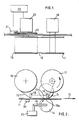
- a printing device has a thermal print head 10 containing a plurality of print elements 10a which can be selectively heated by the passage of electric current therethrough.
- thermal print heads are well known and it is believed to be un-necessary to describe the construction and operation thereof.
- Items 11 upon which printing is to be effected are fed past the print head 10 in the direction of arrow 12 by means of feed rollers 13, of which one is shown in Figures 2 and 3, and a co-operating impression roller 14.
- the feed rollers 13 are positioned on each side of the print head 10 and the impression roller 14 is of greater width than the print head and is urged resiliently toward the print head and the feed rollers.
- the feed rollers are driven by an electric motor (not shown).
- the print elements 10a in the present embodiment are disposed along a line extending transverse to the direction of feeding aligned substantially with a line along which the impression roller 14 presses toward the head.
- a thermal transfer ribbon 15 wound on a rotatable supply spool 16 passes from the spool 16 along the face of the print head 10 and thence to a rotatable take up spool 17.
- Ribbon guides 18 are provided at each end of the print head.
- the ribbon is a multi-strike ribbon in which only a portion of the ink is removed from areas corresponding to selected printing elements in a single printing operation.
- Multi-strike ribbons may contain the ink in a plurality of layers. Accordingly the ribbon can be used a number of times until the ink has been reduced to a level at which printing is expected to be unreliable.
- the feeding of the ribbon is controlled in such a manner as to result in repeated use of the ribbon during a single passage of the total length of the ribbon from the supply spool to the take up spool.
- the impression roller 14 is mounted in such a manner that it may be moved toward and away from the print head and feed rollers 13.
- it may be rotatably mounted on a pair of pivotable arms 24 and an electro-mechanical driver 25, mechanically connected to the arms 24 by suitable drive means, is provided to move the impression roller toward the print head to effect feeding of the item during printing on the item.
- the electromechanical driver 25 is actuated to move the impression roller 14 away from the print head to allow the item to continue moving in the direction of arrow 12 without drawing further ribbon from the spool 16. This also releases the ribbon from constraint and allows the ribbon to be partially rewound onto the supply spool 16 while also allowing the item 11 to be fed away from the print head in the direction of arrow 12.
- spring means may be provided to urge the impression roller toward the print head and the electro-mechanical driver is arranged to move the impression roller away from the print head against the action of the spring means
- An encoder disc 20 is secured to the shaft of the supply spool 16 and rotates with the supply spool.
- a sensor 21 responds to rotation of the encoder disc and generates electrical signals indicative of the amount of rotation of the supply spool 16.
- a rewind motor 22 is coupled to the shaft of the supply spool and is operable to withdraw the ribbon from the take up spool and to rewind it on the supply spool.
- a microprocessor 23 receives the signals from the sensor 21 and controls the operation of the rewind motor such as to rewind a proportion of the length of ribbon used during the immediately preceding printing operation. This may be accomplished by programming the microprocessor to count electrical pulses from the sensor as the encoder disc rotates during withdrawal of the ribbon from the supply spool and from this count to generate a value equal to a predetermined fraction of the count. During energisation of the rewind motor to rewind the ribbon onto the supply spool, the microprocessor is programmed to count pulses from the sensor and to compare this count with the fraction of count generated during unwinding of the ribbon. When these values are equal, energisation of the rewind motor is terminated.
- the positions of the supply and take up spools are interchanged.
- a short length of unused ribbon initially is wound onto the take up spool.
- the take up spool is driven by the rewind motor to wind a length of ribbon onto the take up spool which is greater than the length of ribbon withdrawn during printing.
- the length of ribbon fed in the interval between printing operations is a fraction, greater than unity, of the length of ribbon fed during each printing operation.
- the encoder disc is described as being mounted to rotate with the supply spool, if desired, the encoder disc may be mounted on the shaft of the take up spool so as to rotate with the take up spool. Alternatively, the encoder disc need not be coupled to one of the spools but may be coupled to an additional roller contacting the ribbon so as to be rotated by feeding of the ribbon.
- the electronic circuitry for the franking machine includes the microprocessor 23, a keyboard 26 for entering data and commands into the microprocessor and a display device 27 for displaying data and instruction information to a user of the machine.
- the circuitry also includes memories 28 and 29 for storing accounting data relating to the use of the franking machine in franking operations.
- the data stored in memory 28 is replicated in memory 29 in order to ensure integrity of the stored data.
- a sensor 30 is mounted, upstream of the drive and pressure rollers 13, 14 ( Figure 2), adjacent the feed path of the items 11 to detect the leading edge of an item 11 being fed to the print head 10.
- An electrical signal from the sensor 30 indicating detection of an item is input to the microprocessor 23 and in response the microprocessor actuates the electro-mechanical driver 25 to move the pressure roller toward the feed roller 13 and print head 10.
- the delays in the system are such that the leading end of the item is between the pressure and feed rollers as the former is moved toward the feed rollers.
- the microprocessor After a predetermined time period from sensing of the leading edge of the item, the microprocessor outputs print signals to the print elements 10a of the print head via print head driver circuits 31 to cause the print elements to effect transfer of ink from the ribbon to the surface of the item as the item together with the ribbon is fed past the print elements.
- Pulse signals from the sensor 21 resulting from rotation of the reel 16 are input to the microprocessor.
- these pulse signals are accumulated in a register 31 to provide a count representing the length of ribbon used.
- the microprocessor actuates the electro-mechanical driver to move the pressure roller 14 away from the feed roller 13.
- the microprocessor reads the count stored in the register 31, calculates a predetermined fraction of the count and then actuates the rewind motor 22 to rewind the ribbon until pulse signals from the sensor 21 during rewinding equal the value of the calculated fraction.
- the electrical pulse signals from the sensor 21 may be utilised to initiate an end of ribbon warning.
- a register 32 in or connected to the microprocessor 23 is set to store a value representing the amount of rotation of the spool needed to unwind the ribbon to near the end of the ribbon.
- the supply spool will be wound with a substantially uniform number of turns of ribbon.
- the value stored in the register 32 is a constant which may be set automatically by a signal generated upon installation of a ribbon. This signal may be generated by an input on the keyboard by the user of the machine upon installation of a new ribbon or if desired the signal could be generated by means responsive to the installation of a ribbon.
- Signals from the sensor 21 during unwinding of the ribbon from the supply spool cause the microprocessor to decrement the value in the register 32 whereas signals from the sensor during rewinding of the ribbon cause the value in the register to be incremented.
- a predetermined limit for example zero
- an end of ribbon warning is initiated and this may be displayed to the user on the display device 27.
- the print head comprises a single line of print elements extending transversely to the direction of feeding of the item 11 and printing is effected serially as the item is moved past the print heads.
- the print head may comprise print elements operable at the same time to print the entire impression.
- the printing device described hereinbefore is particularly suitable for use in a postal franking machine in which the print head is controlled by the franking meter of the machine to print franking impressions and other information on mail items such as envelopes or labels. While it is preferred to partially rewind the ribbon after printing has been completed on an item, if desired the rewinding may be performed less frequently for example after each second or third item of a series of items. Thus a printing operation may consist of printing on a group of one or more items in succession and the partial rewinding is effected in intervals between printing on groups of items.
Landscapes
- Physics & Mathematics (AREA)
- General Physics & Mathematics (AREA)
- Impression-Transfer Materials And Handling Thereof (AREA)
- Electronic Switches (AREA)
Applications Claiming Priority (2)
| Application Number | Priority Date | Filing Date | Title |
|---|---|---|---|
| GB8725619 | 1987-11-02 | ||
| GB878725619A GB8725619D0 (en) | 1987-11-02 | 1987-11-02 | Feed for thermal printing ribbon |
Publications (3)
| Publication Number | Publication Date |
|---|---|
| EP0315384A2 true EP0315384A2 (fr) | 1989-05-10 |
| EP0315384A3 EP0315384A3 (en) | 1989-11-02 |
| EP0315384B1 EP0315384B1 (fr) | 1994-07-20 |
Family
ID=10626285
Family Applications (1)
| Application Number | Title | Priority Date | Filing Date |
|---|---|---|---|
| EP88310170A Expired - Lifetime EP0315384B1 (fr) | 1987-11-02 | 1988-10-28 | Dispositif d'avance pour ruban d'impression thermique |
Country Status (4)
| Country | Link |
|---|---|
| US (1) | US4924240A (fr) |
| EP (1) | EP0315384B1 (fr) |
| DE (1) | DE3850741T2 (fr) |
| GB (1) | GB8725619D0 (fr) |
Cited By (4)
| Publication number | Priority date | Publication date | Assignee | Title |
|---|---|---|---|---|
| EP0354815A3 (en) * | 1988-08-12 | 1990-12-05 | Esselte Meto International Produktions Gmbh | Improvements relating to printing systems |
| GB2298821A (en) * | 1995-03-15 | 1996-09-18 | Prestek Ltd | A ribbon winding mechanism |
| EP0724232A3 (fr) * | 1995-01-30 | 1998-12-30 | Neopost Limited | Machine à timbrer et dispositif pour imprimer pour cette machine |
| US7731438B2 (en) * | 2006-08-29 | 2010-06-08 | Seiko Epson Corporation | Sheet bundle printer and sheet bundle printing system |
Families Citing this family (51)
| Publication number | Priority date | Publication date | Assignee | Title |
|---|---|---|---|---|
| GB2223455A (en) * | 1988-08-12 | 1990-04-11 | Scient Generics Ltd | Thermal printing |
| US5027702A (en) * | 1989-10-10 | 1991-07-02 | Unisys Corp. | Print drum with alignment marks |
| JPH03176175A (ja) * | 1989-12-06 | 1991-07-31 | Canon Inc | 熱転写記録装置 |
| GB9020596D0 (en) * | 1990-09-21 | 1990-10-31 | Alcatel Business Systems | Data transmission method and apparatus |
| US5293319A (en) * | 1990-12-24 | 1994-03-08 | Pitney Bowes Inc. | Postage meter system |
| GB2251217B (en) * | 1990-12-31 | 1994-10-05 | Alcatel Business Systems | Ink ribbon feed |
| JP2893220B2 (ja) * | 1991-04-24 | 1999-05-17 | 武藤工業株式会社 | ペ−パ−ム−ビングプロッタのロ−ル紙巻取制御方法 |
| US5309176A (en) * | 1992-08-25 | 1994-05-03 | Sci Systems, Inc. | Airline ticket printer with stepper motor for selectively engaging print head and platen |
| DE4228765C2 (de) * | 1992-08-28 | 1998-04-09 | Francotyp Postalia Gmbh | Andruckvorrichtung für eine Frankiermaschine mit einer elektrothermischen Druckvorrichtung |
| US5339280A (en) * | 1992-09-24 | 1994-08-16 | Pitney Bowes Inc. | Platen roller and pressure roller assemblies for thermal postage meter |
| US5318368A (en) * | 1992-09-24 | 1994-06-07 | Pitney Bowes Inc. | Thermal transfer ribbon having ribbon follower |
| US5555012A (en) * | 1994-06-01 | 1996-09-10 | Eastman Kodak Company | Method and apparatus for improved use of thermal donor media |
| DE19509683C2 (de) * | 1995-03-07 | 2000-06-21 | Francotyp Postalia Gmbh | Thermotransferdruckverfahren und Anordnung zur Durchführung des Verfahrens mit Multi-Use-Farbbandkassette |
| DE19549376A1 (de) * | 1995-03-07 | 1996-09-26 | Francotyp Postalia Gmbh | Anordnung zur Ermittlung einer Farbbandrestmenge für Thermotransferdruckverfahren |
| JPH11348395A (ja) * | 1998-06-04 | 1999-12-21 | Fuji Photo Film Co Ltd | プリンタのインクリボンゴミ付着防止方法およびそのプリンタ |
| US6256865B1 (en) | 1999-06-07 | 2001-07-10 | General Electric Company | Continuous winding process and apparatus for electrical transformers |
| JP2001010138A (ja) * | 1999-06-28 | 2001-01-16 | Seiko Precision Inc | プリンタ |
| AU2001286048A1 (en) * | 2000-09-11 | 2002-03-26 | Zipher Limited | Tape drive and printing apparatus |
| GB2391514B (en) * | 2002-08-06 | 2006-03-22 | Markem Tech Ltd | Printing apparatus and methods |
| US20070172130A1 (en) * | 2006-01-25 | 2007-07-26 | Konstantin Zuev | Structural description of a document, a method of describing the structure of graphical objects and methods of object recognition. |
| JP2007510557A (ja) * | 2003-09-12 | 2007-04-26 | ファーゴ・エレクトロニクス・インコーポレーテッド | 反転画像idカードプリンタ |
| GB2448305B (en) * | 2007-03-07 | 2009-03-11 | Zipher Ltd | Tape drive |
| GB2448304B (en) * | 2007-03-07 | 2009-03-11 | Zipher Ltd | Tape drive |
| GB2448301B (en) * | 2007-03-07 | 2009-03-11 | Zipher Ltd | Tape drive |
| GB2448303B (en) * | 2007-03-07 | 2009-03-11 | Zipher Ltd | Tape drive |
| GB2448302B (en) | 2007-03-07 | 2009-04-08 | Zipher Ltd | Tape drive |
| EP2134549B1 (fr) * | 2007-03-31 | 2014-11-19 | Videojet Technologies, Inc. | Dérouleur de bande |
| CN102056745A (zh) * | 2008-06-13 | 2011-05-11 | 勃来迪环球股份有限公司 | 用于监测和确定打印机中使用的供应卷轴上色带量的系统和方法 |
| EP2477819B1 (fr) | 2009-09-18 | 2019-08-14 | Assa Abloy AB | Alimentation d'un substrat d'élément d'identification dans un dispositif de traitement d'élément d'identification |
| EP2716026A4 (fr) | 2011-05-23 | 2014-12-24 | Datamax O Neil Corp | Dispositif de détection pour détecter et déterminer la largeur d'un support le long d'un chemin d'alimentation |
| EP2718676B1 (fr) * | 2011-06-06 | 2019-04-17 | Datamax-O'Neil Corporation | Appareil et procédé de sécurisation d'un ruban d'impression |
| EP2723574B1 (fr) | 2011-06-23 | 2019-08-07 | Datamax-O'Neil Corporation | Station d'impression |
| WO2012177978A1 (fr) | 2011-06-24 | 2012-12-27 | Source Technologies, Llc | Appareil et procédé de détermination et d'ajustement de pression de tête d'impression |
| EP2723575A4 (fr) | 2011-06-24 | 2015-05-06 | Datamax O Neil Corp | Ensemble d'entraînement de ruban |
| EP2731797A4 (fr) | 2011-07-14 | 2015-04-08 | Datamax O Neil Corp | Adaptation automatique de paramètres d'impression par identification de support |
| EP2739480A4 (fr) | 2011-08-05 | 2016-02-24 | Datamax O Neil Corp | Système de station d'impression |
| EP2739479B1 (fr) | 2011-08-05 | 2017-06-14 | Datamax-O'Neil Corporation | Système d'impression |
| GB2493541A (en) | 2011-08-10 | 2013-02-13 | Markem Imaje Ltd | Motor control system using position or torque as dominant control parameter |
| WO2013025750A1 (fr) | 2011-08-15 | 2013-02-21 | Videojet Technologies Inc. | Imprimante à transfert thermique |
| CA2852928A1 (fr) | 2011-10-20 | 2013-04-25 | Source Technologies, Llc | Capteur de debut de page |
| CA2856420A1 (fr) | 2011-11-22 | 2013-05-30 | Datamax-O'neil Corporation | Element de suspension/guide d'objets synchronise |
| US8791585B2 (en) * | 2011-12-14 | 2014-07-29 | Grant Howard Calverley | Power systems |
| WO2013096439A1 (fr) | 2011-12-22 | 2013-06-27 | Datamax-O'neil Corporation | Appareil et procédé de détection de support |
| GB2507771B (en) | 2012-11-09 | 2020-03-04 | Dover Europe Sarl | Tape drive and method of operation of a tape drive |
| US9061527B2 (en) | 2012-12-07 | 2015-06-23 | Datamax-O'neil Corporation | Thermal printer with single latch, adjustable media storage and centering assemblies and print assembly |
| GB2536772B (en) | 2013-02-12 | 2017-07-05 | Dover Europe Sàrl | Tape drive and method of operation |
| GB2510834B (en) | 2013-02-13 | 2017-01-18 | Dover Europe Sarl | Printing apparatus and method of operating a printing apparatus |
| GB2510832B (en) * | 2013-02-13 | 2020-02-26 | Dover Europe Sarl | Tape drive and method of operation of a tape drive |
| US9676216B2 (en) | 2014-03-27 | 2017-06-13 | Datamax-O'neil Corporation | Systems and methods for automatic printer configuration |
| JP6298713B2 (ja) * | 2014-05-23 | 2018-03-20 | キヤノンファインテックニスカ株式会社 | 印刷装置 |
| CN104626769B (zh) * | 2015-02-13 | 2017-04-26 | 深圳市速普特智能科技有限公司 | 打印色带驱动装置 |
Family Cites Families (5)
| Publication number | Priority date | Publication date | Assignee | Title |
|---|---|---|---|---|
| US3954167A (en) * | 1974-10-17 | 1976-05-04 | Extel Corporation | High speed printer |
| DE2717721A1 (de) * | 1977-04-21 | 1978-10-26 | Postalia Gmbh | Anlage zur frankierung von postsendungen |
| GB2144081B (en) * | 1983-07-23 | 1987-10-28 | Pa Consulting Services | Postal franking machines |
| JPS61160267A (ja) * | 1985-01-08 | 1986-07-19 | Toshiba Corp | 画像形成装置 |
| US4760405A (en) * | 1985-10-22 | 1988-07-26 | Canon Kabushiki Kaisha | Method and apparatus for recording an image |
-
1987
- 1987-11-02 GB GB878725619A patent/GB8725619D0/en active Pending
-
1988
- 1988-10-28 DE DE3850741T patent/DE3850741T2/de not_active Expired - Fee Related
- 1988-10-28 EP EP88310170A patent/EP0315384B1/fr not_active Expired - Lifetime
- 1988-10-31 US US07/264,832 patent/US4924240A/en not_active Expired - Lifetime
Cited By (5)
| Publication number | Priority date | Publication date | Assignee | Title |
|---|---|---|---|---|
| EP0354815A3 (en) * | 1988-08-12 | 1990-12-05 | Esselte Meto International Produktions Gmbh | Improvements relating to printing systems |
| EP0724232A3 (fr) * | 1995-01-30 | 1998-12-30 | Neopost Limited | Machine à timbrer et dispositif pour imprimer pour cette machine |
| US6065883A (en) * | 1995-01-30 | 2000-05-23 | Neopost Limited | Franking apparatus and printing means thereof |
| GB2298821A (en) * | 1995-03-15 | 1996-09-18 | Prestek Ltd | A ribbon winding mechanism |
| US7731438B2 (en) * | 2006-08-29 | 2010-06-08 | Seiko Epson Corporation | Sheet bundle printer and sheet bundle printing system |
Also Published As
| Publication number | Publication date |
|---|---|
| EP0315384B1 (fr) | 1994-07-20 |
| US4924240A (en) | 1990-05-08 |
| DE3850741T2 (de) | 1995-03-16 |
| GB8725619D0 (en) | 1987-12-09 |
| DE3850741D1 (de) | 1994-08-25 |
| EP0315384A3 (en) | 1989-11-02 |
Similar Documents
| Publication | Publication Date | Title |
|---|---|---|
| US4924240A (en) | Feed for thermal printing ribbon | |
| US5294203A (en) | Ink ribbon feed | |
| EP0253618B1 (fr) | Appareil et procédé d'impression thermique | |
| EP0132471B1 (fr) | Machine à affranchir | |
| EP0712098B2 (fr) | Dispositif et procédé pour détecter la position d'une enveloppe dans une machine à affranchir | |
| US5683190A (en) | Franking apparatus and mail transport thereof | |
| EP0604160A2 (fr) | Appareil d'impression thermique capable d'imprimer à vitesse variable | |
| EP0493944B1 (fr) | Alimentation avec un ruban encreur | |
| EP0556071B1 (fr) | Imprimante de tickets | |
| US6065883A (en) | Franking apparatus and printing means thereof | |
| US6019526A (en) | Thermal printing apparatus | |
| US5414449A (en) | Thermal transfer printing apparatus | |
| US4982202A (en) | Thermal printing cartridge | |
| EP0165601B1 (fr) | Imprimante thermique et machine à timbrer ayant une imprimante thermique | |
| US4899172A (en) | Method and apparatus for perforating indicia on used thermal transfer ribbon within a cassette | |
| EP0550227B1 (fr) | Commande de l'alimentation d'un ruban encreur à frappe multiple | |
| EP0604142B1 (fr) | Cartouche pour ruban encreur thermique capable de contenir un ruban de transfert à base polymère ou cireuse à utiliser en combinaison avec un appareil d'impression thermique | |
| US4926193A (en) | Thermal transfer ribbon cartridge including ribbon perforating means | |
| EP0589715B1 (fr) | Commande de tension de la bande thermique d'une cassette pour une machine à affranchir ayant une imprimante thermique | |
| EP1125753B1 (fr) | Procédé et dispositif pour imprimer sur cartes à puce et analogues | |
| GB2202797A (en) | Thermal printing apparatus | |
| GB2297293A (en) | Controlling thermal printing parameters in postage meters in response to coded ink-ribbon cassettes | |
| JP3085883B2 (ja) | 券処理装置 | |
| GB2058674A (en) | Ticket printing machine | |
| JPH05258136A (ja) | 発券装置 |
Legal Events
| Date | Code | Title | Description |
|---|---|---|---|
| PUAI | Public reference made under article 153(3) epc to a published international application that has entered the european phase |
Free format text: ORIGINAL CODE: 0009012 |
|
| AK | Designated contracting states |
Kind code of ref document: A2 Designated state(s): DE FR GB |
|
| PUAL | Search report despatched |
Free format text: ORIGINAL CODE: 0009013 |
|
| AK | Designated contracting states |
Kind code of ref document: A3 Designated state(s): DE FR GB |
|
| 17P | Request for examination filed |
Effective date: 19900501 |
|
| 17Q | First examination report despatched |
Effective date: 19910821 |
|
| RAP1 | Party data changed (applicant data changed or rights of an application transferred) |
Owner name: NEOPOST LIMITED |
|
| GRAA | (expected) grant |
Free format text: ORIGINAL CODE: 0009210 |
|
| AK | Designated contracting states |
Kind code of ref document: B1 Designated state(s): DE FR GB |
|
| REF | Corresponds to: |
Ref document number: 3850741 Country of ref document: DE Date of ref document: 19940825 |
|
| ET | Fr: translation filed | ||
| PLBE | No opposition filed within time limit |
Free format text: ORIGINAL CODE: 0009261 |
|
| STAA | Information on the status of an ep patent application or granted ep patent |
Free format text: STATUS: NO OPPOSITION FILED WITHIN TIME LIMIT |
|
| 26N | No opposition filed | ||
| REG | Reference to a national code |
Ref country code: GB Ref legal event code: IF02 |
|
| PGFP | Annual fee paid to national office [announced via postgrant information from national office to epo] |
Ref country code: GB Payment date: 20051007 Year of fee payment: 18 |
|
| PGFP | Annual fee paid to national office [announced via postgrant information from national office to epo] |
Ref country code: DE Payment date: 20051014 Year of fee payment: 18 |
|
| PGFP | Annual fee paid to national office [announced via postgrant information from national office to epo] |
Ref country code: FR Payment date: 20051027 Year of fee payment: 18 |
|
| PG25 | Lapsed in a contracting state [announced via postgrant information from national office to epo] |
Ref country code: DE Free format text: LAPSE BECAUSE OF NON-PAYMENT OF DUE FEES Effective date: 20070501 |
|
| GBPC | Gb: european patent ceased through non-payment of renewal fee |
Effective date: 20061028 |
|
| REG | Reference to a national code |
Ref country code: FR Ref legal event code: ST Effective date: 20070629 |
|
| PG25 | Lapsed in a contracting state [announced via postgrant information from national office to epo] |
Ref country code: GB Free format text: LAPSE BECAUSE OF NON-PAYMENT OF DUE FEES Effective date: 20061028 |
|
| PG25 | Lapsed in a contracting state [announced via postgrant information from national office to epo] |
Ref country code: FR Free format text: LAPSE BECAUSE OF NON-PAYMENT OF DUE FEES Effective date: 20061031 |