EP0315411B1 - Ortungssystem - Google Patents
Ortungssystem Download PDFInfo
- Publication number
- EP0315411B1 EP0315411B1 EP88310268A EP88310268A EP0315411B1 EP 0315411 B1 EP0315411 B1 EP 0315411B1 EP 88310268 A EP88310268 A EP 88310268A EP 88310268 A EP88310268 A EP 88310268A EP 0315411 B1 EP0315411 B1 EP 0315411B1
- Authority
- EP
- European Patent Office
- Prior art keywords
- target
- signal
- receiving station
- oscillator
- base receiving
- Prior art date
- Legal status (The legal status is an assumption and is not a legal conclusion. Google has not performed a legal analysis and makes no representation as to the accuracy of the status listed.)
- Expired - Lifetime
Links
- 238000000034 method Methods 0.000 claims description 16
- 230000001133 acceleration Effects 0.000 claims description 7
- 238000012545 processing Methods 0.000 claims description 6
- 238000005259 measurement Methods 0.000 description 17
- 230000008859 change Effects 0.000 description 3
- 238000004891 communication Methods 0.000 description 3
- 238000012937 correction Methods 0.000 description 3
- 238000010586 diagram Methods 0.000 description 3
- 230000036039 immunity Effects 0.000 description 3
- 230000008901 benefit Effects 0.000 description 2
- 230000003247 decreasing effect Effects 0.000 description 2
- 238000011161 development Methods 0.000 description 2
- 230000000694 effects Effects 0.000 description 2
- 230000008569 process Effects 0.000 description 2
- 238000004458 analytical method Methods 0.000 description 1
- 238000006243 chemical reaction Methods 0.000 description 1
- 230000001427 coherent effect Effects 0.000 description 1
- 238000010276 construction Methods 0.000 description 1
- 230000001934 delay Effects 0.000 description 1
- 238000011156 evaluation Methods 0.000 description 1
- 230000007246 mechanism Effects 0.000 description 1
- 238000012986 modification Methods 0.000 description 1
- 230000004048 modification Effects 0.000 description 1
- 238000004445 quantitative analysis Methods 0.000 description 1
- 239000010453 quartz Substances 0.000 description 1
- VYPSYNLAJGMNEJ-UHFFFAOYSA-N silicon dioxide Inorganic materials O=[Si]=O VYPSYNLAJGMNEJ-UHFFFAOYSA-N 0.000 description 1
- 230000001360 synchronised effect Effects 0.000 description 1
- 238000012360 testing method Methods 0.000 description 1
- 238000013519 translation Methods 0.000 description 1
Images

Classifications
-
- G—PHYSICS
- G01—MEASURING; TESTING
- G01S—RADIO DIRECTION-FINDING; RADIO NAVIGATION; DETERMINING DISTANCE OR VELOCITY BY USE OF RADIO WAVES; LOCATING OR PRESENCE-DETECTING BY USE OF THE REFLECTION OR RERADIATION OF RADIO WAVES; ANALOGOUS ARRANGEMENTS USING OTHER WAVES
- G01S5/00—Position-fixing by co-ordinating two or more direction or position line determinations; Position-fixing by co-ordinating two or more distance determinations
- G01S5/02—Position-fixing by co-ordinating two or more direction or position line determinations; Position-fixing by co-ordinating two or more distance determinations using radio waves
- G01S5/06—Position of source determined by co-ordinating a plurality of position lines defined by path-difference measurements
Definitions
- This invention relates to a target tracking system for a vehicle and has been devised particularly, though not necessarily, solely for tracking the position of a vehicle such as a racing vehicle.
- Target tracking systems are already known, for example, DD-A-28325 describes a remote vehicle tracking system using pulse-travel-time measurement where there is provided a vehicle with an on board transmitter, three receivers located at fixed ground stations and an evaluation centre. This system must recalculate the entire position parameters of the target to locate the target at any given time. Clearly, it would be advantageous to locate the target in terms of its shift from a previous position rather than recalculating the entire position parameters each time.
- a further target tracking system is disclosed in EP-A-0,006,594.
- This system uses phase difference measurement as a means of tracking a target.
- Each of the spaced receivers compares the signal transmitted by the target vehicle with a similar reference signal supplied by a quartz oscillator. The phase difference resulting from this comparison is transmitted to a central station as a digital message telegram.
- the system also uses a reference transmitter at a distance from each receiver which transmits a signal which is compared with the reference signal used by each receiver to obtain a correction value for the phase difference obtained when the signal transmitted by the vehicle is compared with the reference signal.
- this system requires a large number of components since each receiver is provided with both a comparing means and a reference transmitter.
- the present invention provides a target tracking system comprising: an oscillator on a target (T); a transmitter on said target and operatively connected to said oscillator whereby a signal representative of a signal generated by said oscillator is transmitted by said transmitter at a selected frequency; a base receiving station (A); at least three spaced apart translators (B,C,D) whereby the transmitted signal is received and transmitted to said base receiving station (A); characterised by said transmitted signal being continuous; said base receiving station also receiving said transmitted signal directly from said transmitter and said base receiving station including a reference oscillator; processing means at said base receiving station to enable synchronicity to be maintained between said reference oscillator and the oscillator on said target; and comparing means connected to said processing means to compare phase changes in the signal received directly from said transmitter and signals retransmitted by said means for translating with a signal generated by said reference oscillator, thereby tracking position parameters of the target relative to the translators and the base receiving station.
- the present invention also provides: a method of tracking a target (T) comprising: generating an oscillating signal at said target (T); transmitting a signal representative of said oscillating signal, at a selected frequency from said target; receiving said transmitted signal at at least three spaced apart translators (B,C,D); retransmitting the received signal to a base receiving station (A) from each of said spaced apart translators; characterised by said transmitted signal being continuous; receiving said transmitted signal directly from the target at said base receiving station; processing the signals received by the base receiving station so as to maintain synchronicity between a reference oscillator at said base receiving station and the oscillator on said target; and comparing phase changes in the signal received directly from said target and signals retransmitted by said translators with a signal generated by said reference oscillator, thereby tracking position parameters of said target relative to said translators and said base receiving station.
- the overall purpose of the tracking system is to obtain the position, velocity and acceleration of a target (such as a vehicle) moving within a defined area.
- a target such as a vehicle
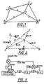
- a system that will provide these measurements is shown in outline on figure 1.
- This is a VHF phase comparison system that takes advantage of the fact that, with four observing stations, the phase ambiguities normally associated with such systems can be resolved without recourse to any new setting up procedure.
- the first is the initial setting up or "calibrating" procedure and the second is that of recovering from a situation, during operation, where one or more of the signals from the target to the receiving stations are temporarily lost.
- the initial setting up is most easily accomplished by using a known location for the target, while the complexity of resolving the second problem depends on how many of the signals are temporarily lost.
- the system can cope with the temporary loss of all signals although there will, of course, be a gap in the data should this occur.
- the target is provided with a stable oscillator that generates a signal at a selected frequency, preferably a continous signal at say 36.25 MHz, a recognized telemetry band.
- the wavelength is thus about 8.3m so that any measurement of the received phase of this signal with respect to some other coherent signal at the same frequency such as an identical oscillator at a base receiving station, is ambiguous by some unknown multiple of 8.3m.
- phase comparisons are carried out at the base station A where the signal from the target is received by four different routes TA, TBA, TCA and TDA. Changes in these distances as the target is moved are then observable since the way in which the phase of the received wave changes with respect to the reference oscillator at A can be continually monitored.
- the first is that the signal from the target must be received continuously over all channels i.e. a drop-out for some reason over a particular channel means that the ambiguity of some integral number of wavelengths is reintroduced.
- the resolution of the ambiguity can be accomplished quite rapidly once the signal re-appears.
- the second problem is that, although it has been postulated that synchronous oscillators are used in the target and at the base receiving station to enable the phase comparisons to be carried out, there is always the possibility that some drift of the oscillators relative to each other will occur.
- the standard oscillators proposed for this purpose can be relied on to about 1 part in 109 in this application where the target is subjected to considerable accelerations. This is equivalent to a range error that could be increasing or decreasing by about 2m every 6 seconds. But all ranges ie a, b, c and d, will increase or decrease together.
- the geometrical relationship mentioned above also allows this drift, if any, to be monitored continuously so that the appropriate corrections can be made. It is thus possible that much less sophisticated oscillators could be used.
- the geometrical expression used for drift correction is also discussed under the heading of Geometic Considerations.
- the system as described above provides position measurements and, since all distances are measured continuously, outputs are provided essentially continuously.
- the rate at which outputs giving new information on the position are available depends on the bandwidth of the system. This is a quantity that should be small enough to ensure immunity against interference from ignition noise, for example, while still being large enough to accommodate any oscillator drift and the doppler shift arising from the motion of the target. With the stable oscillators that are proposed, the frequency drift will be much less than 1 Hz so that this presents no problem.
- the doppler shift that is observed when the target is moving directly towards or away from one of the observing stations at 100m/sec (360 km/hr or 220 mph) is about ⁇ 12 Hz.
- an overall bandwidth of ⁇ 100Hz would enable measurements to be made at the rate of 50 per second if required and would give excellent noise immunity with quite small power radiated from the target. This is discussed in more detail under the heading Antennae and Power.
- Velocity measurements can be obtained from the difference between successive position measurements and can also be obtained from a direct measure of the doppler shift of the received signals. Since this gives an independent check of the position measurements it is proposed that both measurements be made.
- the measurements of acceleration can be made from the difference between successive velocity measurements. From the equipment there will also be control signals available that are proportional to the acceleration components in the directions of a.b.c. and d and this will provide a check on the velocity measurements if desired.
- the second, fourth and fifth have numerators that are not primes so that at least the divisions or multiplications that are required at the higher frequency are simplified. These then give frequencies of 160.263, 160.174 and 160.149 for the communication links. Although these are not standard for Band C, the facts that only low power is required and that the antennae are directional so that the signals are not widely disseminated should make them acceptable to any licensing authority.
- the target transmitter frequency of 36.250 MHz has a quarter-wave-length of 2.07m. This can be used as the length of the receiving antennae at A, B, C and D but is rather large for the target vehicle. However, the required physical length can be reduced drastically by using a double-spiral-wound or zig-zag antenna.
- the target vehicle contains a stable oscillator such as a 10MHz oscillator from which the equally stable transmitted frequency is derived.
- a stable oscillator such as a 10MHz oscillator from which the equally stable transmitted frequency is derived.
- a straightforward way of accomplishing this is suggested in figure 3.
- An identical unit is required for the reference standard at station A.
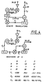
- the translators must convert this frequency of 36.25 MHz to one of these three chosen communication frequencies of 160.263, 160.174 and 160.149 MHz. Suggested methods of accomplishing this are shown at the top of figure 4.
- phase-locked-loops are included in each unit in order to provide the narrow bandwidths needed to ensure noise immunity and also to provide clean signals for dividing by the rather unusual integers required.
- the frequencies of the local oscillators have been chosen so that they are all in the same general range and thus are more or less compatible i.e. development time should be minimized.
- the lowest frequency used in the circuit is .541 MHz (for receiver D) so that the phase jitters arising from excessive multiplication ratios should be satisfactorily small.
- Identical components are used in the receivers at the base station A, again to reduce development time.
- phase multiplication can be introduced since all the signals are now available, for the first time in the system, at the same frequency. This is accomplished by mixing all channels down to 10 kHz using the same mixing signal of 36.240 MHz and then multiplying by 10. The phase comparisons are then carried out at 100 KHz. This is achieved by the circuits in figure 5.
- the top circuit is a modification of figure 3 since we now require a different frequency.
- the two outputs are related as shown in the bottom of figure 5.
- Simple logic circuits determine whether the distance being measured is increasing or decreasing and then counts of zero crossings give the distance to within ⁇ 0.21m. It is straightforward to include A/D converters to interpolate within this accuracy.
- a recalibration or initial calibration can be accomplished by moving the target to a succession of different positions, all of which can be unknown.
- the positions be labelled as 1, 2, . . . . so that the catual distances are (a1, b1, c1, d1,), (a2, b2, c2, d2), . . .
- the measured positions will then be (A1, B1, C1, D1), (A2, B2, C2, D2), . . . where there are unknown but constant ambiguities in each measurement.
- A1 a1+ ⁇
- B1 b1+ ⁇
- C1 c1+ ⁇
- D1 d1+ ⁇
- A2 a2+ ⁇
- B2 b2+ ⁇
- C2 c2+ ⁇
- D2 d2+ ⁇
- the information from any group of 4 can be used to include another station to compensate for the loss of a station and the ambiguity problem for the new station is resolved very quickly i.e. the full analysis needed to obtain all the unknown constants together is not required.
- the invention can be used to track a target for example a vehicle such as a racing motor vehicle.
- the system and apparatus can therefore be used during testing of a vehicle so that a quantitative analysis can be obtained of the effect of varying different components such as tyres, aerofoil dimensions, weight distribution, and the like.
- a vehicle tracking system which has the advantage that a highly accurate quantitative vehicle tracking system is provided which will allow detailed comparison to be made of quantities such as velocity and acceleration of a vehicle where changes have been made to the construction or setting up of the vehicle. This is clearly advantageous.
Landscapes
- Physics & Mathematics (AREA)
- Engineering & Computer Science (AREA)
- General Physics & Mathematics (AREA)
- Radar, Positioning & Navigation (AREA)
- Remote Sensing (AREA)
- Position Fixing By Use Of Radio Waves (AREA)
- Radar Systems Or Details Thereof (AREA)
Claims (4)
- Zielverfolgungssystem mit:
einem Oszillator auf einem Ziel (T);
einem Sender auf dem Ziel, der mit dem Oszillator betrieblich verbunden ist, so daß ein Signal, das ein von dem Oszillator erzeugtes Signal wiedergibt, von dem Sender bei einer gewählten Frequenz ausgesendet wird;
einer Basisempfangsstation (A);
mindestens drei in Abständen voneinander angeordneten Umsetzern (B,C,D), durch die das ausgesendete Signal empfangen und zur Basisstation (A) gesendet wird;
dadurch gekennzeichnet, daß das gesendete Signal kontinuierlich ist;
daß die Basisempfangsstation auch das vom Sender ausgesandte Signal direkt empfängt und die Basisempfangsstation einen Referenzoszillator enthält;
Verarbeitungsmittel an der Basisempfangsstation zum Aufrechterhalten der Synchronität zwischen dem Referenzoszillator und dem Oszillator auf dem Ziel;
und mit den Verarbeitungsmitteln verbundene Vergleichsmittel zum Vergleich von Phasenänderungen in dem direkt vom Empfänger empfangenen Signal und den von den Umsetzern wieder ausgesendeten Signalen mit einem von dem Referenzoszillator erzeugten Signal, wodurch Positionsparameter des Ziels relativ zu den Umsetzern und der Basisempfangsstation verfolgt werden. - Zielverfolgungssystem nach Anspruch 1, bei dem das Ziel (T) ein bewegliches Ziel in einem definierten Bereich ist und die Positionsparameter des Ziels die Position, Geschwindigkeit und Beschleunigung des Ziels in dem definierten Bereich beinhalten.
- Verfahren zum Verfolgen eines Ziels (T), bei dem ein Oszillationssignal an dem Ziel (T) erzeugt wird;
ein für das Oszillationssignal repräsentatives Signal bei einer gewählten Frequenz von dem Ziel ausgesendet wird;
das ausgesendete Signal an mindestens drei in Abständen angeordneten Umsetzern (B,C,D) empfangen wird;
das empfangene Signal von jedem der in Abständen angeordneten Umsetzer zu einer Basisempfangsstation (A) wieder ausgesendet wird;
dadurch gekennzeichnet, daß das gesendete Signal kontinuierlich ist;
daß das gesendete Signal an der Basisempfangsstation direkt vom Ziel empfangen wird;
daß die von der Basisstation empfangenen Signale derart verarbeitet werden, daß Synchronität zwischen einem Bezugsoszillator an der Basisempfangsstation und dem Oszillator am Ziel aufrechterhalten wird; und
daß Phasenänderungen in dem direkt vom Ziel empfangenen Signal und den von den Umsetzern wieder ausgesendeten Signalen mit einem von dem Bezugssignal erzeugten Signal verglichen werden und dadurch Positionsparameter des Ziels relativ zu den Umsetzern und der Basisempfangsstation verfolgt werden. - Verfahren nach Anspruch 3, bei dem die Positionsparameter die Position, Geschwindigkeit und Beschleunigung des Ziels (T) in dem definierten Bereich beinhalten.
Applications Claiming Priority (2)
| Application Number | Priority Date | Filing Date | Title |
|---|---|---|---|
| NZ222404 | 1987-02-02 | ||
| NZ222404A NZ222404A (en) | 1987-11-02 | 1987-11-02 | Vehicle tracking by comparison of transmitted phase at multiple receivers |
Publications (2)
| Publication Number | Publication Date |
|---|---|
| EP0315411A1 EP0315411A1 (de) | 1989-05-10 |
| EP0315411B1 true EP0315411B1 (de) | 1994-06-01 |
Family
ID=19922263
Family Applications (1)
| Application Number | Title | Priority Date | Filing Date |
|---|---|---|---|
| EP88310268A Expired - Lifetime EP0315411B1 (de) | 1987-11-02 | 1988-11-01 | Ortungssystem |
Country Status (6)
| Country | Link |
|---|---|
| US (1) | US5023809A (de) |
| EP (1) | EP0315411B1 (de) |
| JP (1) | JPH01259280A (de) |
| AT (1) | ATE106575T1 (de) |
| DE (1) | DE3889852D1 (de) |
| NZ (1) | NZ222404A (de) |
Families Citing this family (14)
| Publication number | Priority date | Publication date | Assignee | Title |
|---|---|---|---|---|
| US5500904A (en) * | 1992-04-22 | 1996-03-19 | Texas Instruments Incorporated | System and method for indicating a change between images |
| US5327144A (en) * | 1993-05-07 | 1994-07-05 | Associated Rt, Inc. | Cellular telephone location system |
| NL9301186A (nl) * | 1993-07-06 | 1995-02-01 | Franciscus Johannes Maria Olij | Mobiel wedstrijd-volgsysteem. |
| US5890068A (en) * | 1996-10-03 | 1999-03-30 | Cell-Loc Inc. | Wireless location system |
| US6330452B1 (en) | 1998-08-06 | 2001-12-11 | Cell-Loc Inc. | Network-based wireless location system to position AMPs (FDMA) cellular telephones, part I |
| US6208297B1 (en) | 1998-10-09 | 2001-03-27 | Cell-Loc Inc. | Methods and apparatus to position a mobile receiver using downlink signals, part I |
| US6204812B1 (en) | 1998-10-09 | 2001-03-20 | Cell-Loc Inc. | Methods and apparatus to position a mobile receiver using downlink signals, part II |
| US6266014B1 (en) | 1998-10-09 | 2001-07-24 | Cell-Loc Inc. | Methods and apparatus to position a mobile receiver using downlink signals part IV |
| US6574478B1 (en) * | 2000-08-11 | 2003-06-03 | Alcatel Usa Sourcing, L.P. | System and method for locating mobile devices |
| EP1360833A1 (de) | 2000-08-31 | 2003-11-12 | Rytec Corporation | Sensor und abbildungssystem |
| WO2004023787A2 (en) | 2002-09-06 | 2004-03-18 | Rytec Corporation | Signal intensity range transformation apparatus and method |
| US8436730B2 (en) | 2007-10-04 | 2013-05-07 | Sc Holdings, Llc | Method and system for tracking and/or disabling a vehicle |
| US20100006908A1 (en) * | 2008-07-09 | 2010-01-14 | Brady Frederick T | Backside illuminated image sensor with shallow backside trench for photodiode isolation |
| CN109856594B (zh) * | 2019-01-31 | 2020-10-13 | 北京电子工程总体研究所 | 一种时差测量体制无源定位的多路可控时延信号产生装置 |
Family Cites Families (9)
| Publication number | Priority date | Publication date | Assignee | Title |
|---|---|---|---|---|
| FR1230585A (fr) * | 1959-04-01 | 1960-09-16 | Dispositif radioélectrique pour la localisation d'un mobile | |
| DE2460645A1 (de) * | 1971-07-28 | 1976-06-24 | Siemens Ag | Verfahren zur standortbestimmung von fahrzeugen und einrichtung zur durchfuehrung des verfahrens |
| DE2829558A1 (de) * | 1978-07-05 | 1980-01-24 | Siemens Ag | Phasenvergleichs-hyperbelverfahren zur ortung flaechengebundener fahrzeuge und einrichtung zur durchfuehrung des verfahrens |
| US4270143A (en) * | 1978-12-20 | 1981-05-26 | General Electric Company | Cross-correlation video tracker and method |
| US4320287A (en) * | 1980-01-25 | 1982-03-16 | Lockheed Electronics Co., Inc. | Target vehicle tracking apparatus |
| JPS5994045A (ja) * | 1982-11-22 | 1984-05-30 | Toshiba Corp | 画像入力装置 |
| US4550435A (en) * | 1983-06-07 | 1985-10-29 | Rca Corporation | Multilevel thresholding for target tracking apparatus |
| US4739401A (en) * | 1985-01-25 | 1988-04-19 | Hughes Aircraft Company | Target acquisition system and method |
| US4823137A (en) * | 1987-04-13 | 1989-04-18 | Mallick Brian C | Multiple-fixed-frequencies navigation system |
-
1987
- 1987-11-02 NZ NZ222404A patent/NZ222404A/en unknown
-
1988
- 1988-11-01 EP EP88310268A patent/EP0315411B1/de not_active Expired - Lifetime
- 1988-11-01 AT AT88310268T patent/ATE106575T1/de active
- 1988-11-01 DE DE3889852T patent/DE3889852D1/de not_active Expired - Lifetime
- 1988-11-02 JP JP63276340A patent/JPH01259280A/ja active Pending
-
1990
- 1990-06-19 US US07/541,089 patent/US5023809A/en not_active Expired - Fee Related
Non-Patent Citations (1)
| Title |
|---|
| NACHRICHTEN ELEKTRONIK, vol. 35, no. 2, 1985, pages 65-67, Berlin, DDR; C.WOBUS et al.: "Standortbestimmung von mobilen Funkstationen" * |
Also Published As
| Publication number | Publication date |
|---|---|
| EP0315411A1 (de) | 1989-05-10 |
| JPH01259280A (ja) | 1989-10-16 |
| NZ222404A (en) | 1991-06-25 |
| ATE106575T1 (de) | 1994-06-15 |
| DE3889852D1 (de) | 1994-07-07 |
| US5023809A (en) | 1991-06-11 |
Similar Documents
| Publication | Publication Date | Title |
|---|---|---|
| US4613864A (en) | Position-fixing system | |
| US4719469A (en) | Direction-determining system | |
| US6111536A (en) | System and method for distance measurement by inphase and quadrature signals in a radio system | |
| US5365447A (en) | GPS and satelite navigation system | |
| EP2624006B1 (de) | Frequenzkohärenz innerhalb eines Standortnetzwerks | |
| EP0315411A1 (de) | Ortungssystem | |
| US5477458A (en) | Network for carrier phase differential GPS corrections | |
| US3742498A (en) | Synchronization and position location system | |
| AU629728B2 (en) | Method and system for determining data using signals from gps satellites | |
| US5063387A (en) | Doppler frequency compensation circuit | |
| US4847862A (en) | Global positioning system course acquisition code receiver | |
| US3430234A (en) | Navigation systems using earth satellites | |
| US20060064244A1 (en) | Differential GPS corrections using virtual stations | |
| US3900873A (en) | Installation for measurement by radio-electric transmission of a distance between two stations | |
| CA2372843C (en) | Improvements in or relating to object location | |
| EP0720750A1 (de) | Navigationssystem mit weitergabe von gps-signalen | |
| US3530470A (en) | Radio ranging system | |
| US4646092A (en) | Method of and apparatus for continuous wave electromagnetic distance measurement of positioning | |
| US5995039A (en) | Method and apparatus for precise noncoherent doppler tracking of a spacecraft | |
| US3378837A (en) | Precision tracking system | |
| CA2485719A1 (en) | Methods and apparatus for resolution of radar range ambiguities | |
| US5745072A (en) | Method and apparatus for precise noncoherent doppler tracking of a spacecraft | |
| US3521278A (en) | Synchronized vortac/tacan cas system | |
| US3769585A (en) | Method and apparatus for earth-space range measurements employing correction for ionospheric group delay | |
| EP0641447A1 (de) | Funkentfernungsmessgerät |
Legal Events
| Date | Code | Title | Description |
|---|---|---|---|
| PUAI | Public reference made under article 153(3) epc to a published international application that has entered the european phase |
Free format text: ORIGINAL CODE: 0009012 |
|
| AK | Designated contracting states |
Kind code of ref document: A1 Designated state(s): AT BE CH DE ES FR GB GR IT LI LU NL SE |
|
| 17P | Request for examination filed |
Effective date: 19890926 |
|
| RAP1 | Party data changed (applicant data changed or rights of an application transferred) |
Owner name: PRECISION TECHNOLOGY INC |
|
| RAP3 | Party data changed (applicant data changed or rights of an application transferred) |
Owner name: PRECISION TECHNOLOGY INC |
|
| 17Q | First examination report despatched |
Effective date: 19911220 |
|
| GRAA | (expected) grant |
Free format text: ORIGINAL CODE: 0009210 |
|
| AK | Designated contracting states |
Kind code of ref document: B1 Designated state(s): AT BE CH DE ES FR GB GR IT LI LU NL SE |
|
| PG25 | Lapsed in a contracting state [announced via postgrant information from national office to epo] |
Ref country code: IT Free format text: LAPSE BECAUSE OF FAILURE TO SUBMIT A TRANSLATION OF THE DESCRIPTION OR TO PAY THE FEE WITHIN THE PRE;WARNING: LAPSES OF ITALIAN PATENTS WITH EFFECTIVE DATE BEFORE 2007 MAY HAVE OCCURRED AT ANY TIME BEFORE 2007. THE CORRECT EFFECTIVE DATE MAY BE DIFFERENT FROM THE ONE RECORDED.SCRIBED TIME-LIMIT Effective date: 19940601 Ref country code: ES Free format text: THE PATENT HAS BEEN ANNULLED BY A DECISION OF A NATIONAL AUTHORITY Effective date: 19940601 Ref country code: AT Effective date: 19940601 Ref country code: BE Effective date: 19940601 Ref country code: FR Effective date: 19940601 Ref country code: GR Free format text: LAPSE BECAUSE OF FAILURE TO SUBMIT A TRANSLATION OF THE DESCRIPTION OR TO PAY THE FEE WITHIN THE PRESCRIBED TIME-LIMIT Effective date: 19940601 Ref country code: CH Effective date: 19940601 Ref country code: NL Effective date: 19940601 Ref country code: LI Effective date: 19940601 |
|
| REF | Corresponds to: |
Ref document number: 106575 Country of ref document: AT Date of ref document: 19940615 Kind code of ref document: T |
|
| REF | Corresponds to: |
Ref document number: 3889852 Country of ref document: DE Date of ref document: 19940707 |
|
| PG25 | Lapsed in a contracting state [announced via postgrant information from national office to epo] |
Ref country code: SE Effective date: 19940901 |
|
| PG25 | Lapsed in a contracting state [announced via postgrant information from national office to epo] |
Ref country code: DE Effective date: 19940902 |
|
| REG | Reference to a national code |
Ref country code: CH Ref legal event code: PL |
|
| EN | Fr: translation not filed | ||
| PG25 | Lapsed in a contracting state [announced via postgrant information from national office to epo] |
Ref country code: GB Effective date: 19941101 |
|
| NLV1 | Nl: lapsed or annulled due to failure to fulfill the requirements of art. 29p and 29m of the patents act | ||
| PG25 | Lapsed in a contracting state [announced via postgrant information from national office to epo] |
Ref country code: LU Free format text: LAPSE BECAUSE OF NON-PAYMENT OF DUE FEES Effective date: 19941130 |
|
| PLBE | No opposition filed within time limit |
Free format text: ORIGINAL CODE: 0009261 |
|
| STAA | Information on the status of an ep patent application or granted ep patent |
Free format text: STATUS: NO OPPOSITION FILED WITHIN TIME LIMIT |
|
| 26N | No opposition filed | ||
| GBPC | Gb: european patent ceased through non-payment of renewal fee |
Effective date: 19941101 |