EP0315527A1 - Transformateur à circuit magnétique en ferrite résistant aux chocs thermiques - Google Patents
Transformateur à circuit magnétique en ferrite résistant aux chocs thermiques Download PDFInfo
- Publication number
- EP0315527A1 EP0315527A1 EP88402752A EP88402752A EP0315527A1 EP 0315527 A1 EP0315527 A1 EP 0315527A1 EP 88402752 A EP88402752 A EP 88402752A EP 88402752 A EP88402752 A EP 88402752A EP 0315527 A1 EP0315527 A1 EP 0315527A1
- Authority
- EP
- European Patent Office
- Prior art keywords
- transformer
- magnetic circuit
- legs
- air gap
- transformer according
- Prior art date
- Legal status (The legal status is an assumption and is not a legal conclusion. Google has not performed a legal analysis and makes no representation as to the accuracy of the status listed.)
- Granted
Links
- 229910000859 α-Fe Inorganic materials 0.000 title claims abstract description 14
- 230000035939 shock Effects 0.000 title claims abstract description 8
- 239000000463 material Substances 0.000 claims description 10
- 229920001296 polysiloxane Polymers 0.000 claims description 5
- 235000011837 pasties Nutrition 0.000 claims description 3
- 239000008188 pellet Substances 0.000 claims description 2
- 238000005336 cracking Methods 0.000 abstract description 2
- 239000003292 glue Substances 0.000 description 6
- 238000000034 method Methods 0.000 description 3
- 238000004804 winding Methods 0.000 description 3
- 206010041235 Snoring Diseases 0.000 description 2
- 238000004146 energy storage Methods 0.000 description 2
- 230000035882 stress Effects 0.000 description 2
- 230000008646 thermal stress Effects 0.000 description 2
- 230000002745 absorbent Effects 0.000 description 1
- 239000002250 absorbent Substances 0.000 description 1
- 238000009825 accumulation Methods 0.000 description 1
- 238000004026 adhesive bonding Methods 0.000 description 1
- 230000015572 biosynthetic process Effects 0.000 description 1
- 230000005489 elastic deformation Effects 0.000 description 1
- 230000005415 magnetization Effects 0.000 description 1
Images
Classifications
-
- H—ELECTRICITY
- H01—ELECTRIC ELEMENTS
- H01F—MAGNETS; INDUCTANCES; TRANSFORMERS; SELECTION OF MATERIALS FOR THEIR MAGNETIC PROPERTIES
- H01F3/00—Cores, Yokes, or armatures
- H01F3/10—Composite arrangements of magnetic circuits
- H01F3/14—Constrictions; Gaps, e.g. air-gaps
-
- H—ELECTRICITY
- H01—ELECTRIC ELEMENTS
- H01F—MAGNETS; INDUCTANCES; TRANSFORMERS; SELECTION OF MATERIALS FOR THEIR MAGNETIC PROPERTIES
- H01F27/00—Details of transformers or inductances, in general
- H01F27/008—Details of transformers or inductances, in general with temperature compensation
-
- H—ELECTRICITY
- H01—ELECTRIC ELEMENTS
- H01F—MAGNETS; INDUCTANCES; TRANSFORMERS; SELECTION OF MATERIALS FOR THEIR MAGNETIC PROPERTIES
- H01F27/00—Details of transformers or inductances, in general
- H01F27/24—Magnetic cores
- H01F27/26—Fastening parts of the core together; Fastening or mounting the core on casing or support
- H01F27/266—Fastening or mounting the core on casing or support
-
- H—ELECTRICITY
- H01—ELECTRIC ELEMENTS
- H01F—MAGNETS; INDUCTANCES; TRANSFORMERS; SELECTION OF MATERIALS FOR THEIR MAGNETIC PROPERTIES
- H01F38/00—Adaptations of transformers or inductances for specific applications or functions
- H01F38/42—Flyback transformers
- H01F2038/426—Flyback transformers with gap in transformer core
Definitions
- the present invention relates to a ferrite magnetic circuit transformer resistant to thermal shock.
- Switching power supplies operating in "flyback" accumulation mode require energy storage in the magnetic double “E” ferrite circuit of the transformer before transfer of this energy to the electrical circuit connected downstream of the transformer.
- This energy storage requires the use of a magnetic circuit to be gap.
- the magnetic circuit and the coil are assembled by bonding the outer legs of the magnetic circuit and the air gap.
- Such a process for producing transformers makes it possible to guarantee good mechanical strength of the magnetic circuit and of the coil, but does not meet the requirements for resistance to thermal stresses imposed by the standards in force (for example ten thermal shock cycles with a stay at - 25 ° C for 30 minutes, sudden passage, in a few seconds at + 85 ° C, and stay of 30 minutes at this last temperature, etc.).
- the different thermal expansion coefficients of the magnetic circuit and the point of glue at the air gap then generate faults in the ferrite of the magnetic circuit.
- an air gap could be provided, by bonding the coil to the magnetic circuit.
- the air gap would absorb the mechanical stresses caused by thermal tests, but would generate magnetostrictive phenomena resulting in audible snoring in transformers, magnetostriction being a phenomenon of elastic deformation linked to magnetization.
- the subject of the present invention is a transformer of the ferrite magnetic circuit type with a section in the form of a double "E", the magnetic circuit of which can withstand thermal stresses of the aforementioned type, and which is not the site of magneto noises. necking.
- the transformer according to the invention comprises, in addition to bonding the outer legs of the magnetic circuit, a bonding between the coil carcass and the magnetic circuit at the level of the coil base.
- a material from the family of silicones is placed in the air gap of the central legs. This material can be deposited in a pasty state or in the form of a pellet having a thickness greater than a few tenths of a millimeter than the nominal thickness of the air gap.
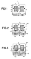
- the transformer 1 in FIG. 1 comprises a magnetic circuit consisting of two ferrite half-circuits 2, 3 having, in section, a shape of "E".
- the winding carcass 4 of the transformer 1 carries a coil 5 comprising one or more electrically separate windings.
- the magnetic circuit and the coil carcass are assembled by gluing. This bonding consists in injecting glue into the air gap 6, in the space 7 between the walls of the axial hole of the carcass 4 and the inner legs 8, 9 of the magnetic half-circuits 2, 3, and in the spaces 10 , 11 between the opposite faces of the outer legs of circuits 2, 3.
- Such an assembly makes it possible to guarantee good mechanical strength of the magnetic circuit and of the coil, but only if the thermal variations to which the transformer 1 is subjected are not too large and rapid. Indeed, if the transformer were subjected to "thermal shocks" of the type mentioned in the preamble, they cause faults in the ferrites due to coefficients of thermal expansion that are substantially different from the ferrite and the glue.
- the present invention proposes, according to the embodiment of FIG. 2, to carry out the assembly of the magnetic circuit 2, 3 and the carcass 4 of the transformer 1A differently. Bonding of the magnetic circuit with respect to the carcass 4 is carried out only at the points 10 and 11 above and on the outer face of a cheek 12 of the carcass 4 (glue points 12A, 12B).
- This cheek 12 is that which is on the side of the lower magnetic half-circuit 3 and of the base 13 for fixing the transformer and for the electrical connection of its windings.
- the glue is the one usually used.
- the air gap 14 between the legs 8, 9 is then empty, that is to say that it is an air air gap. It absorbs the mechanical stresses due to thermal shocks, which means that there is no longer any risk of cracking of the ferrites.
- the air gap generates magnetostriction noises which result in audible snoring.
- the embodiment of FIG. 3 makes it possible to very significantly reduce these magnetostriction noises.
- the transformer 1B in FIG. 3 is produced in the same way as the transformer 1A in FIG. 2, but its air gap determined by the legs 8, 9 is filled with an absorbent material 15 of the family of silicones.
- the material 15 is deposited in the pasty state on the leg 9 of the lower magnetic half-circuit 3, in a thickness slightly greater than the nominal thickness that the air gap should have.
- the transformer is assembled as in the case of FIG. 2, that is to say in particular with the dots of glue 10, 11, 12A, 12B.
- the material 15 is an already hardened tablet which is deposited between the legs 8, 9.
- the thickness of this tablet must be approximately a few tenths of a millimeter greater than the nominal thickness of the air gap.
- the surface of its faces in contact with the legs 8, 9 must be greater than about a quarter of the surface of the faces opposite the legs and at most equal to the surface of these faces.
- this silicone material also has the advantage of making it possible to reduce the operating temperature of the ends of the legs 8, 9 thanks to the good thermal conductivity of the silicone.
- the magnetic circuit can therefore admit a higher maximum operating temperature.
Landscapes
- Engineering & Computer Science (AREA)
- Power Engineering (AREA)
- Chemical & Material Sciences (AREA)
- Composite Materials (AREA)
- Coils Or Transformers For Communication (AREA)
Abstract
Description
- La présente invention a pour objet un transformateur à circuit magnétique en ferrite résistant aux chocs thermiques.
- Les alimentations à découpage fonctionnant en mode à accumulation "flyback" nécessitent un stockage d'énergie dans le circuit magnétique en double "E" en ferrite du transformateur avant transfert de cette énergie vers le circuit électrique branché en aval du transformateur. Ce stockage d'énergie impose l'utilisation d'un circuit magnétique à entrefer. De façon classique, l'assemblage du circuit magnétique et de la bobine se fait par collage des jambes extérieures du circuit magnétique ainsi que de l'entrefer.
- Un tel procédé de réalisation de transformateurs permet de garantir une bonne tenue mécanique du circuit magnétique et de la bobine, mais ne satisfait pas les exigences de résistance aux contraintes thermiques imposées par les normes en vigueur (par exemple dix cycles de chocs thermiques avec séjour à - 25° C pendant 30mn, passage brusque, en quelques secondes à + 85° C, et séjour de 30mn à cette dernière température, etc.). En effet, les coefficients de dilatation thermique différents du circuit magnétique et du point de colle au niveau de l'entrefer générent alors des failles dans la ferrite du circuit magnétique.
- Pour éviter la formation de telles failles dans la ferrite, on pourrait prévoir un entrefer à air, en collant la bobine au circuit magnétique. L'entrefer à air absorberait les contraintes mécaniques provoquées par les essais thermiques, mais génèrerait des phénomènes magnétostrictifs se traduisant par des ronflements audibles dans les transformateurs, la magnétostriction étant un phénomène de déformation élastique lié à l'aimantation.
- La présente invention a pour objet un transformateur du type à circuit magnétique ferrite à section en forme de double "E", dont le circuit magnétique puisse résister aux contraintes thermiques du type précité, et qui ne soit pas le siège de bruits de magnéto striction.
- Le transformateur conforme à l'invention comporte, outre un collage des jambes extérieures du circuit magnétique, un collage entre carcasse de bobine et circuit magnétique au niveau de l'embase de la bobine. Selon une autre caractéristique de l'invention, on dispose dans l'entrefer des jambes centrales un matériau de la famille des silicones. Ce matériau peut être déposé à l'état pâteux ou sous forme d'une pastille ayant une épaisseur supérieure de quelques dixièmes de millimètre à l'épaisseur nominale de l'entrefer.
- La présente invention sera mieux comprise à la lecture de la description détaillée de deux modes de réalisation pris comme exemples non limitatifs et illustrés par le dessin annexé, sur lequel :
- - la figure 1 est une vue en coupe d'un transformateur à circuit magnétique en double "E", réalisé selon la technique de l'art antérieur ;
- - la figure 2 est une vue en coupe d'un transformateur du type de celui de la figure 1, réalisé selon un premier mode de réalisation de l'invention, et
- - la figure 3 est une vue en coupe d'un transformateur du type de celui de la figure 1, réalisé selon un mode de réalisation préféré de l'invention.
- Le transformateur 1 de la figure 1 comporte un circuit magnétique se composant de deux demi-circuits en ferrite 2, 3 ayant, en coupe, une forme de "E". La carcasse 4 de bobinage du transformateur 1 porte une bobine 5 comportant un ou plusieurs enroulements électriquement séparés. L'assemblage du circuit magnétique et de la carcasse de la bobine se fait par collage. Ce collage consiste à injecter de la colle dans l'entrefer 6, dans l'espace 7 entre les parois du trou axial de la carcasse 4 et les jambes intérieures 8, 9 des demi-circuits magnétiques 2, 3, et dans les espaces 10, 11 entre les faces en regard des jambes extérieures des circuits 2, 3.
- Un tel assemblage permet de garantir une bonne tenue mécanique du circuit magnétique et de la bobine, mais seulement si les variations thermiques auxquelles est soumis le transformateur 1 ne sont pas trop amples et rapides. En effet, si l'on faisait subir au transformateur des "chocs thermiques" du type cité en préambule, ils provoquent des failles dans les ferrites à cause de coefficients de dilatation thermique sensiblement différents de la ferrite et de la colle.
- Pour résoudre ce problème de résistance aux chocs thermiques, la présente invention propose, selon le mode de réalisation de la figure 2, de réaliser différemment l'assemblage du circuit magnétique 2, 3 et de la carcasse 4 du transformateur 1A. Le collage du circuit magnétique par rapport à la carcasse 4 est effectué uniquement aux points 10 et 11 précités et sur la face extérieure d'une joue 12 de la carcasse 4 (points de colle 12A, 12B). Cette joue 12 est celle qui est du côté du demi-circuit magnétique inférieur 3 et de l'embase 13 de fixation du transformateur et de raccordement électrique de ses enroulements. La colle est celle habituellement utilisée.
- L'entrefer 14 entre les jambes 8, 9 est alors vide, c'est-à-dire que c'est un entrefer à air. Il absorbe les contraintes mécaniques dues aux chocs thermiques, ce qui fait qu'il n'y a plus de risques de fissuration des ferrites.
- Cependant, l'entrefer à air génère des bruits de magnétostriction qui se traduisent par des ronflements audibles.
- Le mode de réalisation de la figure 3 permet de diminuer très sensiblement ces bruits de magnétostriction. Le transformateur 1B de la figure 3 est réalisé de la même façon que le transformateur 1A de la figure 2, mais son entrefer déterminé par les jambes 8, 9 est rempli d'un matériau absorbeur 15 de la famille des silicones. Selon ce mode de réalisation de la figure 3, le matériau 15 est déposé à l'état pâteux sur la jambe 9 du demi-circuit magnétique inférieur 3, en une épaisseur légèrement supérieure à l'épaisseur nominale que devrait avoir l'entrefer. Avant durcissement de cette pâte, on assemble le transformateur comme dans le cas de la figure 2, c'est-à-dire en particulier avec les points de colle 10, 11, 12A, 12B.
- Selon une variante, le matériau 15 est une pastille déjà durcie que l'on dépose entre les jambes 8, 9. L'épaisseur de cette pastille doit être supérieure d'environ quelques dixièmes de millimètres à l'épaisseur nominale de l'entrefer. La surface de ses faces en contact avec les jambes 8, 9 doit être supérieure au quart environ de la surface des faces en regard des jambes et au maximum égale à la surface de ces faces.
- L'utilisation de ce matériau siliconé présente en outre l'avantage de permettre de diminuer la température de fonctionnement des extrémités des jambes 8, 9 grâce à la bonne conductibilité thermique du silicone. Le circuit magnétique peut donc alors admettre une plus grande température maximale de fonctionnement.
Claims (6)
Applications Claiming Priority (2)
| Application Number | Priority Date | Filing Date | Title |
|---|---|---|---|
| FR8715202 | 1987-11-03 | ||
| FR8715202A FR2622732B1 (fr) | 1987-11-03 | 1987-11-03 | Transformateur a circuit magnetique en ferrite resistant aux chocs thermiques |
Publications (2)
| Publication Number | Publication Date |
|---|---|
| EP0315527A1 true EP0315527A1 (fr) | 1989-05-10 |
| EP0315527B1 EP0315527B1 (fr) | 1993-05-19 |
Family
ID=9356419
Family Applications (1)
| Application Number | Title | Priority Date | Filing Date |
|---|---|---|---|
| EP19880402752 Expired - Lifetime EP0315527B1 (fr) | 1987-11-03 | 1988-11-03 | Transformateur à circuit magnétique en ferrite résistant aux chocs thermiques |
Country Status (5)
| Country | Link |
|---|---|
| EP (1) | EP0315527B1 (fr) |
| DE (1) | DE3881158T2 (fr) |
| ES (1) | ES2041326T3 (fr) |
| FR (1) | FR2622732B1 (fr) |
| SG (1) | SG9595G (fr) |
Cited By (4)
| Publication number | Priority date | Publication date | Assignee | Title |
|---|---|---|---|---|
| EP0461712A1 (fr) * | 1990-06-14 | 1991-12-18 | Koninklijke Philips Electronics N.V. | Transformateur avec un entrefer et un paquet de feuilles isolantes |
| EP0390643B1 (fr) * | 1989-03-28 | 1994-04-20 | OREGA ELECTRONIQUE & MECANIQUE | Transformateur du type à circuit magnétique fermé en ferrite |
| EP0818791A1 (fr) * | 1996-07-09 | 1998-01-14 | Deutsche Thomson-Brandt Gmbh | Transformateur haute tension |
| EP0907190A3 (fr) * | 1997-09-29 | 2000-07-12 | Epcos Ag | Composant inductif et son procédé de fabrication |
Families Citing this family (1)
| Publication number | Priority date | Publication date | Assignee | Title |
|---|---|---|---|---|
| DE102011116861A1 (de) | 2011-10-25 | 2013-04-25 | Epcos Ag | Elektronisches Bauelement zur Führung eines Magnetfeldes |
Citations (4)
| Publication number | Priority date | Publication date | Assignee | Title |
|---|---|---|---|---|
| FR1380363A (fr) * | 1964-01-28 | 1964-11-27 | Siemens Ag | Bobine électrique avec un noyau de ferrite en coquille |
| DE2404603A1 (de) * | 1974-01-31 | 1975-08-07 | Crl Electronic Bauelemente | Auf einen vorgegebenen induktivitaetswert einstellbare induktivitaet |
| GB2039156A (en) * | 1978-11-29 | 1980-07-30 | Hitachi Ltd | Transformer |
| DE8609584U1 (de) * | 1986-04-09 | 1987-08-06 | Philips Patentverwaltung GmbH, 22335 Hamburg | Transformator oder Drossel für durch Takten mit einer Taktfrequenz intermittierenden Betrieb |
-
1987
- 1987-11-03 FR FR8715202A patent/FR2622732B1/fr not_active Expired - Lifetime
-
1988
- 1988-11-03 ES ES88402752T patent/ES2041326T3/es not_active Expired - Lifetime
- 1988-11-03 EP EP19880402752 patent/EP0315527B1/fr not_active Expired - Lifetime
- 1988-11-03 DE DE19883881158 patent/DE3881158T2/de not_active Expired - Fee Related
-
1995
- 1995-01-21 SG SG9595A patent/SG9595G/en unknown
Patent Citations (4)
| Publication number | Priority date | Publication date | Assignee | Title |
|---|---|---|---|---|
| FR1380363A (fr) * | 1964-01-28 | 1964-11-27 | Siemens Ag | Bobine électrique avec un noyau de ferrite en coquille |
| DE2404603A1 (de) * | 1974-01-31 | 1975-08-07 | Crl Electronic Bauelemente | Auf einen vorgegebenen induktivitaetswert einstellbare induktivitaet |
| GB2039156A (en) * | 1978-11-29 | 1980-07-30 | Hitachi Ltd | Transformer |
| DE8609584U1 (de) * | 1986-04-09 | 1987-08-06 | Philips Patentverwaltung GmbH, 22335 Hamburg | Transformator oder Drossel für durch Takten mit einer Taktfrequenz intermittierenden Betrieb |
Cited By (4)
| Publication number | Priority date | Publication date | Assignee | Title |
|---|---|---|---|---|
| EP0390643B1 (fr) * | 1989-03-28 | 1994-04-20 | OREGA ELECTRONIQUE & MECANIQUE | Transformateur du type à circuit magnétique fermé en ferrite |
| EP0461712A1 (fr) * | 1990-06-14 | 1991-12-18 | Koninklijke Philips Electronics N.V. | Transformateur avec un entrefer et un paquet de feuilles isolantes |
| EP0818791A1 (fr) * | 1996-07-09 | 1998-01-14 | Deutsche Thomson-Brandt Gmbh | Transformateur haute tension |
| EP0907190A3 (fr) * | 1997-09-29 | 2000-07-12 | Epcos Ag | Composant inductif et son procédé de fabrication |
Also Published As
| Publication number | Publication date |
|---|---|
| DE3881158T2 (de) | 1993-11-18 |
| ES2041326T3 (es) | 1993-11-16 |
| DE3881158D1 (de) | 1993-06-24 |
| EP0315527B1 (fr) | 1993-05-19 |
| FR2622732A1 (fr) | 1989-05-05 |
| FR2622732B1 (fr) | 1990-08-03 |
| SG9595G (en) | 1995-06-16 |
Similar Documents
| Publication | Publication Date | Title |
|---|---|---|
| WO2009148072A1 (fr) | Inductance en puce et procédé de fabrication de celle-ci | |
| EP0315527B1 (fr) | Transformateur à circuit magnétique en ferrite résistant aux chocs thermiques | |
| EP1019926B1 (fr) | Composant inductif et procede de fabrication d'un tel composant | |
| EP0390643B1 (fr) | Transformateur du type à circuit magnétique fermé en ferrite | |
| WO1987003736A1 (fr) | Circuit magnetique a faible champ magnetique rayonne, en particulier pour un transformateur haute tension alimentant un tube cathodique | |
| FR2508250A1 (fr) | Ensemble bobine-noyau a ajustement par serrage et son procede de fabrication pour moteur electrique du type pas a pas | |
| EP0660339A1 (fr) | Perfectionnement aux transformateurs du type à circuit magnétique fermé en ferrite | |
| FR2954573A1 (fr) | Transformateur planaire de puissance. | |
| FR2777410A1 (fr) | Dispositif formant thermoplongeur pouvant etre utilise notamment dans un radiateur de chauffage a circulation d'eau | |
| WO1998010447A1 (fr) | Transformateur haute tension/basse tension a isolation seche thermoplastique | |
| EP0109899A1 (fr) | Module préadapté pour diode hyperfréquence à forte dissipation thermique | |
| EP0204636A1 (fr) | Condensateur à fort courant, et procédé de réalisation d'un tel condensateur | |
| FR2663452A3 (fr) | Noyau de ferrite mince a trois branches pour dispositifs electroniques. | |
| FR2746974A1 (fr) | Connecteur de liaison | |
| JP2523914B2 (ja) | 変成器 | |
| FR2843650A1 (fr) | Procede de bobinage de transformateurs | |
| FR2657223A1 (fr) | Systeme de montage d'un transistor avec refroidisseur. | |
| FR2835646A1 (fr) | Tore magnetique nanocristallin | |
| FR2673483A1 (fr) | Composant magnetique pour le report a plat. | |
| FR3155086A1 (fr) | Transformateur planaire comportant un noyau magnétique comprenant deux matériaux différents | |
| BE1003605A5 (fr) | Liaison de deux elements bons conducteurs de chaleur par l'intermediaire d'un element mauvais conducteur de chaleur. | |
| FR2536598A1 (fr) | Bloc a condensateurs electriques pour la correction du facteur de puissance | |
| FR3089367A1 (fr) | Convertisseur ac/dc | |
| FR3164836A1 (fr) | Element capacitif, ensemble pour module de puissance, et procede de fabrication correspondant. | |
| FR2681496A1 (fr) | Elements chauffants blindes a alimentation electrique, et procede de fabrication de tels elements. |
Legal Events
| Date | Code | Title | Description |
|---|---|---|---|
| PUAI | Public reference made under article 153(3) epc to a published international application that has entered the european phase |
Free format text: ORIGINAL CODE: 0009012 |
|
| AK | Designated contracting states |
Kind code of ref document: A1 Designated state(s): DE ES GB IT |
|
| 17P | Request for examination filed |
Effective date: 19891019 |
|
| 17Q | First examination report despatched |
Effective date: 19920525 |
|
| GRAA | (expected) grant |
Free format text: ORIGINAL CODE: 0009210 |
|
| AK | Designated contracting states |
Kind code of ref document: B1 Designated state(s): DE ES GB IT |
|
| ITF | It: translation for a ep patent filed | ||
| REF | Corresponds to: |
Ref document number: 3881158 Country of ref document: DE Date of ref document: 19930624 |
|
| GBT | Gb: translation of ep patent filed (gb section 77(6)(a)/1977) |
Effective date: 19930713 |
|
| REG | Reference to a national code |
Ref country code: ES Ref legal event code: FG2A Ref document number: 2041326 Country of ref document: ES Kind code of ref document: T3 |
|
| PLBE | No opposition filed within time limit |
Free format text: ORIGINAL CODE: 0009261 |
|
| STAA | Information on the status of an ep patent application or granted ep patent |
Free format text: STATUS: NO OPPOSITION FILED WITHIN TIME LIMIT |
|
| 26N | No opposition filed | ||
| REG | Reference to a national code |
Ref country code: GB Ref legal event code: IF02 |
|
| PGFP | Annual fee paid to national office [announced via postgrant information from national office to epo] |
Ref country code: GB Payment date: 20061009 Year of fee payment: 19 |
|
| PGFP | Annual fee paid to national office [announced via postgrant information from national office to epo] |
Ref country code: DE Payment date: 20061117 Year of fee payment: 19 |
|
| PGFP | Annual fee paid to national office [announced via postgrant information from national office to epo] |
Ref country code: ES Payment date: 20061123 Year of fee payment: 19 |
|
| PGFP | Annual fee paid to national office [announced via postgrant information from national office to epo] |
Ref country code: IT Payment date: 20061130 Year of fee payment: 19 |
|
| GBPC | Gb: european patent ceased through non-payment of renewal fee |
Effective date: 20071103 |
|
| PG25 | Lapsed in a contracting state [announced via postgrant information from national office to epo] |
Ref country code: DE Free format text: LAPSE BECAUSE OF NON-PAYMENT OF DUE FEES Effective date: 20080603 |
|
| PG25 | Lapsed in a contracting state [announced via postgrant information from national office to epo] |
Ref country code: GB Free format text: LAPSE BECAUSE OF NON-PAYMENT OF DUE FEES Effective date: 20071103 |
|
| REG | Reference to a national code |
Ref country code: ES Ref legal event code: FD2A Effective date: 20071105 |
|
| PG25 | Lapsed in a contracting state [announced via postgrant information from national office to epo] |
Ref country code: ES Free format text: LAPSE BECAUSE OF NON-PAYMENT OF DUE FEES Effective date: 20071105 |
|
| PG25 | Lapsed in a contracting state [announced via postgrant information from national office to epo] |
Ref country code: IT Free format text: LAPSE BECAUSE OF NON-PAYMENT OF DUE FEES Effective date: 20071103 |