EP0316002A2 - Méthode de direction d'un véhicule - Google Patents
Méthode de direction d'un véhicule Download PDFInfo
- Publication number
- EP0316002A2 EP0316002A2 EP88118827A EP88118827A EP0316002A2 EP 0316002 A2 EP0316002 A2 EP 0316002A2 EP 88118827 A EP88118827 A EP 88118827A EP 88118827 A EP88118827 A EP 88118827A EP 0316002 A2 EP0316002 A2 EP 0316002A2
- Authority
- EP
- European Patent Office
- Prior art keywords
- steer
- angle
- steering
- wheel
- steer angle
- Prior art date
- Legal status (The legal status is an assumption and is not a legal conclusion. Google has not performed a legal analysis and makes no representation as to the accuracy of the status listed.)
- Granted
Links
- 238000000034 method Methods 0.000 title claims abstract description 30
- 238000001514 detection method Methods 0.000 claims 1
- 230000004044 response Effects 0.000 abstract description 2
- 239000012530 fluid Substances 0.000 description 14
- 230000004043 responsiveness Effects 0.000 description 6
- 230000001133 acceleration Effects 0.000 description 5
- 230000000694 effects Effects 0.000 description 2
- 238000011144 upstream manufacturing Methods 0.000 description 2
- 239000006096 absorbing agent Substances 0.000 description 1
- 230000006866 deterioration Effects 0.000 description 1
- 230000002542 deteriorative effect Effects 0.000 description 1
- 238000010586 diagram Methods 0.000 description 1
- 239000012212 insulator Substances 0.000 description 1
- 230000000717 retained effect Effects 0.000 description 1
- 230000035939 shock Effects 0.000 description 1
Images


Classifications
-
- B—PERFORMING OPERATIONS; TRANSPORTING
- B62—LAND VEHICLES FOR TRAVELLING OTHERWISE THAN ON RAILS
- B62D—MOTOR VEHICLES; TRAILERS
- B62D7/00—Steering linkage; Stub axles or their mountings
- B62D7/06—Steering linkage; Stub axles or their mountings for individually-pivoted wheels, e.g. on king-pins
- B62D7/14—Steering linkage; Stub axles or their mountings for individually-pivoted wheels, e.g. on king-pins the pivotal axes being situated in more than one plane transverse to the longitudinal centre line of the vehicle, e.g. all-wheel steering
Definitions
- the present invention relates to a method of steering a vehicle, of such a kind that the front and rear wheels are both secondarily steerable in addition to a main steer of the front wheels.
- both the front and rear wheels are secondarily steerable, it is known to maintain the yaw rate and lateral acceleration unchanged irrespectively of the speed of rotation of the steering wheel by making flat the frequency characteristics of the yaw rate and lateral acceleration relative to the steering frequency through control of the respective secondary steer angles.
- the passenger or passengers can always feel the same yaw rate and lateral acceleration and therefore can be free from an otherwise caused uneasiness at the begining of cornering.
- Tf, Kr and Tf are set to be positive whereas Tr is set to be negative. Due to this, just after the moment t1 at which the rotation of the steeering wheel begins, the rear wheel secondary steer angle ⁇ r exhibited by the formula (3) becomes once (until the moment t2) to be of such a phase opposite to that of the front wheels and thereafter returns to be of the same phase as the front wheels as is apparent from Fig. 10 in which the rear wheel secondary steer angle ⁇ r is shown together with Kr ⁇ and Tr ⁇ . For this reason, the vehicle steering system is required to perform a complicated control and therefore the system becomes complicated, resulting in a problem of a high cost. Further, the system is required to have a high responsiveness, thus further increasing the cost.
- an improved method of steering a vehicle having a set of steerable front wheels and a set of steerable rear wheels which are both secondarily steered upon main steering of the front wheels by a steering wheel comprises providing to the front wheels a secondary steer angle corresponding to at least a differentiated value of a steering wheel operation in such away as to increase an overall steer angle of the front wheels and providing to the rear wheels a secondary steer angle proportional to the steering wheel operation and of the same phase as the steer angle of the front wheels.
- the above described providing of the secondary steer angle to the rear wheels is performed with a time-lag of a first order.
- This method is effective for solving the above noted problems inherent in the prior art vehicle steering. That is, the present invention attaches much importance to the vehicle head turning characteristic or the vehicle turning responsiveness than to the above described flat frequency characteristic of the yaw rate and lateral acceleration and aims at solving the above problem in exchange of only a little deterioration or sacrifice of a vehicle perofrmance characteristic.
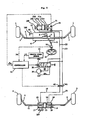
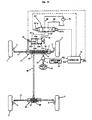
- a set of front wheels are indicated by the reference numerals 1 and 1 and a set of rear wheels are indicated by the reference numerals 2 and 2.
- the front wheels 1 and 1 are steerably installed on a vehicle body 100 by means of steering knuckles 3 and 3.
- the rear wheels 2 and 2 are steerably installed on the vehicle body 100 by means of steering knuckles 4 and 4.
- the steering knuckles 3 and 3 are interconnected by a tie rod 5 to which a rack 7 is fixedly attached to move together therewith.
- a pinion 8 meshing the rack 7 to constitute a front wheel steering gear 6 is connected to a steering wheel 10 by way of a steering shaft 9.
- the steering knuckles 4 and 4 are interconnected by a tie rod 11 to which a piston 13 of an actuator 12 for rear wheel steer is fixedly attached or installed to move together therewith.
- a cylinder 14 of the actuator 12 is fixedly installed on the vehicle body 100.
- the piston 13 is resiliently held in a center actuator position by means of springs 17 and 18 disposed within chambers 15 and 16, respectively.
- a gear casing 19 of the front wheel steering gear 6 is not fixed to the vehicle body 100 but resiliently supported by an insulator 20 in such a way as to be longitudinally movable by at least an amount corresponding to a maximum secondary steer of the front wheels 1 and 1.
- An actuator 21 is provided bertween the gear casing 19 and the vehicle body 100 for enabling the gear casing 19 to effect the above longitudinal movement.
- the actuator 21 is constructed so that a piston 21a is held in a center actuator position by means of springs 21d and 21e disposed in chambers 21b and 21c on the opposite sides of the piston 21a, respectively.
- Conduits 22 and 23 respectively communicated with the chambers 21b and 21c and conduits 24 and 25 respectively communicated with the chambers 15 and 16 are connected by way of solenoid controlled valves 26 and 27 to a supply conduit 28 and a drain conduit 29, respectively.
- the supply conduit 28 is communicated with an outlet port of a pump 30 so as to be always supplied with a fluid pressure discharged by the pump 30.
- the solenoid controlled valves 26 and 27 are three position directional control valves and of the electromagnetically proportional type so as to have two step positions depending on energization of solenoids 26a and 27a, respectively.
- the solenoids 26a and 27a When the solenoids 26a and 27a are de-energized, the valves 26 and 27 obstruct communication of the conduits 22-25 with the supply conduit 28 and drain conduit 29 so that the actuators 12 and 21 are held in their having displaced positions, i.e., their pistons 13 and 21a are held stationary in the positions into which they have been moved.
- the conduits 22 and 24 are communicated with the supply conduit 28 whilst the conduits 23 and 25 with the drain conduit 29 for thereby causing the actuator pistons 13 and 21a to move in the right-hand direction in the drawing.
- the solenoids 26a and 27a are energized to allow the valves 26 and 27 to take their second step positions, the conduits 22 and 24 are communicated with the drain conduit 29 whilst the conduits 23 and 25 with the supply conduit 28 for thereby causing the actuator pistons 12 and 21a to move in the left-hand direction in the drawing.
- Energization and de-energization of the solenoids 26a, 27a are controlled by a secondary steer controller 31.
- the controller 31 receives from a steer angle sensor 32 a signal which represents a steer angle ⁇ of the steering handle 10 and from a vehicle speed sensor 33 a signal which represents a vehicle speed V.
- the controller 31 further receives from stroke sensors 34 and 35 signals which represent strokes or movements of the actuator pistons 13 and 21a, i.e., a front wheel secondary steer actual angle ⁇ F and a rear reel secondary steer actual angle ⁇ R for feedback control of the front and rear secondary steer.
- the controller 31 determines a front wheel secondary steer target angle ⁇ f and a rear wheel secondary steer target angle ⁇ r based on the input informations ⁇ and V.
- the controller 31 controls energization and de-energization of the solenoids 26a and 27a independently so that the secondary steer target angles and the secondary steer actual angles correspond to each other. In this manner, the gear casing 19 and the tie rod 11 are moved by the actuators 12 and 21 under control of the controller 31, whereby to perform a secondary steer of the front and rear wheels 1, 1 and 2, 2.
- Rotation of the steering wheel 10 causes the steering shaft 9 and therefore the pinion 8 to rotate.
- Roation of the pinion 8 causes the rack 7 to make a stroke or move longitudinally for thereby causing the front wheels 1 and 1 to be steered in the corresponding direction by way of the steering knuckles 3 and 3, whereby to steer a vehicle to the corresponding direction.
- the controller 31 determines, based on the steer angle ⁇ of the steering wheel 10 and the vehicle speed V detected by the sensors 32 and 33, a front wheel secondary steer target angle ⁇ f by computation of the following formula, and a rear wheel target secondary steer angle ⁇ r by computation of the following formula, where ⁇ is a time constant.
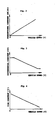
- the proportional constants Kf and Kr are set to be of such functions of vehicle speed V as shown in Fig. 2, the differential constants Tf is set to be of such a function of vehicle speed V as shown in Fig. 3, and the time constant ⁇ is set to be of such a function of vehicle speed V as shown in Fig. 4.
- the differential constant Kf, differential constant Tf and time constant ⁇ are obtained from those functions, and based on the thus obtained constants together with the steer angle ⁇ of the steering wheel 10 and its differentiated value and by using the formulas (4) and (5), the controller 31 computes the front wheel secondary steer target angle ⁇ r and the rear wheel secondary steer target angle ⁇ r.
- the solenoid controlled valve 26 supplies fluid pressure from the pump 30 to one of the conduits 22 and 23 and at the same time drains the other of the same.
- the actuators 21 and 12 cause the pistons 21a and 13 to move in the corresponding direction for thereby moving the gear casing 19 and the tie rod 11 in the corresponding direction, whereby to secondarily steer the front wheels 1 and 1 and the rear wheels 2 and 2 by the target values ⁇ f and ⁇ r.
- the controller 31 makes the solenoids 26a and 27a de-energized for thereby holding the actuators 21 and 12 in their having controlled positions.
- the front wheel secondary steer target angle ⁇ f is griven by the formula (4)
- the front wheels 1 and 1 are increasedly steered by the angle corresponding to the angular velocity of rotation of the steering wheel 10 and the differential constant Tf in addition to the angle corresponding to the steer angle ⁇ of the steering wheel 10 and the proportional constant Kf, whereby the front wheel secondary steer can be done by the so-called proportional control and differential control for improving the turning movement of the vehicle head (i.e., the cornering responsiveness).
- the rear wheels 2 and 2 are secondarily steered by the angle proportional (proportional constant Kr) to the steer angle ⁇ of the steering wheel 10 in the same direction as the front wheels 1 and 1, whereby the rear wheel secondary steer is done by the so-called proportional control for thereby improving the cornering stability of the vehicle.
- the above described rear wheel secondary steer is performed with a time-lag of a first order corresponding to the time constant ⁇ , thus making it possible to eliminate such an otherwise caused uncomfortatable feel that a vehicle first slides laterally or sideways and thereafter starts turning.
- the steering system is not required to perform a complicated control and therefore can be simple in structure, thus making it possible to reduce the cost. Furthermore, the system is not required to have a high responsiveness, thus being further advantageous in view of the cost.
- Fig. 5 shows another steering system capable of carrying out the method of this invention.
- parts and portions like or corresponding to those of the steering system of Fig. 1 are designated by the same reference numerals.
- the fluid pressure supplied through the conduits 22 and 23 to the actuator 21 for front wheel secondary steer is also used for rear wheel secondary steer.
- the conduits 24 and 25 communicated with the chambers 15 and 16 of the actuator 12 for rear wheel steer and extending therefrom are connected to the conduits 22 and 23, and variable orifices 40 and 41 are disposed in the conduits 24 and 25.
- the degree of opening of the variable orifices 40 and 41 are commonly controlled by the controller 31 and determined so that the same rear wheel secondary steer as the previous embodiment is obtained.
- the controller 31 determines the degree of opening of the variable orifices 40 and 41 for obtaining the rear wheel secondary steer target angle which is determined in the above described manner in relation to the fluid pressure for front wheel secondary steer, whereby to control the fluid pressure for rear wheel secondary steer to be supplied to the actuator 12.
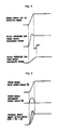
- the rear wheels 2 and 2 can be secondarily steered similarly to the previous example with a time-lag of a first order as indicated by ⁇ T in Fig. 6.
- Fig. 7 shows a further steering system capable of carrying out the method of this invention, in which parts and portions like or corresponding to those of the previous steering system of Fig. 1 are designated by the same reference numerals. Since the above improvement in the vehicle head turning characteristic can be attained even if the front wheel secondary steer is performed by the derivative control only, this steering system is structured so as to connect the conduits 22 and 23 extending from the chambers 21b and 21c of the actuator 21 to the chambers 52 and 53 of the servo valves 50 separated by the piston 51.
- the servo valve 50 has a valve body 54 secured to the vehicle body 100 and a valve spool 55 slidably disposed in the piston 51 and fixed to the tie rod 5.
- the valve body 54 has fixed thereto a guide piston 56 which is in turn slidably disposed within the servo piston 51 to define chambers 51a and 51b.
- Springs 57a and 57b are disposed within the chambers 51a and 51b for resiliently holding the servo piston 51 in the center valve position.
- inlet valves 58a and 58b and outlet valves 59a and 59b there are formed inlet valves 58a and 58b and outlet valves 59a and 59b, and a portion between the inlet valves 58a and 58b is communicated with the supply conduit 28.
- the upstream sides of the outlet valves 59a and 59b are respectively communicated with the corresponding chambers 51a and 51b and also with the corresponding chambers 15 and 16 of the actuator 12 for rear wheel steer through the conduits 24 and 25 in which the variable orifices 40 and 41 are disposed, and the downstream sides of the outlet valves 59a and 59b are communicated with the drain conduit 29.
- the two chambers 21b and 21c of the actuator 21 are communicated with each other by a conduit 61.
- a variable orifice 62 is disposed in the conduit 61 so that the communication between the chambers 21b and 21c is determined by the degree of opening of the variable orifice 52.
- the variable orifice 62 is controlled in its degree of opening by the controller 31 which also controls the degree of opening of the variable orifices 40 and 41 as mentioned above.
- the controller 31 increases the degree of opening of the variable orifice 62 as the vehicle speed V increases.
- the chambers 21b, 21c, 52 and 53 and the conduits 22 and 20 are filled with incompressible fluid.
- the front wheel secondary steer of this embodiment is performed as follows. Upon steering of the vehicle to the left in which the tie rod 5 is moved rightwards, the plunger 55 moves rightwards reducing the degree of opening of the valve portions 58a and 59b. By this, such a pressure differential that the fluid pressure in the chamber 51b is higher while the fluid pressure in the chamber 51a is lower is caused between the chambers 51a and 51b, thus causing the servo piston 51 to move in response to movement of the plunger 55 while overcoming the bias of the springs 57a and 57b. By the rightward movement of the servo piston 51, fluid is caused to flow from the chamber 52 to the chamber 53 through the conduit 22, chamber 21b, variable orifice 62, chamber 21c and the conduit 23.
- variable orifice 62 offers a resistance based on its degree of opening, and a fluid pressure in accordance with the orifice opening and the rate of fluid flow is produced on the upstream side of the variable orifice 62, i.e., within the chambers 21b or 21c, thus causing the actuator piston 21a and therefore the gear casing 19 to move rightwards or leftwards for thereby increasing the steer angle of the front wheels 1 and 1.
- the actuator 21 between the moments t1 and t2 where the steer angle ⁇ is changing, causes the front wheels 1 and 1 to effect a seconary steer in the steer angle increasing direction and by the angle corresponding to the steering wheel rotation speed and the degree of opening of the variable orifice 62. While this causes the front wheel overall steer angle ⁇ F to be increased by the amount indicated by the hatched portion in Fig.
- the rear wheel secondary steer in this embodiment will no be described.
- the pressure differential between the chambers 51a and 51b is also caused between the chambers 15 and 16 of the actuator 12, thus causing the rear wheels 2 and 2 to be steered in the same directions by the higher pressure in the chamber 16 in case of steering of the vehicle to the left and by the higher pressure in the chamber 15 in case of steering of the vehicle to the right, respectively.
- the orifices 40 and 41 are provided and controlled by the controller 31 in the way similar to Fig. 5, the rear wheel secondary steer can be performed with a time-lag of a first order similarly to the previous embodiment.
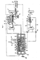
- Fig. 10 shows a further vehicle steering system capable of carrying out the method of this invention, in which parts and portions like or corresponding to those of the previous steering system of Fig. 1 are designated by the same reference numerals.
- a rack 63 constituting part of a rear wheel steering gear 64 is fixedly attached to the tie rod 11 interconnecting the steering knuckles 4 and 4 for the rear wheels 2 and 2.
- a pinion 65 meshing with the rack 63 to constitute the steering gear 64 is connected to an end of a rear wheel steering shaft 66.
- a pinion 67 is connected to the other end of the rear wheel steering shaft 66.
- the pinion 67 is meshed with the rack 7 in such a way that their relative locations with respect to the top-to-bottom direction of the vehicle body are opposite to those of the pinion 65 and the rack 63.
- the solenoid controlled valve 26′ is of the type having two solenoids 26′a and 26′b, it is operative substantially similarly to the aforementioned solenoid 26.
- movement of the rack 7 causes the pinion 67, rear wheel steering shaft 66 and pinion 65 to rotate, thus causing the rack 63 to make a stroke or move longitudinally.
- the tie rod 11 is moved correspondingly thus causing the rear wheels 2 and 2 to be secondarily steered in the same direction or so as to be of the same phase as the front wheels 1 and 1 by way of the steering knuckles 4 and 4.
- ⁇ R Kr ⁇ ⁇ (6)
- Kr is the gear ratio of the gearing provided between the steering wheel 10 and the rack 63.
- the rear wheels 2 and 2 are secondarily steered by the angle proportional (proportional constant Kr) to the steer angle ⁇ of the steering wheel 10 and in the same direction or so as to be of the same phase as the front wheels 1 and 1, thus performing the rear wheel secondary steer by the so-called proportional control and thereby making it possible to improve the turning or cornering stability of the vehicle.
- Kr proportional constant
- the rear wheel secondary steer target angle ⁇ f is computed by multiplying the differential constant Tf which is obtained from the function in Fig. 2 and the differentiated value of the steer angle ⁇ of the steering wheel 10.
- the controller 31 determines which solenoids 26′a or 26′b is to beenergized and supplies current to the corresponding solenoid 26′a or 26′b.
- the solenoid controlled valve 26′ allows one of the conduits 22 and 23 to be supplied with fluid pressure from the pump 30 and the other conduit 22 or 23 to be drained.
- the actuator 21 causes the piston 21a to move in the corresponding direction for thereby causing the gear casing 19 to move in the corresponding direction, whereby to increase the overall steer angle of the front wheels 1 and 1, i.e., the front wheels 1 and 1 are turned by the secondary steer angle in addition to a main steer angle determined by the front wheel steering gear 6.
- the front wheels 1 and 1 are therefore secondarily steered by the steer angle corresponding to the angular velocity of the steering wheel 10 and the differential constant Tf and in the direction of increasing the overall steer angle of the front wheels 1 and 1, whereby it becomes possible to perform the secondary steer of the front wheels 1 and 1 by the so-called derivative control and thereby improve the vehicle head turning characteristic (turning responsiveness).
- Fig. 11 shows a further vehicle steering system capable of carrying out the method of this invention, in which parts and portions like or corresponding to those of the steering system of Fig. 10 are designated by the same reference numerals.
- This embodiment is a simplified form of the steering system and includes a resilient means 68 for supporting the gear casing 19 upon the vehicle body 100 and a steering damper 69 such as a shock absorber, interposed between the gear casing 19 and the vehicle body 100 in such a way as to be effective in the longitudinal direction of the resilient means 68.
- a front wheel seconary steer control responsive to vehicle speed cannot be attained, front wheels can be secondarily steered in the manner like the above described drivative control.
Landscapes
- Engineering & Computer Science (AREA)
- Chemical & Material Sciences (AREA)
- Combustion & Propulsion (AREA)
- Transportation (AREA)
- Mechanical Engineering (AREA)
- Steering-Linkage Mechanisms And Four-Wheel Steering (AREA)
Applications Claiming Priority (4)
| Application Number | Priority Date | Filing Date | Title |
|---|---|---|---|
| JP62284104A JP2531704B2 (ja) | 1987-11-12 | 1987-11-12 | 車両の操舵方法 |
| JP62284103A JP2538951B2 (ja) | 1987-11-12 | 1987-11-12 | 車両の操舵方法 |
| JP284104/87 | 1987-11-12 | ||
| JP284103/87 | 1987-11-12 |
Publications (3)
| Publication Number | Publication Date |
|---|---|
| EP0316002A2 true EP0316002A2 (fr) | 1989-05-17 |
| EP0316002A3 EP0316002A3 (en) | 1990-08-29 |
| EP0316002B1 EP0316002B1 (fr) | 1995-10-04 |
Family
ID=26555322
Family Applications (1)
| Application Number | Title | Priority Date | Filing Date |
|---|---|---|---|
| EP88118827A Expired - Lifetime EP0316002B1 (fr) | 1987-11-12 | 1988-11-11 | Méthode de direction d'un véhicule |
Country Status (3)
| Country | Link |
|---|---|
| US (1) | US4970646A (fr) |
| EP (1) | EP0316002B1 (fr) |
| DE (1) | DE3854549T2 (fr) |
Cited By (3)
| Publication number | Priority date | Publication date | Assignee | Title |
|---|---|---|---|---|
| EP1245473A3 (fr) * | 2001-03-28 | 2003-09-24 | Delphi Technologies, Inc. | Direction pour roues arrière |
| EP1529718A1 (fr) * | 2003-11-06 | 2005-05-11 | Bayerische Motoren Werke Aktiengesellschaft | Véhicule automobile avec des roues avant dirigeables et une fonction de braquage des roues arrières |
| GB2461290A (en) * | 2008-06-26 | 2009-12-30 | One80 Ltd | Rear wheel steering system. |
Families Citing this family (8)
| Publication number | Priority date | Publication date | Assignee | Title |
|---|---|---|---|---|
| US5313389A (en) * | 1988-09-13 | 1994-05-17 | Aisin Seiki Kabushiki Kaisha | Fail-safe mechanism for vehicle stability augmentation steering system |
| US5156229A (en) * | 1988-09-13 | 1992-10-20 | Aisin Seiki Kabushiki Kaisha | Steering control apparatus |
| US5220974A (en) * | 1989-03-22 | 1993-06-22 | Hyundai Motor Company | Four-wheel steering system |
| FR2684211B1 (fr) * | 1991-11-22 | 1994-02-04 | Aerospatiale Ste Nationale Indle | Dispositif d'exploitation des informations relatives aux pannes detectees par une ou plusieurs unites centrales d'un aeronef. |
| JP3211434B2 (ja) * | 1991-12-18 | 2001-09-25 | アイシン精機株式会社 | 車輛誘導制御装置 |
| DE102005013378B4 (de) * | 2005-03-23 | 2015-10-01 | Bayerische Motoren Werke Aktiengesellschaft | Kraftfahrzeug mit lenkbaren Vorderrädern und einer Lenkfunktion an den Hinterrädern |
| CN103569197B (zh) * | 2013-11-12 | 2015-08-26 | 安徽工程大学 | 四轮转向系统及其控制方法 |
| DE102015202191B4 (de) * | 2015-02-06 | 2019-07-18 | Saf-Holland Gmbh | Lenkstabilisierung |
Family Cites Families (12)
| Publication number | Priority date | Publication date | Assignee | Title |
|---|---|---|---|---|
| JPS5787759A (en) * | 1980-11-18 | 1982-06-01 | Nissan Motor Co Ltd | Method of steering vehicle |
| DE3300640A1 (de) * | 1983-01-11 | 1984-07-12 | Daimler-Benz Ag, 7000 Stuttgart | Zusatzlenkung fuer mehrachsige fahrzeuge, insbesondere personenkraftwagen |
| JPH0674052B2 (ja) * | 1984-01-31 | 1994-09-21 | 日産自動車株式会社 | 車両の操舵方法 |
| JPS60161259A (ja) * | 1984-01-31 | 1985-08-22 | Nissan Motor Co Ltd | 車両の後輪転舵装置 |
| JPS60161260A (ja) * | 1984-01-31 | 1985-08-22 | Nissan Motor Co Ltd | 車両操舵装置 |
| JPS60161265A (ja) * | 1984-01-31 | 1985-08-22 | Nissan Motor Co Ltd | 車両の操舵方法 |
| US4720790A (en) * | 1984-05-21 | 1988-01-19 | Kabushiki Kaisha Toyota Chuo Kenkyusho | Apparatus for controlling steer angle of rear wheels of vehicle |
| JPS60259571A (ja) * | 1984-06-06 | 1985-12-21 | Mazda Motor Corp | 車両の4輪操舵装置 |
| US4706771A (en) * | 1985-01-31 | 1987-11-17 | Nissan Motor Co., Ltd. | Vehicle steering control system using desired vehicle model |
| JPS628869A (ja) * | 1985-07-08 | 1987-01-16 | Mazda Motor Corp | 車両の4輪操舵装置 |
| DE3861868D1 (de) * | 1987-02-03 | 1991-04-11 | Toyoda Chuo Kenkyusho Kk | Steuervorrichtung fuer das lenken der raeder eines fahrzeugs. |
| US4828061A (en) * | 1988-06-27 | 1989-05-09 | General Motors Corporation | Closed-loop four wheel steering system having dual response rate rear steering |
-
1988
- 1988-11-10 US US07/269,698 patent/US4970646A/en not_active Expired - Lifetime
- 1988-11-11 EP EP88118827A patent/EP0316002B1/fr not_active Expired - Lifetime
- 1988-11-11 DE DE3854549T patent/DE3854549T2/de not_active Expired - Fee Related
Cited By (4)
| Publication number | Priority date | Publication date | Assignee | Title |
|---|---|---|---|---|
| EP1245473A3 (fr) * | 2001-03-28 | 2003-09-24 | Delphi Technologies, Inc. | Direction pour roues arrière |
| EP1529718A1 (fr) * | 2003-11-06 | 2005-05-11 | Bayerische Motoren Werke Aktiengesellschaft | Véhicule automobile avec des roues avant dirigeables et une fonction de braquage des roues arrières |
| GB2461290A (en) * | 2008-06-26 | 2009-12-30 | One80 Ltd | Rear wheel steering system. |
| GB2461290B (en) * | 2008-06-26 | 2012-12-05 | One80 Ltd | Rear wheel steering system |
Also Published As
| Publication number | Publication date |
|---|---|
| EP0316002B1 (fr) | 1995-10-04 |
| DE3854549D1 (de) | 1995-11-09 |
| US4970646A (en) | 1990-11-13 |
| DE3854549T2 (de) | 1996-03-14 |
| EP0316002A3 (en) | 1990-08-29 |
Similar Documents
| Publication | Publication Date | Title |
|---|---|---|
| US4473128A (en) | Vehicular power steering system | |
| US4679809A (en) | Steering control system for wheeled vehicle | |
| US5718304A (en) | Four-wheel steering system for vehicle | |
| US4690431A (en) | System for controlling cornering characteristics of wheeled vehicle | |
| US4705131A (en) | Four-wheel steering control system for vehicle | |
| US4541499A (en) | Vehicular power steering having steering effort control system | |
| US4970646A (en) | Vehicle having secondarily steered front and rear wheels | |
| US4681184A (en) | Hydraulic reaction force apparatus for power steering system | |
| US4947326A (en) | Rear wheel steer angle control system for vehicle | |
| US5150764A (en) | Vehicle rear wheel steer angle control system | |
| US5105899A (en) | Rear wheel steering angle control system for vehicles | |
| US5317513A (en) | Apparatus for actively controlling steer angle of front wheels of vehicle | |
| JP2538951B2 (ja) | 車両の操舵方法 | |
| JPH0464914B2 (fr) | ||
| JP2531704B2 (ja) | 車両の操舵方法 | |
| JP2523125B2 (ja) | 車両の舵角制御装置 | |
| JPH0344028B2 (fr) | ||
| JP2607270B2 (ja) | サスペンション装置 | |
| JP2578189B2 (ja) | 車両の補助操舵装置 | |
| JPS63106181A (ja) | 車両に使用されるパワ−・ステアリング | |
| JPH04189678A (ja) | 前輪舵角制御装置 | |
| JPS6181870A (ja) | 動力操舵制御装置 | |
| JPH0522628B2 (fr) | ||
| JPH0231977A (ja) | 後輪操舵装置 | |
| JPS61146683A (ja) | 動力操舵制御装置 |
Legal Events
| Date | Code | Title | Description |
|---|---|---|---|
| PUAI | Public reference made under article 153(3) epc to a published international application that has entered the european phase |
Free format text: ORIGINAL CODE: 0009012 |
|
| 17P | Request for examination filed |
Effective date: 19881111 |
|
| AK | Designated contracting states |
Kind code of ref document: A2 Designated state(s): DE GB |
|
| PUAL | Search report despatched |
Free format text: ORIGINAL CODE: 0009013 |
|
| AK | Designated contracting states |
Kind code of ref document: A3 Designated state(s): DE GB |
|
| 17Q | First examination report despatched |
Effective date: 19920902 |
|
| GRAA | (expected) grant |
Free format text: ORIGINAL CODE: 0009210 |
|
| AK | Designated contracting states |
Kind code of ref document: B1 Designated state(s): DE GB |
|
| REF | Corresponds to: |
Ref document number: 3854549 Country of ref document: DE Date of ref document: 19951109 |
|
| PLBE | No opposition filed within time limit |
Free format text: ORIGINAL CODE: 0009261 |
|
| STAA | Information on the status of an ep patent application or granted ep patent |
Free format text: STATUS: NO OPPOSITION FILED WITHIN TIME LIMIT |
|
| 26N | No opposition filed | ||
| REG | Reference to a national code |
Ref country code: GB Ref legal event code: IF02 |
|
| PGFP | Annual fee paid to national office [announced via postgrant information from national office to epo] |
Ref country code: DE Payment date: 20051103 Year of fee payment: 18 |
|
| PGFP | Annual fee paid to national office [announced via postgrant information from national office to epo] |
Ref country code: GB Payment date: 20051109 Year of fee payment: 18 |
|
| PG25 | Lapsed in a contracting state [announced via postgrant information from national office to epo] |
Ref country code: DE Free format text: LAPSE BECAUSE OF NON-PAYMENT OF DUE FEES Effective date: 20070601 |
|
| GBPC | Gb: european patent ceased through non-payment of renewal fee |
Effective date: 20061111 |
|
| PG25 | Lapsed in a contracting state [announced via postgrant information from national office to epo] |
Ref country code: GB Free format text: LAPSE BECAUSE OF NON-PAYMENT OF DUE FEES Effective date: 20061111 |