EP0316003A2 - Codeur de figures de lignes - Google Patents
Codeur de figures de lignes Download PDFInfo
- Publication number
- EP0316003A2 EP0316003A2 EP88118830A EP88118830A EP0316003A2 EP 0316003 A2 EP0316003 A2 EP 0316003A2 EP 88118830 A EP88118830 A EP 88118830A EP 88118830 A EP88118830 A EP 88118830A EP 0316003 A2 EP0316003 A2 EP 0316003A2
- Authority
- EP
- European Patent Office
- Prior art keywords
- line
- encoder
- symbolization
- figures
- points
- Prior art date
- Legal status (The legal status is an assumption and is not a legal conclusion. Google has not performed a legal analysis and makes no representation as to the accuracy of the status listed.)
- Withdrawn
Links
Images


Classifications
-
- G—PHYSICS
- G06—COMPUTING OR CALCULATING; COUNTING
- G06T—IMAGE DATA PROCESSING OR GENERATION, IN GENERAL
- G06T11/00—Two-dimensional [2D] image generation
- G06T11/20—Drawing from basic elements
- G06T11/23—Drawing from basic elements using straight lines or curves
-
- G—PHYSICS
- G06—COMPUTING OR CALCULATING; COUNTING
- G06K—GRAPHICAL DATA READING; PRESENTATION OF DATA; RECORD CARRIERS; HANDLING RECORD CARRIERS
- G06K11/00—Methods or arrangements for graph-reading or for converting the pattern of mechanical parameters, e.g. force or presence, into electrical signal
-
- G—PHYSICS
- G06—COMPUTING OR CALCULATING; COUNTING
- G06T—IMAGE DATA PROCESSING OR GENERATION, IN GENERAL
- G06T9/00—Image coding
- G06T9/20—Contour coding, e.g. using detection of edges
Definitions
- the present invention relates to a line figure encoder for encoding figures primarily comprised of lines, such as drawings or maps, so as to facilitate registration of such figures to computers.
- One conventional method for executing this registration of the figures is to specify each point on the figures and to represent the figures by the sets of coordinates of the specified points and to register these sets of coordinates as figure data to computers by means of a digitizer.
- this method it is necessary to specify quite a large number of points, and this aspect makes this method extremely inefficient.
- Another conventional method for executing the registration of the figures is to record the figures in an image memory by means of an imaging device and to extract figure data automatically by methods of pattern recognition.
- this method there may be recognition errors when the figures include a segment appearing to be disconnected but intended to be connected (referred hereafter as a cut) or a segment appearing to be connected but intended to be disconnected (referred hereafter as a tie), and corrections of such errors require enormously cumbersome procedures.
- a line figure encoder comprising: image memory means for recording images; display means for displaying the images recorded in the image memory means; pointing means for providing a way to specify points on the images displayed on the display means; means for extracting images of line figures indicated as a single connected line piece in the way provided by the pointing means; and means for symbolizing the images of line figures extracted by the extracting means.
- a line figure encoder comprising: image memory means for recording image data of images; display means for displaying the images recorded in the image memory means; pointing means for providing a way to specify points on the images displayed on the display means; means for thinning the images displayed on the display means; means for determining the shortest path joining points closest to the specified points in the thinned figure obtained by the thinning means; and means for symbolizing the shortest path determined by the determining means.
- FIG. 1 there is shown one embodiment of a line figure encoder according to the present invention.
- This line figure encoder comprises a scanner 1 including an image sensor which scans images of line figures and produces binary figure data in which '0' represents a background portion (a white picture element) while '1' represents a line portion (a black picture element), a scanner interface 2, a memory controller 3 for controlling the recording of figure data, an image memory 4 for recording the figure data, an address controller 5 for controlling the addresses in the image memory 4, a CRT controller 6 for controlling the displaying of the line figure images, a CRT display 7 for displaying the line figure images, a tablet 8 on which an operator enters commands for the operation of the line figure encoder and specifies points on the figures displayed on the CRT display 7, a tablet interface 9, a CPU 10 for controlling the operation of the line figure encoder as well as for performing extraction of the figure data and symbolization of the figure data such as vectorization in accordance with the commands entered at the tablet 8, and a memory 11 for storing the symbolized data which may subsequently be recorded on memory disks or transmitted to another computers.
- a scanner 1 including an image sensor
- the scanner interface 2, the memory controller 3, the address controller 5, the CRT controller 6, the tablet interface 9, the CPU 10, and the memory 11 are connected to a system bus
- the scanner interface 2, the memory controller 3, the image memory 4, the address controller 5, and the CRT controller 6 are connected to an image bus.
- the scanner 1 is connected to both the system bus and the image bus through the scanner interface 2
- the CRT display 7 is connected to both the system bus and the image bus through the CRT controller 6,
- the tablet 8 is connected to the system bus through the tablet interface 9.
- FIG. 2 shows the flow chart of the operation performed by the CPU 10.
- the operation shown in Fig. 2 will be explained in the following for the exemplary case of line figure encoding of the figure shown in Fig. 3.
- the CPU 10 operates interactively with the operator who gives the commands which control the operation of the CPU 10 and supplies information necessary in the course of the operation, through the tablet 8.
- the commands that the operator gives comprises the menus of the operation consisting 'operation end', 'image input', symbolization', 'symbolization cancel', and 'symbolization end'.
- the CPU 10 performs the corresponding operation.
- step 21 whether the menu 'operation end' is selected is determined. If so, the operation ends. Otherwise the operation proceeds to the step 22.
- step 22 whether the menu 'image input' is selected is determined. If so, the image taken by the scanner 1 is stored as the figure data in the image memory 4 at the step 23, and this image is displayed on the CRT display 7 for inspection by the operator at the step 24, and then the operation returns to the step 21. Otherwise, the operation proceeds to the step 25.
- step 25 whether the menu 'symbolization' is selected is determined. If not, the operation returns to the step 21. If so, the following process of symbolization is carried out.
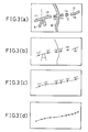
- the operator is to specify the points on the figures displayed on the CRT display 7 which indicate a single connected line piece. Namely, let the figures displayed be those shown in Fig. 3(a), and let the transverse portions of the figures A, B, C, D straddling across the display from left to right be what is intended to be a single connected line piece, with cuts between each of the figures A, B, C, D and ties from what appears as a letter ' A ' adhered to the transverse portion of the figure A and from the vertical portion crossing over the transverse portion of the figure B.
- the rules to be obeyed by the operator in specifying points are as follows:
- Fig. 3(a) the points marked by the crosses with labels (1) - (6) are specified in the order indicated by the labels, which are read out at the step 26. Then at the step 27, connected figures corresponding to each of these specified points are determined.
- a connected figure corresponding to a point is the connected figure which is either containing the point or the nearest to the point.
- the points (1) and (2) correspond to the connected figure A
- the points (3) and (4) correspond to the connected figure B
- the point (5) corresponds to the connected figure C
- the point (6) corresponds to the connected figure D.
- the extraction of these connected figures are carried out by tracing out the boundaries of such figures.
- the region within which the tracing is carried out is specified in advance so as to avoid the unnecessary tracing such as one for the vertical portion of the figure B in this example beyond what is displayed.
- the boundary of the inner hole such as one marked as I in Fig. 3(a), which will be referred hereafter as the interior boundary as opposed to the outer edges of the figures which will be referred hereafter as the exterior boundary, is traced.
- the extracted figure are thinned at the step 28.
- the thinning can be performed by means of the 3 x 3 logical mask processing applied as the boundaries are traced. By tracing the boundaries of the figure once, the figures are thinned by one picture element, and this is continued until the figures are thinned down to unit width. The thinning may be carried out alternatively for the exterior boundaries and for the interior boundaries.
- the result of the thinning of the figures in Fig. 3(a) is shown in Fig. 3(b) where the points with primed labels corresponds to the respective points with unprimed labels in Fig. 3(a).
- the points with primed labels are chosen to be the points on the thinned figures of Fig. 3(b) closest to the specified points in Fig. 3(a).
- the shortest path in the thinned figures joining these points is determined.
- the use of the shortest path here eliminates the erroneous passage such as one between the points (1)′ and (2)′ through the letter ' A ' like portion of the figure A, so that the unique identification of the line piece specified is possible.
- the ties such as the letter ' A ' like portion of the figure A and the vertical portion of the figure B can be removed in this embodiment, provided that the points are specified correctly.
- the figures contain cuts between the two sequential points such as between the points (2)′ and (3)′, (4)′ and (5)′, and (5)′ and (6)′, the end points of the figures containing each of these points are joined together by straight lines as shown in Fig. 3(c), so that the cuts can also be removed in this embodiment.
- the connected line piece shown in Fig. 3(c) obtained at the step 29 is symbolized in the manner of vector symbolization by linear approximation, i.e., the straight lines are fitted to the connected line piece and the connected line piece is represented by the coordinates of the junctions between the straight lines, as shown in Fig. 3(d).
- the result of this symbolization is displayed or the CRT display 7 for inspection by the operator at the step 31.
- the operator can selects the menu 'symbolization cancel' in order to correct the error.
- the step 32 determines whether this is the case. If not, the operation proceeds to the step 34 in which the result of the symbolization is registered in the memory. Otherwise the display of the latest symbolization is deleted and the image displayed previously before the last symbolization is returned to the CRT display 7, so that the operation of the symbolization may be repeated, in which the operator can correct the error found before, until the menu 'symbolization end' is selected.
- the step 35 determines whether the menu 'symbolization end' is selected. If not, the operation of symbolization from the step 26 on is repeated. Otherwise the operation returns to the initial step 21.
- the symbolization of the figure is achieved by specifying few points on figures displayed and extracting the figure intended to be a single connected line piece automatically in accordance with the specified points, and symbolizing the extracted figure automatically, so that the number of the points to be specified by the operator can be reduced considerably and the operation by the operator can be made very simple.
- the cuts or the ties due to blurring or smearing can be removed by following the simple instruction in specifying the points and the correct figure data can be registered automatically.
- the linear approximation used in the above embodiment may be replaced by a curve approximation or by a combination of the linear and curve approximations.
- the interpolation of the figures over the cuts by means of straight lines can be replaced by one by means of curves such as a spline interpolation.
- the image reading by means of the scanner can be replaced by an image reading from a recording device such as an optical disk device of a recorded image.
- the tablet can be replaced by a mouse.
- the specification of the points can be replaced by a tracing of the figures on the display and the sampling of the points at certain timings.
Landscapes
- Engineering & Computer Science (AREA)
- Physics & Mathematics (AREA)
- General Physics & Mathematics (AREA)
- Theoretical Computer Science (AREA)
- Artificial Intelligence (AREA)
- Computer Hardware Design (AREA)
- Computer Vision & Pattern Recognition (AREA)
- Multimedia (AREA)
- Image Processing (AREA)
- Image Analysis (AREA)
- User Interface Of Digital Computer (AREA)
Applications Claiming Priority (2)
| Application Number | Priority Date | Filing Date | Title |
|---|---|---|---|
| JP285903/87 | 1987-11-12 | ||
| JP62285903A JPH01126717A (ja) | 1987-11-12 | 1987-11-12 | 線図形入力装置および線図形入力方法 |
Publications (2)
| Publication Number | Publication Date |
|---|---|
| EP0316003A2 true EP0316003A2 (fr) | 1989-05-17 |
| EP0316003A3 EP0316003A3 (fr) | 1991-03-27 |
Family
ID=17697511
Family Applications (1)
| Application Number | Title | Priority Date | Filing Date |
|---|---|---|---|
| EP19880118830 Withdrawn EP0316003A3 (fr) | 1987-11-12 | 1988-11-11 | Codeur de figures de lignes |
Country Status (3)
| Country | Link |
|---|---|
| US (1) | US5168553A (fr) |
| EP (1) | EP0316003A3 (fr) |
| JP (1) | JPH01126717A (fr) |
Families Citing this family (5)
| Publication number | Priority date | Publication date | Assignee | Title |
|---|---|---|---|---|
| US5694536A (en) * | 1994-02-14 | 1997-12-02 | Digital Equipment Corporation | Method and apparatus for automatic gap closing in computer aided drawing |
| US5574839A (en) * | 1994-02-14 | 1996-11-12 | Digital Equipment Corporation | Method and apparatus for automatic gap closing in computer aided drawing |
| US5521986A (en) * | 1994-11-30 | 1996-05-28 | American Tel-A-Systems, Inc. | Compact data input device |
| US6459779B2 (en) * | 1998-09-04 | 2002-10-01 | Ameritech Corporation | System and method for creating a billing record with a called party's name |
| US6633746B1 (en) * | 1998-11-16 | 2003-10-14 | Sbc Properties, L.P. | Pager with a touch-sensitive display screen and method for transmitting a message therefrom |
Family Cites Families (14)
| Publication number | Priority date | Publication date | Assignee | Title |
|---|---|---|---|---|
| JPS5580188A (en) * | 1978-12-12 | 1980-06-17 | Nippon Telegr & Teleph Corp <Ntt> | Linear pattern coding unit |
| JPS57165836A (en) * | 1981-04-06 | 1982-10-13 | Dainippon Screen Mfg Co Ltd | Method and apparatus for tracing and recording object to be traced |
| JPS58166348A (ja) * | 1982-03-26 | 1983-10-01 | Dainippon Printing Co Ltd | 印刷用切抜きマスク作成装置 |
| JPS58176638A (ja) * | 1982-04-09 | 1983-10-17 | Dainippon Screen Mfg Co Ltd | 抜きマスク版の作製方法 |
| JPS59191667A (ja) * | 1983-04-16 | 1984-10-30 | Dainippon Printing Co Ltd | 画像デ−タ変換方式 |
| JPS6079485A (ja) * | 1983-10-06 | 1985-05-07 | Sharp Corp | 手書き文字認識処理装置 |
| JPS60111490A (ja) * | 1983-11-22 | 1985-06-17 | 富士通株式会社 | プリント板パタ−ン図自動デイジタイズ装置 |
| JPS60217477A (ja) * | 1984-04-12 | 1985-10-31 | Toshiba Corp | 手書き文字認識装置 |
| JPS6165290A (ja) * | 1984-09-07 | 1986-04-03 | 株式会社日立製作所 | ベクトル文字フオントの作成装置 |
| US4807142A (en) * | 1984-10-09 | 1989-02-21 | Wang Laboratories, Inc. | Screen manager multiple viewport for a multi-tasking data processing system |
| US4800510A (en) * | 1985-07-31 | 1989-01-24 | Computer Associates International, Inc. | Method and system for programmed control of computer generated graphics layout |
| US4757549A (en) * | 1985-12-12 | 1988-07-12 | International Business Machines Corp. | Freehand drawing containing invisible lines |
| JPS62269276A (ja) * | 1986-05-19 | 1987-11-21 | Nippon Telegr & Teleph Corp <Ntt> | 会話型図形入力方式 |
| US4847605A (en) * | 1987-04-27 | 1989-07-11 | International Business Machines Corporation | Picking in a graphics system |
-
1987
- 1987-11-12 JP JP62285903A patent/JPH01126717A/ja active Pending
-
1988
- 1988-11-11 EP EP19880118830 patent/EP0316003A3/fr not_active Withdrawn
-
1990
- 1990-10-30 US US07/607,630 patent/US5168553A/en not_active Expired - Fee Related
Also Published As
| Publication number | Publication date |
|---|---|
| JPH01126717A (ja) | 1989-05-18 |
| US5168553A (en) | 1992-12-01 |
| EP0316003A3 (fr) | 1991-03-27 |
Similar Documents
| Publication | Publication Date | Title |
|---|---|---|
| JP2932193B2 (ja) | 図形処理装置 | |
| US5168553A (en) | Line figure encoder | |
| US20020051009A1 (en) | Method and apparatus for extracting object from video image | |
| JP2002373334A (ja) | 指紋特徴抽出装置、指紋特徴抽出方法及び指紋抽出プログラム | |
| US5301264A (en) | Figure encoder | |
| JPS6260674A (ja) | 文書作成装置 | |
| JP2822967B2 (ja) | 簡易地図作成装置 | |
| JPS61253587A (ja) | 光学文字読取装置 | |
| JP2803736B2 (ja) | 文字認識方式 | |
| JP2641249B2 (ja) | シンボル図形配置方法 | |
| JPS63197266A (ja) | 文書イメ−ジ編集装置 | |
| JPH1139366A (ja) | コンピュータ入力システム及び方法 | |
| JP2001282785A (ja) | 文書画像処理装置およびそのための方法、ならびに文書画像処理プログラムを記録したコンピュータで読取可能な記録媒体 | |
| JPH0696272A (ja) | 帳票フォーマット定義体作成装置 | |
| JP3093366B2 (ja) | 画像処理方法及び装置 | |
| JPH10269312A (ja) | 文字読取領域指定方法 | |
| JP4544691B2 (ja) | 文字読取装置 | |
| JPS61198376A (ja) | 光学的文字読取装置 | |
| JPH07117967B2 (ja) | 図面処理システム | |
| JPH10116331A (ja) | 図形の描画処理方法 | |
| JPS63276682A (ja) | 文字読取り装置 | |
| JPH0459669B2 (fr) | ||
| JPH1185904A (ja) | 文字切り出し方法及びこれを用いた文字認識装置 | |
| JP2988697B2 (ja) | 図形認識方式 | |
| JPH06333008A (ja) | 画像輪郭指定用入力装置 |
Legal Events
| Date | Code | Title | Description |
|---|---|---|---|
| PUAI | Public reference made under article 153(3) epc to a published international application that has entered the european phase |
Free format text: ORIGINAL CODE: 0009012 |
|
| 17P | Request for examination filed |
Effective date: 19881111 |
|
| AK | Designated contracting states |
Kind code of ref document: A2 Designated state(s): DE FR GB IT NL |
|
| PUAL | Search report despatched |
Free format text: ORIGINAL CODE: 0009013 |
|
| AK | Designated contracting states |
Kind code of ref document: A3 Designated state(s): DE FR GB IT NL |
|
| 17Q | First examination report despatched |
Effective date: 19930429 |
|
| STAA | Information on the status of an ep patent application or granted ep patent |
Free format text: STATUS: THE APPLICATION IS DEEMED TO BE WITHDRAWN |
|
| 18D | Application deemed to be withdrawn |
Effective date: 19931110 |