EP0316008A2 - Elektrofotografisches Kopiergerät - Google Patents
Elektrofotografisches Kopiergerät Download PDFInfo
- Publication number
- EP0316008A2 EP0316008A2 EP88118837A EP88118837A EP0316008A2 EP 0316008 A2 EP0316008 A2 EP 0316008A2 EP 88118837 A EP88118837 A EP 88118837A EP 88118837 A EP88118837 A EP 88118837A EP 0316008 A2 EP0316008 A2 EP 0316008A2
- Authority
- EP
- European Patent Office
- Prior art keywords
- document
- document platen
- platen
- copying machine
- electrophotographic copying
- Prior art date
- Legal status (The legal status is an assumption and is not a legal conclusion. Google has not performed a legal analysis and makes no representation as to the accuracy of the status listed.)
- Granted
Links
- 230000007246 mechanism Effects 0.000 claims abstract description 29
- 230000033001 locomotion Effects 0.000 claims description 18
- 230000005012 migration Effects 0.000 abstract description 18
- 238000013508 migration Methods 0.000 abstract description 18
- 230000002950 deficient Effects 0.000 abstract 1
- 239000000543 intermediate Substances 0.000 description 35
- 230000033458 reproduction Effects 0.000 description 19
- 108091008695 photoreceptors Proteins 0.000 description 18
- 238000000034 method Methods 0.000 description 6
- 238000012384 transportation and delivery Methods 0.000 description 6
- 230000005611 electricity Effects 0.000 description 4
- 238000012545 processing Methods 0.000 description 4
- 208000034423 Delivery Diseases 0.000 description 3
- 238000010586 diagram Methods 0.000 description 2
- 238000004519 manufacturing process Methods 0.000 description 2
- 230000003287 optical effect Effects 0.000 description 2
- 229910000831 Steel Inorganic materials 0.000 description 1
- 230000004075 alteration Effects 0.000 description 1
- 238000011161 development Methods 0.000 description 1
- 238000007599 discharging Methods 0.000 description 1
- 230000008030 elimination Effects 0.000 description 1
- 238000003379 elimination reaction Methods 0.000 description 1
- 230000000670 limiting effect Effects 0.000 description 1
- 230000004048 modification Effects 0.000 description 1
- 238000012986 modification Methods 0.000 description 1
- 229920000136 polysorbate Polymers 0.000 description 1
- 230000008569 process Effects 0.000 description 1
- 238000004886 process control Methods 0.000 description 1
- 238000005096 rolling process Methods 0.000 description 1
- 239000010959 steel Substances 0.000 description 1
- 238000011144 upstream manufacturing Methods 0.000 description 1
Images




Classifications
-
- G—PHYSICS
- G03—PHOTOGRAPHY; CINEMATOGRAPHY; ANALOGOUS TECHNIQUES USING WAVES OTHER THAN OPTICAL WAVES; ELECTROGRAPHY; HOLOGRAPHY
- G03G—ELECTROGRAPHY; ELECTROPHOTOGRAPHY; MAGNETOGRAPHY
- G03G15/00—Apparatus for electrographic processes using a charge pattern
- G03G15/60—Apparatus which relate to the handling of originals
- G03G15/605—Holders for originals or exposure platens
-
- G—PHYSICS
- G03—PHOTOGRAPHY; CINEMATOGRAPHY; ANALOGOUS TECHNIQUES USING WAVES OTHER THAN OPTICAL WAVES; ELECTROGRAPHY; HOLOGRAPHY
- G03B—APPARATUS OR ARRANGEMENTS FOR TAKING PHOTOGRAPHS OR FOR PROJECTING OR VIEWING THEM; APPARATUS OR ARRANGEMENTS EMPLOYING ANALOGOUS TECHNIQUES USING WAVES OTHER THAN OPTICAL WAVES; ACCESSORIES THEREFOR
- G03B27/00—Photographic printing apparatus
- G03B27/32—Projection printing apparatus, e.g. enlarger, copying camera
- G03B27/52—Details
- G03B27/62—Holders for the original
- G03B27/6207—Holders for the original in copying cameras
- G03B27/6221—Transparent copy platens
- G03B27/6235—Reciprocating copy platens
-
- G—PHYSICS
- G03—PHOTOGRAPHY; CINEMATOGRAPHY; ANALOGOUS TECHNIQUES USING WAVES OTHER THAN OPTICAL WAVES; ELECTROGRAPHY; HOLOGRAPHY
- G03G—ELECTROGRAPHY; ELECTROPHOTOGRAPHY; MAGNETOGRAPHY
- G03G15/00—Apparatus for electrographic processes using a charge pattern
- G03G15/50—Machine control of apparatus for electrographic processes using a charge pattern, e.g. regulating differents parts of the machine, multimode copiers, microprocessor control
Definitions
- the present invention relates to improvements in control of the movement of the document platen in an electrophotographic copying machine of the type in which the document platen is movable with respect to the machine body.
- the moving distance of the document platen varies with the size of a document
- the document platen is moved to a maximum extent at all times regardless of the document size.
- the former method is superior in shortened reproduction time to the latter. Accordingly, it is a general practice to employ the former method.
- the electrophotographic copying machine employing the former method has sometime presented the problem that the slide rail mechanism such as ACCURIDE or the like is not smoothly moved when a larger-size document is reproduced after several reproductions of a smaller-size document have been made.
- the slide rail mechanism such as ACCURIDE has a longitudiinal outer member extending in the moving direction of the document platen, an inner member slidable in the longitudinal direction of the outer member, and an intermediate member inserted between the outer and inner members.
- the intermediate member has spherical bodies for assuring smooth slide of the inner member with respect to the outer member.
- the outer member is attached to the document platen, while the inner member is attached to the machine body. When the document platen is moved, the outer member and the inner member are relatively moved through the intermediate member.
- the document platen is repeatedly subjected to advance at a relative slow expo sure speed and retreat at a relative fast return speed in a predetermined range.
- the intermediate member will fail to follow the movement of the inner and outer members at the time when the movement of the document platen is switched from advance to retreat. This prevents the spherical bodies of the intermediate member from rotating between the outer and inner members, but causes these spherical bodies to slip therebetween. This results in alteration in the positional relationship between the outer member and the intermediate member or between the inner member and the intermediate member. That is, the intermediate member presents migration.
- the intermediate member presenting such migration when intending to reproduce a document having a size larger than that of the document previously reproduced, the intermediate member presenting the migration is returned to the original state where the intermediate member presents no migration, with the movement of the outer member when the document platen is moved in the exposure direction exceeding the previous small-size document area.
- This generates sliding friction between the outer member and the spherical bodies of the intermediate member or between the inner member and the spherical bodies of the intermediate member.
- This applies a load to the document platen under exposure, causing exposure deviation, i.e., deviation of a reproduced image from the image to be reproduced.
- the reproduced image is impossible to read, or illegible.
- the document platen and the machine body are connected by a slide rail mechanism having an outer member, an inner member and an intermediate mamber which are slidably combined with one another, and the document platen is adapted to be moved, in principle, by a distance corresponding to the size of a document mounted on the machine.
- the machine in accordance with the present invention is characterized by movement control means adapted to move the document platen to a maximum extent regardless of the size of the document, at the time of the last reproducing operation in a series of reproducing operations.
- the document platen is moved to a maximum extent at the time of the last reproducing operation in a series of reproducing operations, even though the slide rail mechanism presents migration due to a plurality of serial reproductions made from a relatively small sized document.
- the intermediate member presenting the migration is returned to the original state where the intermediate member presents no migration, thus eliminating the migration of the slide rail mechanism.
- the sliding of the intermediate member causes a somewhat excessive load to be applied to the document platen under movement.
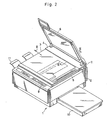
- Fig. 2 is a perspective view illustrating the appearance of an electrophotographic copying machine in accordance with an embodiment of the present invention.
- the electrophotographic copying machine 1 is provided on the body 2 thereof with a document platen 3.
- the document platen 3 is provided with a transparent platen 5 attached to a transparent platen mounting portion 4, and a cover 6 for covering the transparent platen 5.
- the entire document platen 3 is attached to the top surface of the machine body 2 through a slide rail 7.
- the slide rail 7 is adapted to move the document platen 3 transversely with respect to the machine body 2, i.e., in the direction shown by an arrow 8.
- slide rail 7 includes the slide rail "ACCURIDE (registered trademark)" manufactured by Japan Accuride Co., Ltd.
- the machine body 2 is 'provided at the upper front portion thereof with an operation panel 9 having a variety of operation buttons and display units.
- the machine body 2 is so arranged that a cassette 10 housing copy paper may be inserted into the lower portion of the right lateral side of the machine body 2 and that a discharge tray 11 for receiving copy paper on which image reproduction has been made, may be attached to the left lateral side of the machine body 2.
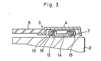
- Fig. 3 is an end view of a portion taken along the line III-III in Fig. 2.
- the slide rail 7 includes an inner member 12 attached to the top surface of the machine body 2, an outer member 13 attached to the underside of the transparent platen mounting portion 4 and an intermediate member 14 between the inner member 12 and the outer member 13.
- the intermediate member 14 rotatingly holds spherical bodies 15 such as steel balls or the like which come in contact with both inner and outer members 12 and 13.
- the document platen 3 including the outer member 13 may be slided transversely with respect to the machine body 2 including the inner member 12 (in a direction at right angle to the paper plane in Fig. 3).
- this sliding operation only a rolling friction due to the spherical bodies 15 is present between the document platen 3 and the machine body 2. This enables the document platen 3 to be slided very smoothly with respect to the machine body 2.
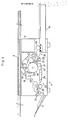
- Fig. 4 is a view in front elevation of the electrophotographic copying machine 1.
- the document platen 3 as transversely moved with the cover closed is shown by two dot chain lines, and the inner arrangement of the electrophotographic copying machine 1 is schematically shown.
- the machine body 2 incorporates an optical system including an exposure lamp 16 for exposing a document and a focusing lens 17 for focusing the light reflected from the document.
- the optical system is opposite to the movable document platen 3.
- a photoreceptor drum 18 is also disposed for forming an electrostatic latent image based on the light focused by the focusing lens 17. Disposed around the photoreceptor drum 18 are a corona discharger 19, a developing device 20, a transferring corona discharger 21, a separating corona discharger 22 and a cleaner 23.
- the corona discharger 19 is disposed for uniformly charging, with electricity, the photoreceptor layer on the surface of the photoreceptor drum 18.
- an electrostatic latent image is formed according to the irradiated light.
- the developing device 20 is disposed for developing the electrostatic latent image with toner adsorbed on the surface of the photoreceptor drum 18.
- the transferring corona discharger 21 is disposed for transferring a toner image formed on the surface of the photoreceptor drum 18, to copy paper.
- the separating corona discharger 21 is disposed for separating the copy paper on which the toner image has been transferred, from the surface of the photoreceptor drum 18.
- the cleaner 23 is disposed for collecting the toner remaining on the surface of the photoreceptor drum 18.
- the electrophotographic copying machine 1 is also provided with a paper feed mechanism 24 for delivering copy paper in association with the rotation of the photoreceptor drum 18, and a delivery/fixing mechanism 25.
- the paper feed mechanism 24 includes a paper feed roller 26 for taking out copy paper from the cassette 10, and a pair of resist rollers 27 for feeding copy peper to the photoreceptor drum 18 in good timing. Disposed immediately upstream of the resist rollers 27 is a resist switch 28 for making sure of the presence of copy paper to be fed.
- the resist switch 28 is adapted to be turned ON and OFF, respectively, when the tip and rear end of copy paper fed is detected.
- the delivery/fixing mechanism 25 includes a delivery belt 29 for delivering the copy paper onto which a toner image has been transferred, a fixing device 30 for fixing the transferred toner image, and a pair of discharge rollers 31 for discharging the copy paper on which the toner image has been fixed, to the discharge tray 11.
- the photoreceptor drum 18 is rotated clockwise in Fig. 4. In association with this rotation, the document platen 3 is moved for exposure.
- the paper feed mechanism 24 starts paper feeding.
- the light reflected from the document is applied to the surface of the photoreceptor drum 18 which has been uniformly charged with electricity by the corona discharger 19, an electrostatic latent image of the document is formed.
- the developing device 20 gives toner to the electrostatic latent image thus formed, which is then developed.
- the resist rollers 27 starts paper feeding.
- the copy paper sticks to the surface of the photoreceptor drum 18 on which the electrostatic latent image has been developed, and the toner image is then transferred to the copy paper by the transferring corona discharger 21.
- This copy paper is separated from the surface of the photoreceptor drum 18 by the separating corona discharger 22.
- the copy paper is then sent to the delivery/fixing mechanism 25, in which the toner image is fixed by the fixing device 30.
- the copy paper is discharged to the discharge tray 11 by the discharge rollers 31.
- the surface of the photoreceptor drum 18 from which the copy paper has been separated, is cleaned by the cleaner 23.
- the surface of the photoreceptor drum 18 is again charged with electricity by the corona discharger 19.
- Fig. 5 is a plan view schematically illustrating the position detector mechanism of the document platen 3.
- the position detector mechanism has a pair of position detector switches 32a, 32b disposed, for example, on the top surface of the machine body, and projections 33 to 37 formed at predetermined positions under the document platen 3.
- the projection 33 pushes the position detector switch 32a.
- the projection 34 pushes the position detector switch 32b.
- the projection 35 pushes the position detector switch 32a such that the tip of the document is recognized.
- the actuator projections 36 and 37 push the position detector switches 32a and 32b, respectively. This enables to detect the position of the document platen 3 based on outputs from the position detector switches 32a, 32b.
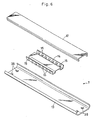
- Fig. 6 is a perspective exploded view of the slide rail 7.
- the slide rail 7 is shown with upside down, as compared with the arrangement in which the slide rail 7 is actually mounted on the electrophotographic copying machine as shown in Fig. 3.
- Each of the inner member 12 and the outer member 13 of the slide rail 7 is a longitudinal member having a substantially C-shape section. These members 12 and 13 are assembled such that the respective C-shape open surfaces are opposite to each other.
- the inner member 12 and the outer member 13 have the substantially same length.
- the intermediate member 14 has a length about half of that of the inner and outer members 12 and 13.
- Each of the turned lateral sides at both ends in the widthwise direction rotatably holds a plurality of spherical bodies 15 (seven spherical bodies in Fig. 6).
- the outer member 13 is provided in the vicinity of the tip and rear ends thereof with projections 38 for limiting the movement of the intermediate member 14.
- the slide rail 7 is formed by combining the inner member 12, the outer member 13 and the intermediate member 14 as shown in Fig. 3.
- the slide rail 7 is adapted to slide with the predetermined positional relationship among these three members maintained.
- Fig. 7 illustrates the document platen 3 as moved to different positions for image reproduction, and the positional relationship among the inner member 12, the outer member 13 and the intermediate member 14 of the slide rail 7 at each of the positions of the document platen 3.
- Fig. 7 (A) to (D) show the positions of the document platen 3, while (a) to (d) respectively show the positions of the slide rail located in association with the movement of the document platen 3 to the positions (A) to (D).
- the movement of the document platen 3 is controlled in the following manner.
- Fig. 8 is a schematic block diagram of the control unit of the electrophotographic copying machine 1, illustrating only the members necessary for control operation in accordance with the feature of this embodiment.
- the control processing is executed by a microcomputer 39.
- the microcomputer 39 includes a memory 40 in which necessary operational programs and data have been previously stored or are to be stored as necessary. Signals from the resist switch 28 and the position detector switches 32a, 32b are given to the microcomputer 39.
- the microcomputer 39 executes a control processing based on the signals thus entered and the operational programs, thereby to control the expo sure lamp 16, a drive motor 41, the document platen 3 and the paper feed mechanism 24.
- Fig. 1 is a flowchart of the control operations of the microcomputer 39 in Fig. 8.
- the microcomputer 39 drives the drive motor 41, enabling the document platen 3 and the paper feed mechanism 24 to be operable (Step S1). Then, an operation start signal is given to the paper feed mechanism 24, which in turn starts paper feeding (Step S2), and the document platen 3 starts moving toward the exposure start position (Step S3).
- Step S4 When the resist switch 28 (See Fig. 4) is turned ON by the tip end of copy paper thus fed, it is judged that paper feeding is completed (Step S4).
- the position detector switch 32b When the position detector switch 32b is pushed and turned ON by the projection 34 of the document platen 3 (See Fig. 5), it is judged that the document platen 3 has arrived at the exposure start position (Step S5).
- the microcomputer 39 causes the document platen 3 to be moved in the exposure direction (Step S6).
- the position detector switch 32a is turned ON by the projection 35 of the document platen 3 to determine the feeding timing of the tip of the copy paper (Step S7).
- the copy paper fed by the pair of resist rollers 27 of the paper feed mechanism 24 is delivered to the photoreceptor drum 18, and the next paper feeding starts (Step S8).
- a reproduction process control known per se is executed (Step S9).
- Step S10 When the pair of resist rollers 27 feed the copy paper and the rear end of the copy paper is delivered, the resist switch 28 is turned OFF. By the resist switch OFF signal, the microcomputer 39 recognizes the rear end of the fed copy paper (Step S10), and then judges whether or not the number of copies previously set in the memory 40 has reached 0 (Step S11).
- Step S12 the microcomputer 39 immediately stops the document platen 3 (Step S12) and executes again the processings above-mentioned from Step S2. Accordingly, the document platen 3 of the electrophotographic copying machine 1 is returned to the exposure start position for the next reproduction, immediately after moved for exposure by a distance corresponding to the document size. This enables to shorten the reproduction time required for a plurality of reproductions.
- Step S13 when the microcomputer 39 judges at the step S11 that the remaining number of copies to be made is zero, the microcomputer 39 causes the document platen 3 to be continuously moved, and it is waited until the document platen 3 is moved to a maximum extent in the exposure direction (Step S13).
- the document platen 3 is moved to a maximum extent in the exposure direction. Accordingly, even though the intermediate member 14 exhibits migration as shown in Fig. 7 (d), the outer member 13 is moved to the right-hand maximum moving position, thus eliminating the migration of the intermediate member 14.
- the position detector switches 32a and 32b are turned ON by the projections 36 and 37 of the document platen 3. Accordingly, the microcomputer 39 stops the document platen 3 (Steps S13 and S14) based on the ON signals of the position detector switches 32a, 32b. This causes the document platen 3 to start moving in the return direction (Step S15).
- Step S16 When the position detector switch 32a is turned ON by the actuator projection 33 of the document platen 3, it is judged that the document platen 3 has reached the home position (Step S16). This causes the document platen 3 to be stopped (Step S17) and also causes the drive motor 41 to be stopped (Step S18).
- the document platen 3 when the remain ing number of copies in a plurality of reproductions to be made, is not "0" as shown at Steps S11 and S12, the document platen 3 is stopped and moved in the return direction immediately after completion of document exposure.
- the document platen 3 may be moved, as it is, in the exposure direction even after completion of document exposure.
- the document platen 3 when the document platen 3 has reached, for example, the home position, the document platen 3 may be stopped and then moved in the return direction. This is because there may be the following problems if the document platen 3 is stopped and moved in the return direction immediately after completion of document exposure when exposing the document having an extremely small size.
- the slide rail mechanism repeats reciprocation with mincing steps corresponding to the small-size document.
- the relationship among the inner, outer and intermediate members is altered due to each backlash present between the intermediate member and the inner member and between the intermediate member and the outer member.
- the problems above-mentioned may be overcome by moving the document platen 3 by a relatively long distance to increase the distance of reciprocating movement of the respective members even when exposing a small- size document.
- the document platen is moved to a maximum extent regardless of the document size at the time of the last reproducing operation in a series of reproducing operations.
- the migration can be eliminated by the arrangement that the document platen is continuously moved up to the maximum moving position even after completion of the last exposure. This does not produce a failure in the subsequent reproduction.
- the present invention can be embodied with the use of a simple software processing. This requires no modification in mechanism of a conventional electrophotographic copying machine. Thus, the present invention may be embodied economically.
Landscapes
- Physics & Mathematics (AREA)
- General Physics & Mathematics (AREA)
- Engineering & Computer Science (AREA)
- Microelectronics & Electronic Packaging (AREA)
- Optical Systems Of Projection Type Copiers (AREA)
- Holders For Sensitive Materials And Originals (AREA)
- Exposure Or Original Feeding In Electrophotography (AREA)
- Facsimile Scanning Arrangements (AREA)
Applications Claiming Priority (2)
| Application Number | Priority Date | Filing Date | Title |
|---|---|---|---|
| JP286703/87 | 1987-11-12 | ||
| JP62286703A JPH0648346B2 (ja) | 1987-11-12 | 1987-11-12 | 電子写真複写機 |
Publications (3)
| Publication Number | Publication Date |
|---|---|
| EP0316008A2 true EP0316008A2 (de) | 1989-05-17 |
| EP0316008A3 EP0316008A3 (en) | 1990-07-25 |
| EP0316008B1 EP0316008B1 (de) | 1993-09-08 |
Family
ID=17707896
Family Applications (1)
| Application Number | Title | Priority Date | Filing Date |
|---|---|---|---|
| EP88118837A Expired - Lifetime EP0316008B1 (de) | 1987-11-12 | 1988-11-11 | Elektrofotografisches Kopiergerät |
Country Status (4)
| Country | Link |
|---|---|
| US (1) | US4969014A (de) |
| EP (1) | EP0316008B1 (de) |
| JP (1) | JPH0648346B2 (de) |
| DE (1) | DE3883920T2 (de) |
Family Cites Families (10)
| Publication number | Priority date | Publication date | Assignee | Title |
|---|---|---|---|---|
| JPS4912184B1 (de) * | 1969-04-25 | 1974-03-22 | ||
| JPS5837065Y2 (ja) * | 1975-11-18 | 1983-08-20 | シャープ株式会社 | 複写機における原稿台 |
| JPS601613B2 (ja) * | 1978-07-31 | 1985-01-16 | コニカ株式会社 | 電子写真複写装置 |
| JPS5614258A (en) * | 1979-07-16 | 1981-02-12 | Canon Inc | Image forming device |
| JPS6131540Y2 (de) * | 1980-08-27 | 1986-09-13 | ||
| JPS58154859A (ja) * | 1982-03-11 | 1983-09-14 | Fuji Xerox Co Ltd | 複写機 |
| JPS59188630A (ja) * | 1983-04-12 | 1984-10-26 | Mita Ind Co Ltd | 静電複写機 |
| JPS6051839A (ja) * | 1983-08-31 | 1985-03-23 | Toshiba Corp | 画像形成装置 |
| JPH0711672B2 (ja) * | 1984-08-06 | 1995-02-08 | 三洋電機株式会社 | 原稿露光走査装置 |
| JPS6391649A (ja) * | 1986-10-04 | 1988-04-22 | Sharp Corp | 原稿台移動型複写機のスライド装置 |
-
1987
- 1987-11-12 JP JP62286703A patent/JPH0648346B2/ja not_active Expired - Lifetime
-
1988
- 1988-11-07 US US07/267,556 patent/US4969014A/en not_active Expired - Lifetime
- 1988-11-11 EP EP88118837A patent/EP0316008B1/de not_active Expired - Lifetime
- 1988-11-11 DE DE88118837T patent/DE3883920T2/de not_active Expired - Fee Related
Also Published As
| Publication number | Publication date |
|---|---|
| DE3883920T2 (de) | 1994-01-27 |
| DE3883920D1 (de) | 1993-10-14 |
| EP0316008A3 (en) | 1990-07-25 |
| US4969014A (en) | 1990-11-06 |
| JPH0648346B2 (ja) | 1994-06-22 |
| JPH01128076A (ja) | 1989-05-19 |
| EP0316008B1 (de) | 1993-09-08 |
Similar Documents
| Publication | Publication Date | Title |
|---|---|---|
| US4792828A (en) | Image forming apparatus for forming a plurality of image from different originals on one transfer sheet | |
| US4778170A (en) | Copy sheet tray with adjustable back stop and scuffer mechanism | |
| CA1078450A (en) | Variable edge fadeout apparatus for electrostatic reproduction machines | |
| JP2839504B2 (ja) | 自動原稿送り装置 | |
| US4294535A (en) | Electrostatic copying apparatus | |
| US4046467A (en) | Zoom lens copier | |
| US4645328A (en) | Apparatus for scanning an original | |
| EP0316008A2 (de) | Elektrofotografisches Kopiergerät | |
| US4564288A (en) | Electrostatic recording apparatus | |
| US5016051A (en) | Electrophotographic copying machine with device for shifting an image | |
| US4947217A (en) | Image forming apparatus with control mechanism to correct any abberation in stopping position of original document | |
| US4919409A (en) | Sheet handling apparatus with narrow belt having raised frictional contact element | |
| JPH0713774B2 (ja) | タブ付き複写用紙を扱える複写機 | |
| JPH1063109A (ja) | 画像形成装置 | |
| US4666286A (en) | Apparatus for scanning an original | |
| CA1235730A (en) | Optical system for scanning and flash exposing of document | |
| US4888615A (en) | Image forming apparatus for selective copying of segmented areas of an image | |
| CA1235729A (en) | Document scanning drum and flash exposure copier | |
| JPH01104526A (ja) | 再給紙手段付作像装置 | |
| JPS6129864A (ja) | 可変倍電子写真複写機 | |
| JP3122593B2 (ja) | 原稿搬送装置を備えた画像形成装置 | |
| JP2668157B2 (ja) | 循環式原稿供給装置における原稿給紙方法 | |
| JPH04309969A (ja) | 電子写真装置 | |
| JP3716642B2 (ja) | 画像形成装置の紙搬送方法及び画像形成装置 | |
| JPH10105319A (ja) | 表示装置、およびこの表示装置を備えた画像形成装置 |
Legal Events
| Date | Code | Title | Description |
|---|---|---|---|
| PUAI | Public reference made under article 153(3) epc to a published international application that has entered the european phase |
Free format text: ORIGINAL CODE: 0009012 |
|
| AK | Designated contracting states |
Kind code of ref document: A2 Designated state(s): DE FR GB NL |
|
| PUAL | Search report despatched |
Free format text: ORIGINAL CODE: 0009013 |
|
| AK | Designated contracting states |
Kind code of ref document: A3 Designated state(s): DE FR GB NL |
|
| 17P | Request for examination filed |
Effective date: 19901119 |
|
| 17Q | First examination report despatched |
Effective date: 19920313 |
|
| GRAA | (expected) grant |
Free format text: ORIGINAL CODE: 0009210 |
|
| AK | Designated contracting states |
Kind code of ref document: B1 Designated state(s): DE FR GB NL |
|
| REF | Corresponds to: |
Ref document number: 3883920 Country of ref document: DE Date of ref document: 19931014 |
|
| ET | Fr: translation filed | ||
| PLBE | No opposition filed within time limit |
Free format text: ORIGINAL CODE: 0009261 |
|
| STAA | Information on the status of an ep patent application or granted ep patent |
Free format text: STATUS: NO OPPOSITION FILED WITHIN TIME LIMIT |
|
| 26N | No opposition filed | ||
| PGFP | Annual fee paid to national office [announced via postgrant information from national office to epo] |
Ref country code: GB Payment date: 19941101 Year of fee payment: 7 |
|
| PGFP | Annual fee paid to national office [announced via postgrant information from national office to epo] |
Ref country code: FR Payment date: 19941109 Year of fee payment: 7 |
|
| PGFP | Annual fee paid to national office [announced via postgrant information from national office to epo] |
Ref country code: DE Payment date: 19941110 Year of fee payment: 7 |
|
| PGFP | Annual fee paid to national office [announced via postgrant information from national office to epo] |
Ref country code: NL Payment date: 19941130 Year of fee payment: 7 |
|
| PG25 | Lapsed in a contracting state [announced via postgrant information from national office to epo] |
Ref country code: GB Effective date: 19951111 |
|
| PG25 | Lapsed in a contracting state [announced via postgrant information from national office to epo] |
Ref country code: NL Effective date: 19960601 |
|
| GBPC | Gb: european patent ceased through non-payment of renewal fee |
Effective date: 19951111 |
|
| PG25 | Lapsed in a contracting state [announced via postgrant information from national office to epo] |
Ref country code: FR Effective date: 19960731 |
|
| NLV4 | Nl: lapsed or anulled due to non-payment of the annual fee |
Effective date: 19960601 |
|
| PG25 | Lapsed in a contracting state [announced via postgrant information from national office to epo] |
Ref country code: DE Effective date: 19960801 |
|
| REG | Reference to a national code |
Ref country code: FR Ref legal event code: ST |