EP0316178A2 - Bandkassette - Google Patents
Bandkassette Download PDFInfo
- Publication number
- EP0316178A2 EP0316178A2 EP88310607A EP88310607A EP0316178A2 EP 0316178 A2 EP0316178 A2 EP 0316178A2 EP 88310607 A EP88310607 A EP 88310607A EP 88310607 A EP88310607 A EP 88310607A EP 0316178 A2 EP0316178 A2 EP 0316178A2
- Authority
- EP
- European Patent Office
- Prior art keywords
- cassette
- side walls
- light receiving
- tape
- receiving window
- Prior art date
- Legal status (The legal status is an assumption and is not a legal conclusion. Google has not performed a legal analysis and makes no representation as to the accuracy of the status listed.)
- Granted
Links
Images


Classifications
-
- G—PHYSICS
- G11—INFORMATION STORAGE
- G11B—INFORMATION STORAGE BASED ON RELATIVE MOVEMENT BETWEEN RECORD CARRIER AND TRANSDUCER
- G11B23/00—Record carriers not specific to the method of recording or reproducing; Accessories, e.g. containers, specially adapted for co-operation with the recording or reproducing apparatus ; Intermediate mediums; Apparatus or processes specially adapted for their manufacture
- G11B23/02—Containers; Storing means both adapted to cooperate with the recording or reproducing means
- G11B23/04—Magazines; Cassettes for webs or filaments
- G11B23/08—Magazines; Cassettes for webs or filaments for housing webs or filaments having two distinct ends
- G11B23/087—Magazines; Cassettes for webs or filaments for housing webs or filaments having two distinct ends using two different reels or cores
- G11B23/08707—Details
- G11B23/08714—Auxiliary features
-
- G—PHYSICS
- G11—INFORMATION STORAGE
- G11B—INFORMATION STORAGE BASED ON RELATIVE MOVEMENT BETWEEN RECORD CARRIER AND TRANSDUCER
- G11B23/00—Record carriers not specific to the method of recording or reproducing; Accessories, e.g. containers, specially adapted for co-operation with the recording or reproducing apparatus ; Intermediate mediums; Apparatus or processes specially adapted for their manufacture
- G11B23/02—Containers; Storing means both adapted to cooperate with the recording or reproducing means
- G11B23/04—Magazines; Cassettes for webs or filaments
- G11B23/08—Magazines; Cassettes for webs or filaments for housing webs or filaments having two distinct ends
- G11B23/087—Magazines; Cassettes for webs or filaments for housing webs or filaments having two distinct ends using two different reels or cores
- G11B23/08707—Details
- G11B23/08735—Covers
Definitions
- This invention relates to a tape cassette suitable for use in recording and reproducing video and audio signals on an 8-mm video and the like.
- one end of pieces of transparent leader tape and trialer tape are respectively fixed to the supply and take-up reels provided in parallel within the cassette, and a magnetic tape is connected between the leader tape and the trailer tape and wound on the supply reel or take-up reel.
- the ends of the magnetic tape are detected by the detection of the transmitted light or reflected light from the transparent leader tape and trailer tape.
- a cassette particularly for use in recording and reproducing a video signal and in which the transmitted light is used for the detection of the ends of magnetic tape is disclosed in Japanese Utility Model Laid-Open Gazette No. 40618/1980.
- a light projector insertion aperture is provided in the bottom of the cassette near the front between the supply reel and the take-up reel within the cassette, and a light receiving and passing window hole for allowing the passage of the light from the light emitting elements inserted in the projector insertion hole, is provided in both side walls of this cassette.
- the leader tape or trailer overlies the light receiving window holes, the light from the light emitting element is passed to a light receiving element provided outside the cassette near the light receiving window hole and when the magnetic tape itself is opposite the light receiving window holes, the light emanating from the light emitting element is cut off. Therefore, the ends of the magnetic tape can be detected by these means.
- the above-mentioned prior art tape cassette structure has the drawback that when the casette uses a metal tape, particularly of binderless metal type and such a film is stored for a long time, dust, powdery dust, corrosive gases contained in the air and so on enter into the cassette through the light receiving window apertures in both sides of the cassette and the projector insertion hole so as to contact the magnetic tape surface and particularly to corrode the evaporated film side of the tape, causing rust thereon.
- this invention is to provide a tape cassette that is improved in its air-tightness in order that powdery dust, dirt and corrosive gases contained in the air can be prevented from entering the cassette, thus solving the problems of rust, dropout and clogging of magnetic heads.
- a tape cassette 10 having a projector insertion hole 6 provided in a bottom 5 of a cassette 1 to be near the cassette front between a supply reel 2a and a take-up reel 2b enclosed within the cassette, light receiving window holes 8a, 8b provided in both side walls of the cassette 1 to allow the light from a light emitting element inserted in the projector insertion hole 6 to be passed therethrough, and an opening/closing lid pivotably mounted through arms 16a,16b on the front side of the cassette 1 so that in a non-used condition, the light receiving window holes 8a, 8b are closed by the lid, and, further as in the embodiment shown in FIG.
- ribs 20 are provided on the cassette wall in the vicinity of the light receiving window holes 8a,8b provided in both the side walls 7a,7b of the cassette 1, or are provided on the inside surfaces of the arms 161,16b of the opening/closing lid 9 near such positions as to baffle or block the light receiving window holes 8a,8b in both the side walls 7a,7b, preventing dust from entering the cassette.
- baffle ribs are provided near the light receiving window holes 8a,8b, preventing gases or dust from entering the cassette, and improving the air-tightness of the cassette so that the magnetic tape can be prevented from rusting.
- This invention proposes a tape cassette suitable for use in recording and reproducing video and audio signals on an 8-mm video tape recorder or the like, and which has a light projector insertion aperture provided in the bottom of the cassette to be near the cassette front between the supply and take-up reels enclosed within the cassette.
- Light receiving and passing window apertures are provided in both side walls of the cassette to allow the light from the light emitting element inserted in the projector insertion aperture to pass therethrough.
- An opening/closing lid is mounted through integral arms over the front side of the cassette so that in a non-used condition, the light receiving window holes are closed by the arms of the lid, characterized in that ribs, or baffles, are provided on the cassette side walls in the vicinity of the light receiving window holes provided in both side walls of the cassette, and/or are provided on the insides of the arms of the opening/closing lid near such aperture positions as to block the light receiving window holes in both the side walls, thus preventing dust and gases from entering the cassette so as to thereby protect the magnetic tape in the cassette from rusting.
- FIGS 1 to 5 An embodiment of this invention, or a tape cassette for 8-mm video tape recorder according to this invention will be described with reference to FIGS 1 to 5.
- a cassette 1 that is formed of an upper half 3a and a lower half 3b both made of a synthetic resin material, these upper halves 3a and 3b being combined by mutual engagement into a unitary body.
- the reels 2a and 2b have flanges 13a and 13b formed on the lower side4 on which a magnetic tape 14 is wound.
- One end of a leader tape is fixed to the supply reel 2a and the other end of this leader tape is joined to the start end of the magnetic tape l4.
- leader tape and trailer tape portions are transparent.
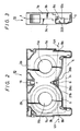
- the leader tape length is so selected that when all the magnetic tape 14 is completely sound on the tape-up reel 2b, the leader tape will face to, or extend across, a light receiving window hole 8a formed in a side wall 7a as shown in FIG. 2.
- the trailer tape length is so selected that when all the magnetic tape 14 is completely wound on the supply reel 2a, the trailer tape will face to or extend across a light receiving window hole 8b formed in a side wall 7b as shown in FIG. 2.
- reel holes 11a and 11b into which the reel drive shafts are to be inserted to drive the supply and take-up reels 2a and 2b.
- a light projector insertion hole 6 is formed therein in which a light emitting element is inserted, and an operation hole 15 in which a reel lock means is inserted from the outside is also formed in the bottom.
- the operation hole 15 is substantially completely closed by the reel lock means and the reel holes 11a and 11b are respectively closed by the supply reel 2a and the takeup reel 2b when the tape cassette is not being used.
- the projector insertion hole 6 is provided with the light emittting element only during recording and reproducing and thus when the tape cassette is not used and is stored, dust may enter the tape cassette through this projector insertion hole 6. Under the condition that the upper half 3a and the lower half 3b are mutually engaged into a set, the portion of the tape cassette in which the magnetic tape 14 is wound on the reels 2a, 2b is substantially closed except for the above-mentioned projector insertion hole 6, the light receiving window holes 8a, 8b and the opening 4 across which the magnetic tape is extended.
- the magnetic tape extended across the opening 4 is exposed upon recording and reproducing as shown in FIG. 2, but when the tape cassette is not used and is stored, the magnetic tape is covered by the opening/closing lid 9 and the sub-lid provided on the back side of the lid 9, and the opening is substantially completely closed as shown in FIG. 4.
- the opening/closing lid 9 and the sub-lid provided on the back side of the lid 9, and the opning is substantially completely closed as shown in FIG. 4.
- the opening/clos9ng lid 9 is constructed so that projections 18 as pivots are formed to extend inward from the left and right arms 161, 16b of the opening/closing lid 9 and to be rotatably engaged in the bearings 12a,12b which are formed in the front portions of the side walls 7a, 7b (sees FIGS. 3 and 5) of the upper and lower halves 3a,3b.
- opening and closing lid light receiving window holes l7a, 17b of, for example, a rectangular shape are formed in the arms 16a, 16b at such positions that when the opening/closing lid 9 is rotated up about the projections 18 as pivots in the arrow-A direction in FIG.
- FIG. 5 partially partially shows the side wall 7a of the cassette 1 and the opening/closing lid 9 to be pivotally mounted on that side wall.
- the light receiving window holes 8a, 8b formed in the side walls 7a, 7b are not aligned with the opening/closing lid light receiving window holes 17a, 17b when the opening/closing lid light receiving window holes 17a, 17b when the opening/closing lid 9 is closed.
- inverted U-letter shaped recesses 21 formed in the lower edges of the side walls of the upper half 3a are combined with parts of the upper edges of the side walls of the lower half 3b to form the bearing holes 12a, 12b.
- inverted L-shaped stair portions formed on the lower edges of the side walls of the upper half near the inverted U-letter shaped recesses 21 are combined with substantially C-letter shaped grooves 23 formed on the upper edges of the side walls 7a, 7b of the lower half 3b to form the light receiving window holes 8a, 8b.
- dust and corrosive gases would enter into the cassette 1 through the window holes 8a, 8b and fall on the magnetic surface of metal tape, causing rust thereon. It has been found that dust and gases entered through the gaps between the arm 16a of the opening/closing lid 9 and the side walls 7a, 7b as indicated by the arrows-D and -E in FIG. 5.
- ribs 20a, 20b are provided on the inner sides of the arms 16a, 16b of the opening/closing lid 9 as shown in FIG. 5, closing the gaps between the cassette 1 and the arms 16a, 16b of the opening/closing lid 9 to cut off air entering in the arrow-D and E direction.
- the ribs 20a, 20b can be provided at such positions 8a′, 8b′, of the light receiving window holes indicated by broken line on the arm 16a). These ribs can thus prevent dust from entering in the arrow-D, E direction.
- FIG. 1 shows another embodiment of this invention wherein ribs 20 are provided on the side walls 7a, 7b of the cassette.
- the ribs 20 are provided only in the vertical direction on the side walls 7a, 7b but ribs 20′ are not provided at positions indicated by the broken line.
- stop projections for locking the lid although not shown, are provided on the inner side of the fore end of the arm 16a of the opening/closing lid 9 and would touch the rib when the lid 9 is opened.
- Such rib 20′ can be replaced by the rib 20b (see FIG. 5) provided on the inner side of the arm 16a of the lid 9.
- windows 26a, 26b are provided on the inner side of the fore end of the arm 16a of the opening/closing lid 9 and would touch the rib when the lid 9 is opened.
- Such rib 20′ can be replaced by the rib 20b (see FIG. 5) provided on the inner side of the arm 16a of the lid 9. Therefore, it is possible to provide vertical ribs on the side walls 7a, 7b and lateral ribs 20′ on the inner sides of the arms 16a, 16n of the lid 9 and thereby to shut off the air entering in the arrow-D E direction.
- windows 26a, 26b (see FIG. 2) for allowing light to pass are provided at the projector insertion hole 6, the windows 26a, 26b are necessary to be closed with a transparent material for preventing dust and gases of the air from entering therethrough.
- the tape cassette 10 constructed as above and the conventional one in which the ordinary ribs 20, 20a, 20b are not provided near the light receiving window holes 8a, 8b were tested to determine how they cause rust after a heat cycle test and long time storage.
- the result was that the tape cassette of the ivnentive embodiments caused no rust near the light receiving window holes, whereas the conventional one with no ribs caused rust.
- the tape cassette of the ivnentive embodiments caused no rust near the light receiving window holes, whereas the conventional one with no ribs caused rust.
- generation of rust can be prevented by providing the described ribs near the light receiving window holes 8a, 8b, no dropout is caused and the magnetic heads are not clogged while the magnetic tape is being passed around the drum.
- This invention is not limited to the above embodiments. but can take various different modifications without departing from the gist of this invention.
- the air-tightness of the cassette 1 in which a magnetic tape is placed can be enhanced by providing the ribs 20,20a, 20b near the light receiving window holes 8a, 8b with the result that dust and gases can be prevented from entering the cassette and that the magnetic tape can be prevented from rusting on its surface.
Landscapes
- Packaging Of Annular Or Rod-Shaped Articles, Wearing Apparel, Cassettes, Or The Like (AREA)
Applications Claiming Priority (2)
| Application Number | Priority Date | Filing Date | Title |
|---|---|---|---|
| JP62284475A JP2600215B2 (ja) | 1987-11-11 | 1987-11-11 | テープカセット |
| JP284475/87 | 1987-11-11 |
Publications (3)
| Publication Number | Publication Date |
|---|---|
| EP0316178A2 true EP0316178A2 (de) | 1989-05-17 |
| EP0316178A3 EP0316178A3 (en) | 1990-03-07 |
| EP0316178B1 EP0316178B1 (de) | 1994-01-12 |
Family
ID=17679004
Family Applications (1)
| Application Number | Title | Priority Date | Filing Date |
|---|---|---|---|
| EP88310607A Expired - Lifetime EP0316178B1 (de) | 1987-11-11 | 1988-11-10 | Bandkassette |
Country Status (6)
| Country | Link |
|---|---|
| US (1) | US4984122A (de) |
| EP (1) | EP0316178B1 (de) |
| JP (1) | JP2600215B2 (de) |
| KR (1) | KR0135086B1 (de) |
| CA (1) | CA1314034C (de) |
| DE (1) | DE3887092T2 (de) |
Cited By (3)
| Publication number | Priority date | Publication date | Assignee | Title |
|---|---|---|---|---|
| EP0400933A3 (de) * | 1989-05-29 | 1992-08-05 | Matsushita Electric Industrial Co., Ltd. | Bandkassette |
| EP0707314A3 (de) * | 1994-10-11 | 1996-05-01 | Sony Corp | |
| EP0773547A3 (de) * | 1990-11-30 | 1997-10-29 | Matsushita Electric Industrial Co Ltd | Bandkassette |
Families Citing this family (4)
| Publication number | Priority date | Publication date | Assignee | Title |
|---|---|---|---|---|
| JPH06162719A (ja) * | 1991-09-24 | 1994-06-10 | Hitachi Ltd | 磁気テープカセットの蓋ロック機構 |
| JP2552834Y2 (ja) * | 1991-11-13 | 1997-10-29 | 富士写真フイルム株式会社 | 磁気テープカセット |
| US5308015A (en) * | 1992-05-21 | 1994-05-03 | Lcv Associates | Dust door arrangement for video cassettes |
| KR20170002493U (ko) | 2015-12-31 | 2017-07-10 | 주식회사 꿈쟁이 | 폐지를 이용한 씨앗 연필 |
Family Cites Families (14)
| Publication number | Priority date | Publication date | Assignee | Title |
|---|---|---|---|---|
| CA1077618A (en) * | 1975-12-13 | 1980-05-13 | Victor Company Of Japan | Detection device for detecting ends of a cassette tape |
| JPS5661071A (en) * | 1979-10-19 | 1981-05-26 | Tdk Corp | Magnetic tape cassette |
| JPS57210489A (en) * | 1981-06-22 | 1982-12-24 | Sony Corp | Tape cassette |
| JPS5868256A (ja) * | 1981-10-19 | 1983-04-23 | Canon Inc | カ−トリツジテ−プの検出機構 |
| DE3365072D1 (en) * | 1982-03-23 | 1986-09-11 | Matsushita Electric Industrial Co Ltd | Tape cassette |
| JPS5982379U (ja) * | 1982-11-20 | 1984-06-04 | 日立マクセル株式会社 | テ−プカ−トリツジ |
| US4608616A (en) * | 1982-12-08 | 1986-08-26 | Victor Company Of Japan, Ltd. | Tape cassette having a lock mechanism for locking a tape protecting lid |
| JPS59201279A (ja) * | 1983-04-29 | 1984-11-14 | Sony Corp | テ−プカセツト |
| JPS6089678U (ja) * | 1983-11-25 | 1985-06-19 | ソニー株式会社 | テ−プカセツト |
| DE3408694A1 (de) * | 1984-03-09 | 1985-09-12 | Jürgen 8750 Aschaffenburg Fischer | Videokassette |
| CA1233248A (en) * | 1984-09-14 | 1988-02-23 | Sony Corporation | Video tape cassette |
| JPS6176576U (de) * | 1984-10-20 | 1986-05-23 | ||
| JPS61233484A (ja) * | 1986-04-01 | 1986-10-17 | Matsushita Electric Ind Co Ltd | テ−プカセツト |
| JP2685444B2 (ja) * | 1987-04-06 | 1997-12-03 | ソニー株式会社 | 磁気テープカセツト |
-
1987
- 1987-11-11 JP JP62284475A patent/JP2600215B2/ja not_active Expired - Lifetime
-
1988
- 1988-11-08 KR KR1019880014642A patent/KR0135086B1/ko not_active Expired - Fee Related
- 1988-11-10 EP EP88310607A patent/EP0316178B1/de not_active Expired - Lifetime
- 1988-11-10 DE DE3887092T patent/DE3887092T2/de not_active Expired - Lifetime
- 1988-11-10 CA CA000582733A patent/CA1314034C/en not_active Expired - Lifetime
- 1988-11-10 US US07/269,380 patent/US4984122A/en not_active Expired - Lifetime
Cited By (6)
| Publication number | Priority date | Publication date | Assignee | Title |
|---|---|---|---|---|
| EP0400933A3 (de) * | 1989-05-29 | 1992-08-05 | Matsushita Electric Industrial Co., Ltd. | Bandkassette |
| US5308014A (en) * | 1989-05-29 | 1994-05-03 | Matsushita Electric Industrial Co., Ltd. | Tape cassette with front and inner tape covering lids |
| EP0773547A3 (de) * | 1990-11-30 | 1997-10-29 | Matsushita Electric Industrial Co Ltd | Bandkassette |
| US5796563A (en) * | 1990-11-30 | 1998-08-18 | Matsushita Electric Industrial Co., Ltd. | Tape cassette having locking front cover with ribs or projection |
| EP0707314A3 (de) * | 1994-10-11 | 1996-05-01 | Sony Corp | |
| US5622326A (en) * | 1994-10-11 | 1997-04-22 | Sony Corporation | Dustproofing rib structure of tape cassette with lid |
Also Published As
| Publication number | Publication date |
|---|---|
| KR0135086B1 (ko) | 1998-04-20 |
| US4984122A (en) | 1991-01-08 |
| JP2600215B2 (ja) | 1997-04-16 |
| JPH01125780A (ja) | 1989-05-18 |
| KR890008810A (ko) | 1989-07-12 |
| CA1314034C (en) | 1993-03-02 |
| EP0316178A3 (en) | 1990-03-07 |
| EP0316178B1 (de) | 1994-01-12 |
| DE3887092D1 (de) | 1994-02-24 |
| DE3887092T2 (de) | 1994-07-21 |
Similar Documents
| Publication | Publication Date | Title |
|---|---|---|
| FI73332B (fi) | Bandkassett. | |
| US4418373A (en) | Tape cassette | |
| EP0316178B1 (de) | Bandkassette | |
| US4651876A (en) | Cassette protective cover | |
| EP0088438A1 (de) | Aufnahmebandkassette | |
| US4672497A (en) | Magnetic tape cassette | |
| JPH08511123A (ja) | 同一形式の要素を有する機械的に不適合の磁気記録テープカートリッジ | |
| JP2757531B2 (ja) | テープカセット | |
| US5198951A (en) | Tape cassette with magnetic tape outlets openable and closable by lids | |
| JPS6349913Y2 (de) | ||
| EP0323100A2 (de) | Bandkassette | |
| EP0088437B1 (de) | Aufnahmebandkassette | |
| JP3749496B2 (ja) | 記録テープカートリッジ | |
| JPS6327334Y2 (de) | ||
| JPH064476Y2 (ja) | テープカセット | |
| JPS6327335Y2 (de) | ||
| JP2565268B2 (ja) | テープカセット | |
| JP2595923B2 (ja) | 記録媒体収納カセット | |
| KR880001271B1 (ko) | 테이프 카세트 | |
| JPH04162277A (ja) | テープカセット | |
| JPH05189921A (ja) | テープカセット | |
| JPS6318271B2 (de) | ||
| JPH04366479A (ja) | テープカセット | |
| JPH04319588A (ja) | テープカセット | |
| JPS6316833B2 (de) |
Legal Events
| Date | Code | Title | Description |
|---|---|---|---|
| PUAI | Public reference made under article 153(3) epc to a published international application that has entered the european phase |
Free format text: ORIGINAL CODE: 0009012 |
|
| 17P | Request for examination filed |
Effective date: 19881117 |
|
| AK | Designated contracting states |
Kind code of ref document: A2 Designated state(s): CH DE FR GB LI |
|
| PUAL | Search report despatched |
Free format text: ORIGINAL CODE: 0009013 |
|
| AK | Designated contracting states |
Kind code of ref document: A3 Designated state(s): CH DE FR GB LI |
|
| 17Q | First examination report despatched |
Effective date: 19920716 |
|
| GRAA | (expected) grant |
Free format text: ORIGINAL CODE: 0009210 |
|
| AK | Designated contracting states |
Kind code of ref document: B1 Designated state(s): CH DE FR GB LI |
|
| REF | Corresponds to: |
Ref document number: 3887092 Country of ref document: DE Date of ref document: 19940224 |
|
| ET | Fr: translation filed | ||
| PLBE | No opposition filed within time limit |
Free format text: ORIGINAL CODE: 0009261 |
|
| STAA | Information on the status of an ep patent application or granted ep patent |
Free format text: STATUS: NO OPPOSITION FILED WITHIN TIME LIMIT |
|
| 26N | No opposition filed | ||
| PGFP | Annual fee paid to national office [announced via postgrant information from national office to epo] |
Ref country code: CH Payment date: 20011130 Year of fee payment: 14 |
|
| REG | Reference to a national code |
Ref country code: GB Ref legal event code: IF02 |
|
| PG25 | Lapsed in a contracting state [announced via postgrant information from national office to epo] |
Ref country code: CH Free format text: LAPSE BECAUSE OF NON-PAYMENT OF DUE FEES Effective date: 20021130 Ref country code: LI Free format text: LAPSE BECAUSE OF NON-PAYMENT OF DUE FEES Effective date: 20021130 |
|
| REG | Reference to a national code |
Ref country code: CH Ref legal event code: PL |
|
| PGFP | Annual fee paid to national office [announced via postgrant information from national office to epo] |
Ref country code: DE Payment date: 20071108 Year of fee payment: 20 |
|
| PGFP | Annual fee paid to national office [announced via postgrant information from national office to epo] |
Ref country code: GB Payment date: 20071107 Year of fee payment: 20 Ref country code: FR Payment date: 20071108 Year of fee payment: 20 |
|
| REG | Reference to a national code |
Ref country code: GB Ref legal event code: PE20 Expiry date: 20081109 |
|
| PG25 | Lapsed in a contracting state [announced via postgrant information from national office to epo] |
Ref country code: GB Free format text: LAPSE BECAUSE OF EXPIRATION OF PROTECTION Effective date: 20081109 |