EP0316641A2 - Dispositif de marquage - Google Patents
Dispositif de marquage Download PDFInfo
- Publication number
- EP0316641A2 EP0316641A2 EP88117976A EP88117976A EP0316641A2 EP 0316641 A2 EP0316641 A2 EP 0316641A2 EP 88117976 A EP88117976 A EP 88117976A EP 88117976 A EP88117976 A EP 88117976A EP 0316641 A2 EP0316641 A2 EP 0316641A2
- Authority
- EP
- European Patent Office
- Prior art keywords
- marking
- roller
- rollers
- frame
- metal strip
- Prior art date
- Legal status (The legal status is an assumption and is not a legal conclusion. Google has not performed a legal analysis and makes no representation as to the accuracy of the status listed.)
- Withdrawn
Links
Images

Classifications
-
- B—PERFORMING OPERATIONS; TRANSPORTING
- B21—MECHANICAL METAL-WORKING WITHOUT ESSENTIALLY REMOVING MATERIAL; PUNCHING METAL
- B21C—MANUFACTURE OF METAL SHEETS, WIRE, RODS, TUBES, PROFILES OR LIKE SEMI-MANUFACTURED PRODUCTS OTHERWISE THAN BY ROLLING; AUXILIARY OPERATIONS USED IN CONNECTION WITH METAL-WORKING WITHOUT ESSENTIALLY REMOVING MATERIAL
- B21C51/00—Measuring, gauging, indicating, counting, or marking devices specially adapted for use in the production or manipulation of material in accordance with subclasses B21B - B21F
- B21C51/005—Marking devices
Definitions
- the invention relates to a marking device which is installed in front of the track of a fast-running sheet metal strip, which can be set against rollers, against the sheet metal strip, the marking device consisting of a frame which can be set against the sheet metal strip, on the side of which faces the track of the sheet metal strip and which projects above the frame with a drive connected marking roller is installed, the width of which extends over the width of the sheet metal strip and in the frame a bowl with marking liquid and a plunging into this, also connected to the same drive roller is installed and between this and the marking roller one or more others wetting touching, transporting the marking liquid, also connected to the same drive, and adjustment means are provided on each roll for a slight displacement of the bearing of the roll.
- Markers are e.g. B. used to make the thickness of a zinc or tin layer on a long strip of sheet steel consistently recognizable. There are e.g. B. used for marking several continuous strips running parallel in the coded distance. The strips are e.g. B. by chromic acid, which etches tin, applied indelibly.
- the very precise setting of the gap between the rollers is made more difficult by the fact that the sheet metal strip to be marked moves at a speed of approximately 500 m per minute.
- the rollers must have the same peripheral speed.
- the rolls have a width of about 1,400 mm, which means that they are very heavy.
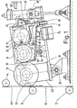
- the sheet metal strip 11 comes from z. B. a tinning plant and runs on the rollers 12, 13 and 14 determining its path to a drying device and then into a reel plant.
- the sheet metal strip 11 is touched and marked by the marking roller 15. Any marking pattern on the marking roller 15 is conceivable. As a rule, continuous thin lines are marked on the metal strip 11.
- the marking roller 15 receives the liquid for marking through the wetting roller 16. Wetting contact means that a gap of 0.01 to 0.05 mm must remain between the rollers, depending on the thickness of the liquid film on the rollers.
- the roller 16 receives the marking fluid from the roller 17. This is immersed in the bowl 19 filled with the marking fluid 18.
- the shell 19 and the rollers 16 and 17 are trough-shaped in the lower region trained swivel frame 25 to catch dripping or splashing marking fluid.
- Fig. 1 shows the marking device in the working position.
- the cylinder housing goes down.
- the frame 21 is pivoted downward about the axis of rotation 22, as a result of which the marking roller 15 is lifted off the sheet metal strip 11 because the marking roller 15 is connected to the frame 21 via the lever arm 23.
- the piston In the rest position, the piston is at the top of the cylinder.
- the air is released in the short-stroke cylinder 34 as well as in the bellows 24, so that the pivot unit 25 is also pivoted downward about the axis of rotation 26.
- the marking rollers 15 and the roller 16 are separated from one another at least to the extent that no connecting liquid film remains between them.
- the bowl 19 comes into such an inclined position that all the marking liquid runs through the overflow 38 and an outlet 28 into a container (not shown).
- the pressure spring 32 separates the roller 17 from the roller 16 when the short-stroke cylinder 34 is depressurized.
- the roller 17 was fixed in a precisely defined position because the air-actuated short-stroke cylinder 34 presses against the bearing housing of the roller 17 and presses it against the pressure of a compression spring 32 against an adjustable stop 33.
- the stop 33 is set so that the gap between the rollers 16 and 17 z. B. is 0.01 mm.
- the short-stroke cylinder 34, the compression spring 32 and the stop 33 are present on both bearing sides of the roller 17 in the same design. For the sake of simplicity, the conditions for the other roles are described below for only one bearing side.
- the position of the swivel frame 25 is adjusted so that an approximately 0.01 mm wider wetting contact gap remains between the rollers 15 and 16.
- a standby position is achieved when the cylinder housing of the pneumatic cylinder 20 moves from a lower rest position upwards in the direction of the marking position until the switching element 39 located on the cylinder housing switches the electrical switch 42, as a result of which the air supply to the cylinder 20 is interrupted by a solenoid valve (not shown). In the ready position, the marking roller 15 does not yet touch the metal strip 11.
- the marking roller 15 In the ready position, the marking roller 15 extends with its outermost left boundary up to the dashed line 40.
- the bellows cylinder 24 and the short-stroke cylinder 34 are filled with air so that the bearings of the rollers are pressed against the manually adjustable stops 33 and 35, as a result of which the rollers 15, 16 and 17 touch each other.
- the bowl 19 is filled with a marking fluid 18 up to the overflow 27 by a pump (not shown) or by hand, as a result of which the roller 17 receives its immersion depth.
- the rotary drive of the rollers is already switched on in the standby position.
- the marking device is transferred to the marking position extremely quickly.
- the bowl 19 can be pivoted about the pivot point 30 in such a way that the level of the marking liquid is raised or lowered slightly, which enables fine adjustment.
- the marking rollers 15 can be changed in a known manner by pulling them out and pushing them in from the side or by lifting them upwards out of their storage.
- the new marking roller 15 is not exactly the same diameter as the previous marking roller. Differences in diameter result from manufacturing inaccuracies or wear.
- adjustable stops 35, 37, 33 attached to the bearings of the rollers 15, 16 and 17 in an alignment device are extremely accurate to the z. B. adapted smaller diameter.
- the roller to be aligned is placed with the bearings and stops in the alignment bracket 51 shown in FIG. 3, which is provided with a storage trough from which the upper half of the roller protrudes freely.
- This alignment bracket has a horizontal support surface 52 on which a ruler 53 is placed and pressed against the roller.
- the edge of the ruler touches the roll in a straight line parallel to the rotation axis of the roll at the height of this rotation axis.
- the stops on the bearings of the roller are set with their vertical stop surfaces so that the edge of the ruler also fits snugly there.
- the roller 15 With a smaller diameter than the target diameter z. B. the roller 15, the ruler on the vertical abutment surfaces 37 a and 35 b, while there is a gap between the ruler and the roller 15.
- the stops 37 a and 35 b z. B. adjusted by an adjusting spindle so that the perpendicular stop surfaces in the direction transverse to the rotation axis of the roller until the ruler fits snugly against the roller without a gap. If the roll is too large, the stop is adjusted in the opposite direction. According to this principle, all 3 rollers 15, 16 and 17 are precisely preset with their stops.
- the marking roller 15 is mounted on a bearing side in the bearing housing 54.
- the adjustable stop 37 a is mounted on the bearing housing 54. This presses during the marking by the force of the pneumatic cylinder 20 against the non-adjustable stop 37 b, which z. B. is attached to the floor of the operating hall.
- the gap between the rollers 15 and 16 is kept constant.
- the stops 35 a and 35 b are adjustable. The same principle applies to the roller 17 and the opposing bearings of the rollers 15, 16 and 17, not shown.
- the stops set in the alignment bracket 51 are no longer readjusted when the rollers are later installed in the marking device.
- the marking device is immediately ready for operation after installation of the rollers 15, 16 and 17 in its rest position. No further readjustment is permissible in the marking position, but is not necessary, so that there are no incorrect markings in this position in the case of the rapidly moving sheet metal strip 11.
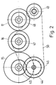
- the marking device is driven by a motor, not shown, which drives the gear 44, which is in engagement with the gear 45, which is fixed on an extension of the shaft of the marking roller 15.
- the toothed belt pulley 46 is fastened on the shaft of the toothed wheel 44.
- the other rollers 16 and 17 are also driven by means of the toothed belt pulleys 47 and 48.
- the toothed belt pulley 49 only serves to deflect and tension the double toothed belt 50.
Landscapes
- Engineering & Computer Science (AREA)
- Mechanical Engineering (AREA)
- Coating Apparatus (AREA)
- Credit Cards Or The Like (AREA)
- Treatment Of Fiber Materials (AREA)
Applications Claiming Priority (2)
| Application Number | Priority Date | Filing Date | Title |
|---|---|---|---|
| DE3738779 | 1987-11-14 | ||
| DE19873738779 DE3738779C1 (de) | 1987-11-14 | 1987-11-14 | Markiervorrichtung |
Publications (2)
| Publication Number | Publication Date |
|---|---|
| EP0316641A2 true EP0316641A2 (fr) | 1989-05-24 |
| EP0316641A3 EP0316641A3 (fr) | 1989-10-18 |
Family
ID=6340538
Family Applications (1)
| Application Number | Title | Priority Date | Filing Date |
|---|---|---|---|
| EP88117976A Withdrawn EP0316641A3 (fr) | 1987-11-14 | 1988-10-28 | Dispositif de marquage |
Country Status (4)
| Country | Link |
|---|---|
| EP (1) | EP0316641A3 (fr) |
| DE (1) | DE3738779C1 (fr) |
| ES (1) | ES2008651A4 (fr) |
| GR (1) | GR890300109T1 (fr) |
Family Cites Families (4)
| Publication number | Priority date | Publication date | Assignee | Title |
|---|---|---|---|---|
| DE1244806B (de) * | 1961-07-06 | 1967-07-20 | Gottscho Inc Adolph | Vorrichtung zum Aufdrucken von Zeichen auf horizontale Flaechen von aufeinanderfolgend vorbeigefoerderten Gegenstaenden |
| US3244139A (en) * | 1963-09-27 | 1966-04-05 | Ibm | Marking apparatus |
| DE2727043C3 (de) * | 1976-06-16 | 1980-05-08 | Fuji Photo Film Co., Ltd., Ashigara, Kanagawa (Japan) | Vorrichtung zum Drucken von Markierungen auf Stahlplatten |
| NL8303030A (nl) * | 1983-08-31 | 1985-03-18 | Korthofah Bv | Drukapparaat. |
-
1987
- 1987-11-14 DE DE19873738779 patent/DE3738779C1/de not_active Expired
-
1988
- 1988-10-28 ES ES88117976T patent/ES2008651A4/es active Pending
- 1988-10-28 EP EP88117976A patent/EP0316641A3/fr not_active Withdrawn
-
1989
- 1989-10-31 GR GR89300109T patent/GR890300109T1/el unknown
Also Published As
| Publication number | Publication date |
|---|---|
| DE3738779C1 (de) | 1988-07-07 |
| GR890300109T1 (en) | 1989-10-31 |
| EP0316641A3 (fr) | 1989-10-18 |
| ES2008651A4 (es) | 1989-08-01 |
Similar Documents
| Publication | Publication Date | Title |
|---|---|---|
| CH638763A5 (de) | Einrichtung zum automatischen versiegeln von isolierglasscheiben. | |
| DE3246129A1 (de) | Vorrichtung zum genauen anhalten von fahrzeugen | |
| DE2242993C3 (de) | Transportriementrieb | |
| CH660352A5 (de) | Ablegeeinrichtung fuer plattenfoermige werkstuecke. | |
| DE2359413C3 (de) | Vorrichtung zum Beschichten laufender Werkstoffbahnen aus Papier, Karton, Kunststoff o.dgl. | |
| DE2805211B2 (de) | Vorrichtung zum Längsschneiden von Materialbahnen | |
| DE2803132B1 (de) | Weitgehend automatisch arbeitende Vorrichtung zum beidseitigen Beschichten von Abstandhalterrahmen fuer Mehrscheiben-Isolierglas mit einer Dichtmasse und Verfahren zur Steuerung der Vorrichtung | |
| DE3738779C1 (de) | Markiervorrichtung | |
| EP0901839B1 (fr) | Dispositif pour l'application de fluides sur un substrat | |
| DE2734325A1 (de) | Vorrichtung zum selbsttaetigen regeln eines bandlaufs | |
| DE3034674C2 (de) | Wickelrollenträger | |
| DE2137706B2 (de) | Vorrichtung zum seitlichen Führen einer Materialbahn für beide Laufrichtungen | |
| EP0099349A2 (fr) | Dispositif pour appliquer une couche mince d'une matière de revêtement liquide sur une feuille | |
| DE682295C (de) | Verfahren zum passerhaltigen und registerhaltigen Bedrucken einer Papierbahn | |
| DE2314531A1 (de) | Walzenauftragmaschine zum einseitigen beschichten plattenfoermiger zuschnitte | |
| DE2741259A1 (de) | Vorrichtung zum einoelen eines band- oder tafelfoermigen bleches | |
| DE3530352C2 (fr) | ||
| DE3739873C1 (de) | Verfahren und Vorrichtung zum Beschichten eines bahnfoermigen Substrats | |
| DE1497400C3 (de) | Vorrichtung zum Einführen von Filmstreifen in Filmtaschen | |
| DE10022382C2 (de) | Vorrichtung zum Verlagern einer laufenden Warenbahn | |
| DE4213863C2 (de) | Vorrichtung zum Verbinden einer Papierbahn mit einem Papierbahn-Einfädelteil | |
| DE69307584T2 (de) | Vorrichtung zum Aufbringen einer Klebstoffschicht auf ein Endlosband und mit dieser Vorrichtung versehene Druckvorrichtung | |
| DE3612096A1 (de) | Verfahren und vorrichtung zur korrektur der bewegungsrichtung eines bahnfoermigen materials | |
| DE3121204A1 (de) | Verteilvorrichtung zur abgabe von papierbahnen mit kleberaendern | |
| DE2834603C2 (de) | Vorrichtung zum periodischen Zuführen einer Packstoffbahn |
Legal Events
| Date | Code | Title | Description |
|---|---|---|---|
| PUAI | Public reference made under article 153(3) epc to a published international application that has entered the european phase |
Free format text: ORIGINAL CODE: 0009012 |
|
| AK | Designated contracting states |
Kind code of ref document: A2 Designated state(s): AT BE CH DE ES FR GB GR IT LI LU NL SE |
|
| GBC | Gb: translation of claims filed (gb section 78(7)/1977) | ||
| ITCL | It: translation for ep claims filed |
Representative=s name: RICCARDI SERGIO & CO. |
|
| TCNL | Nl: translation of patent claims filed | ||
| EL | Fr: translation of claims filed | ||
| PUAL | Search report despatched |
Free format text: ORIGINAL CODE: 0009013 |
|
| AK | Designated contracting states |
Kind code of ref document: A3 Designated state(s): AT BE CH DE ES FR GB GR IT LI LU NL SE |
|
| STAA | Information on the status of an ep patent application or granted ep patent |
Free format text: STATUS: THE APPLICATION IS DEEMED TO BE WITHDRAWN |
|
| 18D | Application deemed to be withdrawn |
Effective date: 19900419 |