EP0316931A2 - Machine pour fonçage de puits - Google Patents
Machine pour fonçage de puits Download PDFInfo
- Publication number
- EP0316931A2 EP0316931A2 EP88119203A EP88119203A EP0316931A2 EP 0316931 A2 EP0316931 A2 EP 0316931A2 EP 88119203 A EP88119203 A EP 88119203A EP 88119203 A EP88119203 A EP 88119203A EP 0316931 A2 EP0316931 A2 EP 0316931A2
- Authority
- EP
- European Patent Office
- Prior art keywords
- water
- slurry
- muck
- shaft
- pump
- Prior art date
- Legal status (The legal status is an assumption and is not a legal conclusion. Google has not performed a legal analysis and makes no representation as to the accuracy of the status listed.)
- Granted
Links
Images




Classifications
-
- E—FIXED CONSTRUCTIONS
- E21—EARTH OR ROCK DRILLING; MINING
- E21F—SAFETY DEVICES, TRANSPORT, FILLING-UP, RESCUE, VENTILATION, OR DRAINING IN OR OF MINES OR TUNNELS
- E21F13/00—Transport specially adapted to underground conditions
- E21F13/04—Transport of mined material in gravity inclines; in staple or inclined shafts
- E21F13/042—Vertical hydraulic conveying of coal
-
- E—FIXED CONSTRUCTIONS
- E21—EARTH OR ROCK DRILLING; MINING
- E21D—SHAFTS; TUNNELS; GALLERIES; LARGE UNDERGROUND CHAMBERS
- E21D1/00—Sinking shafts
- E21D1/03—Sinking shafts mechanically, e.g. by loading shovels or loading buckets, scraping devices, conveying screws
- E21D1/06—Sinking shafts mechanically, e.g. by loading shovels or loading buckets, scraping devices, conveying screws with shaft-boring cutters
-
- E—FIXED CONSTRUCTIONS
- E21—EARTH OR ROCK DRILLING; MINING
- E21D—SHAFTS; TUNNELS; GALLERIES; LARGE UNDERGROUND CHAMBERS
- E21D5/00—Lining shafts; Linings therefor
- E21D5/04—Lining shafts; Linings therefor with brick, concrete, stone, or similar building materials
Definitions
- the present invention relates to a method for constructing a great deep shaft having a depth of e.g., more than hundreds meters. Further, the present invention is concerned with a machine suitable to perform the method above.
- the conveyance of the muck can be continuously performed because the muck can be lifted up to the inlet of the shaft by filling the shaft with the water.
- a peripheral wall of the shaft cannot be subjected to a primary lining or shotcrete made of a concrete because the shaft is filled with the water.
- an expensive excavator having properties such as watertight, waterproof and the like must be used for construction of the shaft. Further, the excavator must be drawn up when the excavator is maintained outside of the shaft, or the water filled in the shaft must be pumped up when it is maintained in the shaft.
- an object of the present invention is to obviate defects of the conventional methods and provide a method for constructing efficiently a shaft of a great depth, which can reduce a term and cost of the construction of the shaft.
- Another object of the present invention is to provide a machine suitable to perform the method above, which can excavate effectively muck generated by excavating a soft rock from a working face to an upper inlet of the great deep shaft.
- a method for constructing a shaft formed by excavating soft rock substantially vertically to form the shaft by means of an excavator comprising steps:
- a machine for constructing shaft comprising a body of an excavator to be in a shaft excavated; a water supplement means for pouring water into a working face in the shaft and controlling the amount of flowing water to keep constantly a water level of the working face; a mucking apparatus for mixing the water and muck excavated from the working face to obtain a slurry and pumping up the slurry; a slurry-conveying apparatus for conveying the slurry to outside of the shaft; and a spray apparatus for spraying concrete toward a peripheral wall exposed above the water level of the shaft to form a shotcrete.
- FIGS. 1 to 3 show a machine represented by character A according to this invention, the machine A constructing a great deep shaft having a substantially circular cross-section.
- numeral 1 denotes a flying scaffold comprising an upper plate 1a, a middle plate 1b, a lower plate 1c and connecting members 1d for connecting between two of the plates 1a to 1c.
- Each of plates 1a to 1c having a circular cross-section includes a pair of circular faces having the same area as to each other and a peripheral face being formed along a peripheral portion of the circular faces.
- Each of outer diameter of the plates 1a to 1c is set up to be smaller than an inner diameter of a shaft to be drill.
- a plural grippers 3 for keeping an attitude of the scaffold 1 are disposed on each peripheral face of the plate at equal intervals. Namely, one ends of the grippers 3 are fixedly connected at the peripheral face of the plate and the other ends are extended to a wall of the shaft to bring the other end into contact with the wall.
- the upper plate 1a and the middle plate 1b are connected with the connecting members 1d, and the middle plate 1b and the lower plate 1c are connected with the same members as above.
- opposite ends of the connecting members 1d are fixedly connected at the peripheral portions of the circular faces thereof at equal intervals without rolling the scaffold 1 or twisting it.
- Three or more of the connecting members 1d are preferably used in connection between two plates.
- a plural sheaves 2 for suspending the scaffold 1 into the shaft are disposed on the upper plate la.
- the flying scaffold 1 is suspended from an upper inlet to a bottom of the shaft by the sheaves 2 and is kept an attitude thereof by the grippers 3.
- Numeral 4 denotes an excavator having a substantially rod-shaped, comprising opposite ends. One end or an upper end of the excavator 4 is rotatably and downward supported at the central portion of the lower plate 1c. The other end or a lower end extended downward has a bit 4a for excavating soft rock of the bottom of the shaft.
- a shaft having an optional cross-section can be formed by using the excavator 4 because the bit 4a disposed on the lower end of the excavator 4 can be rotated.
- a first conveying apparatus 5 or mucking apparatus for conveying muck to be excavated to the following apparatus is disposed on the lower plate 1c, and a second conveying apparatus 6 or slurry-conveying apparatus for conveying slurry suspending the muck to the upper inlet of the shaft is disposed on an upper face of the middle plate 1b.
- the first conveying apparatus 5 comprises a pump 7 for generating a jet water, a crasher 10 for crashing the muck drawn up from the bottom of the shaft using the jet water so as to be a small size, a tank 8 for introducing a mixture including the crashed muck and the water, a pump 9 for agitating the mixture to obtain slurry and a slurry pump 11 for conveying the slurry to the second conveying apparatus 6.
- the pump 7 supplied water including no muck by a pipe 12 is connected with one end of a pipe 13 for ejecting the jet water generated by the pump 7.
- the other end of the pipe 13 passes through the lower plate 1c to extend downward to a near lower end of a pipe 14 for excavating the muck.
- One end of the pipe 14 is rotatably supported at the central portion of the lower face of the lower plate 1c and the other end thereof or a lower end is extended downward to be connected with a near position of the bit 4a of the excavator 4 so as to accompany the excavator 4 with the pipe 14.
- An inlet 15 for drawing up the muck and the water to introduce them into the pipe 14 is disposed at the lowest end of the pipe 14.
- the muck and the water are drawn up by virtue of an upward flow generated by the jet water of the pump 7 to to be introduced into the pipe 14 and supplied to the crasher 10.
- the muck is ground to have a small grain size.
- Such muck and the water are introduced into the tank 8 and agitated by the pump 9 to obtain slurry.
- the slurry is conveyed through a conveyance pipe 16 to the second conveying apparatus 6 by the slurry pump 11.
- the pipe 12 linked with the pump 7 is connected with a supplement pipe 17.
- the supplement pipe 17 is connected through a suction pipe 35 of a main pump 22 as described below with a comeback pipe 37.
- the supplement pipe 17 is also connected with both the tank 8 and the slurry pump 11 in order to supply water thereinto.
- the supplement pipe 11 is connected with a pipe 18 for supplying water to working face of the shaft.
- the pipe 18 has a valve 19 for controlling flow rate thereof. Gate opening of the valve 19 is controlled on the basis of water level of the working face measured by a water gauge 20 to adjust content of water supplied to the working face.
- the water level is determined by a water supplement means 21 for supplying water to the working face so as to be constantly kept.
- the water supplement means 21 comprises the pipe 18, the valve 19 and the water gauge 20.
- a plural arrows show flows of water or slurry.
- the second conveying apparatus 6 comprises the main pump 22, a pair of tanks 23a and 23b, and two filters 24a and 24b disposed in the tanks 23a and 23b, respectively, each filter filtrating slurry filled in the tank to drain water from the tanks.
- the tanks 23a and 23b are connected through check valves 25a and 25b with blanch pipes 16a and 16b divided from the conveyance pipe 16, respectively.
- the check valves 25a and 25b serve to prevent slurry of the tanks 23a and 23b from flowing into the conveyance pipe 16.
- the tanks 23a and 23b are also connected through check valves 27a and 27b with blanch pipes 26a and 26b divided from one end of a conveyance pipe 26.
- the other end of the conveyance pipe 26 is extended to the upper inlet of the shaft in order to convey muck of a slurry to outside of the shaft.
- the filters 24a and 24b are connected with header pipes 28a and 28b. These pipes 28a and 28b are connected to each other by pipes 29 and 30.
- the pipe 29 has valves 31 and 32, and the pipe 30 has valves 33 and 34.
- the suction pipe 35 of the main pump 22 is connected with the pipe 29 between the valves 31 and 32.
- a delivery pipe 36 of the main pump 22 is connected with the pipe 30 between the valves 33 and 34.
- the slurry is conveyed through the filters 24a or 24b in the tanks 23a or 23b to be stored therein.
- the muck of the slurry already reserved in the tanks 23b or 23a is conveyed to outside of the shaft. According to the apparatus 6, the muck can be continuously excavated to convey to outside of the shaft.
- the slurry is introduced through the check valve 25a into the tank 23a.
- the slurry conveyed from the tank 23a is filtrated by the filter 24a, so that muck of the slurry is stored in the tank 23a.
- the water passed through the filter 24a is conveyed through the filter 24b to the tank 23b and conveyed together the muck already reserved in the tank 23b through the check valve 27a to the conveyance pipe 26 extended to outside of the shaft.
- valves 31 and 34 are closed, and the valves 32 and 33 are opened.
- direction of the slurry flow is contrary to that of the previous flow.
- water of the slurry is gradually reduced in the tank 23b and then obtain the muck.
- the muck already reserved in the tank 23a is conveyed to the conveyance pipe 26.
- the muck is excavated to outside of the shaft and then is separated the muck from the water.
- the water separated from the slurry is supplied through the comeback pipe 37 to the main pump 22.
- a part of the water is also supplied through supplement pipe 17 to the pump 7, the tank 8 and the slurry pump 11 of the first conveying apparatus 5 and the water of the apparatus 5 is further supplied through the supplement pipe 18 to the working face in the shaft by virtue of the water supplement means 21.
- the thus-described machine A has a spray apparatus 38 for spraying concrete toward the peripheral wall of the shaft to form a shotcrete thereon.
- the apparatus 38 comprises a spraying pipe 39 and a concrete supplement apparatus 40 for supplying the concrete to the spraying pipe 39.
- one end of the spraying pipe 39 is rotatably supported at the lower plate 1c of the scaffold 1 so as to rotate along the peripheral wall about an axis of the lower plate 1c and the other end or a lower end of the pipe 39 is capably extended along the axis of the lower plate 1c to the near water face of the shaft.
- a spraying nozzle 39a is disposed at the lowest end of the pipe 39 and faced to the peripheral wall.
- the concrete supplement apparatus 40 is disposed on the upper plate 1a.
- Numeral 41 in FIG. 2 denotes an oil pressure unit for actuating a plural pumps as described above. Also, numeral 42 in FIGS. 2 and 3 denotes a gate for passing machines or goods such as tools and the like through. A dust collector (not shown) is disposed on the upper plate 1a of the scaffold 1.
- the flying scaffold 1 is suspended into the shaft by virtue of the sheave 2 and then kept the attitude of the scaffold 1 by using the grippers 3.
- Water represented by character W is introduced into the bottom of the shaft by the water supplement means 21 so that the machine A is partially immersed in the water W, namely only the bit 4a of the excavator 4 is submerged therein.
- the drilling is performed by the excavator 4 and then the first and second conveying apparatuses 5 and 6 are actuated, in the order.
- the muck drilled from the working face of the shaft are changed into the slurry to be excavated to outside of the shaft.
- the water level of the water W is constantly kept by virtue of the water supplement means 21.
- the peripheral wall exposed above the face of the water W is subjected to spray of concrete to form the primary shotcrete thereon.
- distance of the water face to the wall being performed the primary shotcrete is preferably shorten.
- the distance represented by character 1 is between about 1 meter and 3 meters.
- the machine A including the excavator 4 and another apparatus assembled thereinto is required of having no properties such as watertight, waterproof and the like because the level of the water W is constantly kept so that the machine A is partially immersed in the water W. Also, since the water W is shallow, the maintenance of the machine A such as exchange of bits and the like can be easily and promptly performed in the bottom of the shaft or a shaft to be constructed.
- the muck of the working of the face can be continuously and efficiently excavated by means of the first and second conveying apparatuses 5 and 6 in comparison with conventional method using kibbles or buckets to excavate the muck.
- the second conveying apparatus 6 can have an output power sufficient for lifting up a large amount of the muck from the bottom of the shaft to the upper inlet thereof, so it can be reduced a term and a cost of the construction of the shaft.
- the main pump 21 for conveying slurry upward is subjected to water pressure corresponding to distance between the pump 21 and the upper inlet of the shaft or depth of the pump 21. Therefore, the output power of the pump 21 can be reduced by the water pressure subjected thereto to save energy generated thereby.
- a shotcrete can be promptly formed on the peripheral wall of the shaft by spraying concrete toward the peripheral wall above the water level of the water W before the peripheral wall is broken. Therefore, the excavation according to the method can be performed in safety even if water is suddenly sprang up from the working face.
- one or more of the second conveying apparatus 6 as relaying apparatuses may be replaced on the way to the upper inlet of the shaft on the occasion that a shaft to be drilled has a great deep, and that the slurry cannot be conveyed by using the apparatus 6 having power insufficient for conveying it from a bottom of the shaft to an upper inlet thereof.
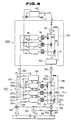
- FIGS. 5 to 8 show another variation of the second conveying apparatus 6 as described above.
- Numeral 100 denotes a primary conveying apparatus.
- the primary conveying apparatus 100 comprises a first jet pump 120, an actuation pump 121, a water supplement pipe 122, a conveyance pipe 123 and an agitation tank 124.
- the jet pump 120 is a pump for pumping up muck together the water W by suction generated because of a jet water supplied through the water supplement pipe 122 from the actuation pump 121 and then conveying the muck through the conveyance pipe 123 to the agitation tank 124.
- the agitation tank 124 the muck is mixed with water to be obtained slurry.
- the slurry is introduced through a slurry supplement pipe 125 into three kinds of tanks Ta, Tb and Tc, and top water of the slurry in the tank 124 is repeatedly come back through a comeback pipe 126 to the working face.
- Each of the pressure tanks Ta, Tb and Tc has contents sufficient for introducing a predetermined amount of the slurry. Although each tank is shown as a horizontal type in FIG. 5, it is constructed in a vertical one in practical use. Bottoms of the pressure tanks Ta, Tb and Tc are connected through check valves 127a, 127b and 127c with the slurry supplement pipe 125, respectively. Tops of the pressure tanks Ta, Tb and Tc are connected with one ends of header pipes 130a, 130b and 130c, respectively. The other ends of the header pipe 130a, 130b and 130c are connected with main ports P1 of three-port-connection-valves Va, Vb and Vc. Further, filters Fa, Fb and Fc for passing through water of the slurry and for barring muck thereof are disposed on the way between the pressure tanks and the three-port-connection-valves, respectively.
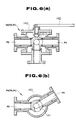
- each of the three-port-connection- valves Va, Vb and Vc comprises a substantially cylindrical valve cage 140 and a substantially spherical valve element 141 rotatably disposed therein.
- the valve cage 140 includes the main port P1 being disposed vertically at the bottom thereof, an outlet port P2 and an inlet port P3 each being disposed horizontally at the side portions.
- a lever 142 for rotating the valve element 141 is connected with a top portion of the valve element 141. By operating the lever 142, the outlet port P2 or the inlet port P3 and the main port P1 can be selectively connected to each other.
- FIG. 6 shows the three-port-connection-valve connecting the main port P1 with the inlet port P3.
- the outlet ports P2 of the three-port-connection-valves Va, Vb and Vc are connected with blanch pipes 150a, 150b and 150c divided from a water supplement pipe 150, respectively.
- the inlet ports P3 are connected with blanch pipes 151a, 151b and 151c divided from a drain pipe 151, respectively.
- a second actuation pump 152 is disposed on the way of the water supplement pipe 150, and a second jet pump 153 having property and power the same as the first jet pump 120 as described above is disposed on the way of the drain pipe 151.
- the actuation pump 152 is a pump for supplying water through the three port connection vale and the filter to one of the pressure tanks, e.g., the tank Ta as shown in FIG.
- the second jet pump 153 is a pump for pumping up only water through the filter and the three-port-connection-valve from one of the tanks, e.g., the tank Tc as shown in FIG. 5, by using suction generated because of a jet water supplied through a jet water supplement pipe 154 from the first actuation pump 121, to thereby store muck of the slurry in the tank Tc.
- the jet pump 153 is a pump for coming back the water pumped up through a comeback pipe 155 to the first actuation pump 121, and further for supplying a part of the water pumped up, through a water supplement pipe 156 to the working face.
- An amount of the water supplied from the jet pump 153 to the working face is controlled on the basis of a gate opening of a valve 157 disposed on the way of the water supplement pipe 156 so that the water level of the working face is constantly kept.
- An inlet of the main pump 152 and an outlet of the jet pump 153 are connected by a pipe 158 for supplying directly water of the water supplement pipe 150 to the working face.
- One of the three-port-connection-valves Va, Vb and Vc is set up to synchronize with another.
- valves Va, Vb and Vc The synchronization of the valves Va, Vb and Vc will now be described below with reference to FIGS. 7 and 8.
- the gate opening of the valves Va, Vb and Vc, which correspond to the working time, are shown in the order from upper to lower portion of FIG. 7.
- Opening and closing of the valve are repeatedly performed at a cycle time or period represented by character T.
- the valves are actuated to have a time lag represented by character t1 to each other.
- the valve Va is actuated as follows.
- the outlet port P2 is full opened as shown in FIG. 8(a) during the time t1. Subsequently, the outlet port P2 is gradually closed and then the inlet port P3 is gradually opened during a time t2. As the result, the inlet port P3 is full opened as shown in FIG. 8(b) and then this state is kept during a time t3. Subsequently, the inlet port P3 is gradually closed as shown in FIG. 8(c) and the inlet and outlet ports P3 and P2 are full closed together as shown in FIG. 8(d) and the outlet port P2 is gradually opened as shown in FIG. 8(e) and then the outlet port P2 is full closed again as shown in FIG. 8(a).
- valve Vb The same procedures as the valve Va are repeated by the valve Vb with a delayed time t1 and the same procedures as the valve Vb are repeated by the valve Vc with the delayed time t1.
- the outlet port P2 of the valve Vb is full opened as a state of full opening that of the valve Va is finished.
- the outlet port P2 of the valve Vc is full opened as the state of full opening that of the valve Vb is finished.
- the outlet port P2 of the valve Va is full opened again as the state of full opening that of the valve Vc is finished.
- the same procedures as the outlet ports P2 are repeated by the inlet ports P3.
- one of the inlet ports P3 of another two valves is full opened and the remainder is in gradual conversion full-opening from the inlet port P3 to the outlet port P2.
- the primary conveying apparatus 100 provided the valves Va, Vb and Vc as described above, flows of water conveyed by the main pump 152 and those of water pumped up into the slurry are changed just in time. Therefore, the slurry obtained in the agitation tank 124 is pumped up by one of the pressure tank Ta, Tb and Tc to be filled thereinto. At the same time, the muck filled into another two tanks is washed away. At the same time, the slurry introduced into the remainder is in gradual conversion from pumping-up to washing-away.
- the inlet port P3 of the valve Vc is full opened.
- the water conveyed from the main pump 152 is introduced through the filter Fa into the tank Ta.
- the muck reserved into the tank Ta is washed away through a pipe 129 toward the secondary conveying apparatus 200.
- the water of the slurry reserved into the tank Tc is pumped up through the filter Fc by the jet pump 153, and the slurry of the agitation tank 124 is sucked up into the tank Tc to be increased gradually the content of the muck in the tank Tc.
- the valve Vb is in gradual conversion from pumping-up to washing-away.
- the muck is finished washing away from the tank Ta by closing the outlet port P2 of the valve Va, the muck is begun washing away from the tank Tb.
- the tank Ta is begun pumping up the muck thereinto and the tank Tc is begun to be in gradual conversion of pumping-up to washing-away.
- the primary conveying apparatus 100 three kinds of the tanks Ta, Tb and Tc can perform the following works at the same time, respectively. Namely, one of the tanks Ta, Tb and Tc washes away the muck, one of another two tanks pumps up the slurry, and the remainder is in gradual conversion of pumping-up to washing-away. By virtue of thus works of the tanks Ta, Tb and Tc, the muck can be continuously washed away from one of the tanks. Therefore, the primary conveying apparatus 100 can efficiently convey the muck of the working face to a secondary conveying apparatus 200.
- the secondary conveying apparatus 200 is an apparatus for further conveying the slurry obtained by the primary conveying apparatus 100 to the upper inlet of the shaft, comprising the essentially same elements as the primary conveying apparatus 100 except that the actuation pump 121 and the agitation tank 124 are omitted from the apparatus 100 and that a storage tank 160 is added thereinto.
- the apparatus 200 comprises three kinds of pressure tanks Ta′, Tb′ and Tc′ and a main pump 61.
- the tanks Ta′, Tb′ and Tc′ have filters Fa′, Fb′ and Fc′, and three-port-connection-valves Va′, Vb′ and Vc′, respectively.
- the slurry conveyed from the apparatus 100 is introduced through the pipe 129 into one of the tanks Ta′, Tb′ and Tc′ to reserve therein and the slurry reserved in one of another two tanks is washed away by the water supplied from the main pump 161 to be conveyed to the upper inlet of the shaft.
- the remainder of the tanks is begun to be in gradual conversion from introduction of the slurry to washing-away.
- the slurry conveyed to the upper inlet of the shaft by the secondary conveying apparatus 200 is introduced into a disposal tank 162 and then subjected to separation and the resulting solid or muck is suitably disposed.
- the water separated from the slurry is come back again to the main pump 161 and a part of the water is directly supplied through a water supplement pipe 163 to the storage tank 160.
- the water of the slurry filtrated by the filters Fa′, Fb′ and Fc′ is stored in the storage tank 160 and then come back through the water supplement pipe 150 to the main pump 152 of the primary conveying apparatus 100.
- the slurry drilled from the working face can be continuously excavated to outside of the shaft.
- a great deep shaft having a depth of, e.g., more than hundreds meters can be efficiently constructed by disposing relay apparatuses such as the secondary conveying apparatus 200 and the like on the way of the shaft on the basis of the depth of the shaft.
- the main pump 152 is subjected to hydrostatic pressure corresponding to height therefrom to the storage tank 160
- the main pump 161 is subjected to hydrostatic pressure corresponding to height therefrom to the disposal tank 162. Therefore, they can sufficiently work if they have power of overcoming friction caused between the slurry and an inner wall of the pipes and corresponding difference of density between the water and the slurry. They must have no power for conveying muck from a bottom of the shaft to the inlet. Also, they have no risk of breaking down because only water filtrated by the filters passes therethrough.
- FIG. 9 shows another variation of the primary and secondary conveying apparatuses as described above.
- a system comprising a primary and secondary conveying apparatuses 100′ and 200′ serves to drain a large amount of flood, in addition to conveying muck to outside of the shaft.
- the primary conveying apparatus 100′ has a drain pipe 170 for connecting the actuation pump 121 with the water supplement pipe 158, and the secondary conveying apparatus 200′ has a bypass pipe 171 for connecting an inlet of the storage tank 160 with the water supplement pipe 163.
- a drain pump is disposed on the way of the bypass pipe 171.
- Numerals 173 to 184 denote valves disposed on the way of the pipes, respectively.
- the ordinary works of the system as shown in FIG. 9 are substantially identical to those of the system as shown in FIG. 5. However, when the flood is suddenly generated, the following works are performed. Namely, the valves 173, 175, 176, 179, 180 and 182 are opened, and the valves 157, 174, 177, 178, 181, 183 and 184 are closed, respectively. At the same time, the three-port-connection-valves Va, Vb, Vc, Va′, Vb′ and Vc′ are worked in ordinary ways and the jet pumps 120 and 153, the actuation pump 121, the main pump 152 and 161 and the drain pump 172 are worked, respectively.
- the water W can be pumped up from the working face by the jet pump 120 and further pumped up through one tank, e.g., the tank Tc as shown in FIG. 9, the jet pump 153, the actuation pump 121, the main pump 152, another tank, e.g., the tank Ta as shown in FIG. 9 to the secondary conveying apparatus 200′.
- the pumped-up water W is pumped up through one tank, e.g., the tank Tc′ as shown in FIG. 9, the drain pump 172, the main pump 161 and another tank, e.g., the tank Ta′ as shown in FIG. 9 to the disposal tank 162.
- the system can be used as the drainage system in case of emergencies such as floods and the like.
- the jet pump 153 is used for pumping up the slurry to introduce it into the pressure tank
- a pump e.g., a slurry pump disposed on the way of the slurry supplement pipe 125 may be used for pumping up it without using the jet pump 153.
- the jet pumps 120 and 153 have many advantages such as almost no mechanical trouble, almost maintenance free and the like in comparison with the slurry pump, the slurry pump may be used.
Landscapes
- Engineering & Computer Science (AREA)
- Mining & Mineral Resources (AREA)
- Mechanical Engineering (AREA)
- Life Sciences & Earth Sciences (AREA)
- General Life Sciences & Earth Sciences (AREA)
- Geochemistry & Mineralogy (AREA)
- Geology (AREA)
- Civil Engineering (AREA)
- Structural Engineering (AREA)
- Earth Drilling (AREA)
- Treatment Of Sludge (AREA)
Applications Claiming Priority (6)
| Application Number | Priority Date | Filing Date | Title |
|---|---|---|---|
| JP290968/87 | 1987-11-18 | ||
| JP62290968A JPH01134100A (ja) | 1987-11-18 | 1987-11-18 | 掘削ずりの搬送装置 |
| JP62290970A JP2566428B2 (ja) | 1987-11-18 | 1987-11-18 | 立坑の掘削方法 |
| JP290967/87 | 1987-11-18 | ||
| JP62290967A JP2566427B2 (ja) | 1987-11-18 | 1987-11-18 | 立坑掘削装置 |
| JP290970/87 | 1987-11-18 |
Publications (3)
| Publication Number | Publication Date |
|---|---|
| EP0316931A2 true EP0316931A2 (fr) | 1989-05-24 |
| EP0316931A3 EP0316931A3 (en) | 1989-09-13 |
| EP0316931B1 EP0316931B1 (fr) | 1992-08-19 |
Family
ID=27337620
Family Applications (1)
| Application Number | Title | Priority Date | Filing Date |
|---|---|---|---|
| EP88119203A Expired EP0316931B1 (fr) | 1987-11-18 | 1988-11-18 | Machine pour fonçage de puits |
Country Status (4)
| Country | Link |
|---|---|
| US (1) | US5022789A (fr) |
| EP (1) | EP0316931B1 (fr) |
| CA (1) | CA1329399C (fr) |
| DE (1) | DE3873884T2 (fr) |
Cited By (4)
| Publication number | Priority date | Publication date | Assignee | Title |
|---|---|---|---|---|
| WO2014206688A3 (fr) * | 2013-06-25 | 2015-09-03 | Herrenknecht Aktiengesellschaft | Dispositif pour creuser un puits et procédé pour creuser un puits |
| CN112664197A (zh) * | 2021-01-27 | 2021-04-16 | 中铁工程装备集团有限公司 | 一种竖井开挖装置、大直径竖井掘进机及施工方法 |
| WO2021110996A1 (fr) * | 2019-12-04 | 2021-06-10 | Herrenknecht Ag | Dispositif de fonçage d'un trou de forage vertical |
| CN113446008A (zh) * | 2021-08-04 | 2021-09-28 | 中铁工程装备集团有限公司 | 竖井挖掘装置及其施工方法 |
Families Citing this family (4)
| Publication number | Priority date | Publication date | Assignee | Title |
|---|---|---|---|---|
| RU2422611C1 (ru) * | 2010-02-12 | 2011-06-27 | Государственное образовательное учреждение высшего профессионального образования "Южно-Российский государственный технический университет (Новочеркасский политехнический институт)" | Стволовая навесная бурильная установка |
| EP3894655B1 (fr) | 2018-12-12 | 2025-02-26 | Master Sinkers (PTY) LTD | Agencement de porte-lames |
| EP4399368A4 (fr) * | 2021-09-10 | 2025-07-30 | Optima Mining Systems Pty Ltd | Ensemble tête de coupe |
| CN116892392A (zh) * | 2023-05-04 | 2023-10-17 | 中铁十六局集团地铁工程有限公司 | 一种风井分幅扩挖施工工艺及开挖设备 |
Family Cites Families (13)
| Publication number | Priority date | Publication date | Assignee | Title |
|---|---|---|---|---|
| US1580001A (en) * | 1925-07-28 | 1926-04-06 | Bicknell Robert Henry | Excavating apparatus |
| SU130021A1 (ru) * | 1959-11-12 | 1959-11-30 | Х.И. Абрамсон | Способ креплени монолитным бетоном вертикальных шахтных стволов, пройденных по устойчивым породам с помощью буровых установок |
| GB1083322A (en) * | 1964-03-21 | 1967-09-13 | Mott Hay & Anderson | Improvements in or relating to tunnelling apparatus and methods of tunnelling |
| US3310124A (en) * | 1964-04-13 | 1967-03-21 | John T Farmer | Method and apparatus of excavation |
| JPS5246634A (en) * | 1975-10-13 | 1977-04-13 | Tekken Constr Co | Shield excavator |
| DE2657573C3 (de) * | 1976-12-18 | 1981-07-23 | Gewerkschaft Eisenhütte Westfalia, 4670 Lünen | Einrichtung zum Erweitern von Schächten o.dgl. |
| US4165129A (en) * | 1977-11-17 | 1979-08-21 | Ishikawajima-Harima Jukogyo Kabushiki Kaisha | Shield tunneling machine and method |
| SU810978A1 (ru) * | 1978-12-22 | 1981-03-07 | Ростовский Ордена Трудового Крас-Ного Знамени Государственныйуниверситет | Устройство дл нанесени набрызг-бЕТОННыХ пОКРыТий B СТВОлАХ |
| DE2942635C2 (de) * | 1979-10-22 | 1983-03-17 | Siemag Transplan Gmbh, 5902 Netphen | Rohrkammeraufgeber zum Einschleusen von im Schachtbohrverfahren gewonnenen Bergen in eine hydraulische Förderanlage |
| US4365427A (en) * | 1981-07-21 | 1982-12-28 | Chapman Jr Marion R | Suction dredge cutter head |
| FR2565290B1 (fr) * | 1984-05-29 | 1987-04-30 | Sourice Claude | Procede et dispositif de creusement de puits |
| DE3609111A1 (de) * | 1986-03-19 | 1987-10-01 | Turmag Turbo Masch Ag | Bohrmaschine |
| US5397970A (en) * | 1992-04-24 | 1995-03-14 | Texas Instruments Incorporated | Interface circuit having improved isolation among signals for use with a variable speed electrically commutated fan motor |
-
1988
- 1988-11-16 CA CA000583281A patent/CA1329399C/fr not_active Expired - Fee Related
- 1988-11-17 US US07/273,368 patent/US5022789A/en not_active Expired - Fee Related
- 1988-11-18 EP EP88119203A patent/EP0316931B1/fr not_active Expired
- 1988-11-18 DE DE8888119203T patent/DE3873884T2/de not_active Expired - Fee Related
Cited By (9)
| Publication number | Priority date | Publication date | Assignee | Title |
|---|---|---|---|---|
| WO2014206688A3 (fr) * | 2013-06-25 | 2015-09-03 | Herrenknecht Aktiengesellschaft | Dispositif pour creuser un puits et procédé pour creuser un puits |
| AU2014301480B2 (en) * | 2013-06-25 | 2017-08-03 | Herrenknecht Aktiengesellschaft | Device for sinking a shaft and method for sinking a shaft |
| US9995138B2 (en) | 2013-06-25 | 2018-06-12 | Herrenknecht Aktiengesellschaft | Device for sinking a shaft and method for sinking a shaft |
| RU2667988C2 (ru) * | 2013-06-25 | 2018-09-25 | Херренкнехт Акциенгезельшафт | Устройство для проходки шахтного ствола и способ проходки шахтного ствола |
| WO2021110996A1 (fr) * | 2019-12-04 | 2021-06-10 | Herrenknecht Ag | Dispositif de fonçage d'un trou de forage vertical |
| CN114945732A (zh) * | 2019-12-04 | 2022-08-26 | 海瑞克股份公司 | 用于挖掘竖直的钻孔的设备 |
| AU2020396287B2 (en) * | 2019-12-04 | 2025-10-16 | Herrenknecht Ag | Device for sinking a vertical borehole |
| CN112664197A (zh) * | 2021-01-27 | 2021-04-16 | 中铁工程装备集团有限公司 | 一种竖井开挖装置、大直径竖井掘进机及施工方法 |
| CN113446008A (zh) * | 2021-08-04 | 2021-09-28 | 中铁工程装备集团有限公司 | 竖井挖掘装置及其施工方法 |
Also Published As
| Publication number | Publication date |
|---|---|
| CA1329399C (fr) | 1994-05-10 |
| DE3873884D1 (de) | 1992-09-24 |
| US5022789A (en) | 1991-06-11 |
| EP0316931B1 (fr) | 1992-08-19 |
| EP0316931A3 (en) | 1989-09-13 |
| DE3873884T2 (de) | 1993-03-04 |
Similar Documents
| Publication | Publication Date | Title |
|---|---|---|
| EP0316931B1 (fr) | Machine pour fonçage de puits | |
| CN110725683B (zh) | 一种竖井掘进机用泥浆环流出渣系统 | |
| CN108005111A (zh) | 一种用作地下立体车库的竖井建造方法 | |
| CN212337200U (zh) | 一种桩基施工清孔装置 | |
| CN1025799C (zh) | 立井井筒过流砂层施工置换注浆法 | |
| CN108525356A (zh) | 一种井下水仓煤泥的处理方法 | |
| RU2078209C1 (ru) | Способ разработки месторождений полезных ископаемых и суперструктура для его осуществления | |
| US6428245B1 (en) | Method of and apparatus for transporting particulate materials from a lower level to a higher level | |
| RU2029077C1 (ru) | Способ добычи нефти | |
| CN115324582A (zh) | 一种竖井全断面掘进机上排渣系统及方法 | |
| CN111594176B (zh) | 针对戈壁地质环境的竖井掘进施工方法及竖井结构 | |
| CN110374124B (zh) | 地铁施工排水系统 | |
| CN212389286U (zh) | 一种反循环洗孔装置 | |
| CN114100204B (zh) | 深锥浓密机底流节能输送系统及其使用方法 | |
| CN213085893U (zh) | 一种水煤浆废浆液回收利用装置 | |
| CN113482570B (zh) | 一种可重复利用固井套管的施工工艺 | |
| CN105804124B (zh) | 地下工程用防突涌水压控制方法 | |
| JP2566427B2 (ja) | 立坑掘削装置 | |
| JP2566428B2 (ja) | 立坑の掘削方法 | |
| CN209228405U (zh) | 一种增加矿井水仓容量的系统 | |
| SU1719564A1 (ru) | Установка дл реагентной разглинизации скважины | |
| CN217267247U (zh) | 堰塞体防渗墙施工设备 | |
| CN119588603B (zh) | 筛分箱 | |
| CN205618116U (zh) | 一种气举反循环液面控制装置 | |
| CN205955772U (zh) | 一种封闭矿井突水区域的抢险排水系统 |
Legal Events
| Date | Code | Title | Description |
|---|---|---|---|
| PUAI | Public reference made under article 153(3) epc to a published international application that has entered the european phase |
Free format text: ORIGINAL CODE: 0009012 |
|
| AK | Designated contracting states |
Kind code of ref document: A2 Designated state(s): DE FR GB |
|
| PUAL | Search report despatched |
Free format text: ORIGINAL CODE: 0009013 |
|
| AK | Designated contracting states |
Kind code of ref document: A3 Designated state(s): DE FR GB |
|
| 17P | Request for examination filed |
Effective date: 19900309 |
|
| 17Q | First examination report despatched |
Effective date: 19910220 |
|
| GRAA | (expected) grant |
Free format text: ORIGINAL CODE: 0009210 |
|
| AK | Designated contracting states |
Kind code of ref document: B1 Designated state(s): DE FR GB |
|
| REF | Corresponds to: |
Ref document number: 3873884 Country of ref document: DE Date of ref document: 19920924 |
|
| ET | Fr: translation filed | ||
| PLBE | No opposition filed within time limit |
Free format text: ORIGINAL CODE: 0009261 |
|
| STAA | Information on the status of an ep patent application or granted ep patent |
Free format text: STATUS: NO OPPOSITION FILED WITHIN TIME LIMIT |
|
| 26N | No opposition filed | ||
| PGFP | Annual fee paid to national office [announced via postgrant information from national office to epo] |
Ref country code: GB Payment date: 19931104 Year of fee payment: 6 |
|
| PGFP | Annual fee paid to national office [announced via postgrant information from national office to epo] |
Ref country code: FR Payment date: 19931129 Year of fee payment: 6 |
|
| PGFP | Annual fee paid to national office [announced via postgrant information from national office to epo] |
Ref country code: DE Payment date: 19931130 Year of fee payment: 6 |
|
| PG25 | Lapsed in a contracting state [announced via postgrant information from national office to epo] |
Ref country code: GB Effective date: 19941118 |
|
| GBPC | Gb: european patent ceased through non-payment of renewal fee |
Effective date: 19941118 |
|
| PG25 | Lapsed in a contracting state [announced via postgrant information from national office to epo] |
Ref country code: FR Effective date: 19950731 |
|
| PG25 | Lapsed in a contracting state [announced via postgrant information from national office to epo] |
Ref country code: DE Effective date: 19950801 |
|
| REG | Reference to a national code |
Ref country code: FR Ref legal event code: ST |