EP0317090A2 - Système de bobine locale pour recevoir des signaux de noyaux résonnants - Google Patents
Système de bobine locale pour recevoir des signaux de noyaux résonnants Download PDFInfo
- Publication number
- EP0317090A2 EP0317090A2 EP88309941A EP88309941A EP0317090A2 EP 0317090 A2 EP0317090 A2 EP 0317090A2 EP 88309941 A EP88309941 A EP 88309941A EP 88309941 A EP88309941 A EP 88309941A EP 0317090 A2 EP0317090 A2 EP 0317090A2
- Authority
- EP
- European Patent Office
- Prior art keywords
- inner conductor
- conductor
- arrangement according
- coil
- magnetic resonance
- Prior art date
- Legal status (The legal status is an assumption and is not a legal conclusion. Google has not performed a legal analysis and makes no representation as to the accuracy of the status listed.)
- Withdrawn
Links
Images


Classifications
-
- G—PHYSICS
- G01—MEASURING; TESTING
- G01R—MEASURING ELECTRIC VARIABLES; MEASURING MAGNETIC VARIABLES
- G01R33/00—Arrangements or instruments for measuring magnetic variables
- G01R33/20—Arrangements or instruments for measuring magnetic variables involving magnetic resonance
- G01R33/28—Details of apparatus provided for in groups G01R33/44 - G01R33/64
- G01R33/32—Excitation or detection systems, e.g. using radio frequency signals
- G01R33/36—Electrical details, e.g. matching or coupling of the coil to the receiver
- G01R33/3621—NMR receivers or demodulators, e.g. preamplifiers, means for frequency modulation of the MR signal using a digital down converter, means for analog to digital conversion [ADC] or for filtering or processing of the MR signal such as bandpass filtering, resampling, decimation or interpolation
-
- G—PHYSICS
- G01—MEASURING; TESTING
- G01R—MEASURING ELECTRIC VARIABLES; MEASURING MAGNETIC VARIABLES
- G01R33/00—Arrangements or instruments for measuring magnetic variables
- G01R33/20—Arrangements or instruments for measuring magnetic variables involving magnetic resonance
- G01R33/28—Details of apparatus provided for in groups G01R33/44 - G01R33/64
- G01R33/32—Excitation or detection systems, e.g. using radio frequency signals
- G01R33/34—Constructional details, e.g. resonators, specially adapted to MR
- G01R33/34046—Volume type coils, e.g. bird-cage coils; Quadrature bird-cage coils; Circularly polarised coils
-
- G—PHYSICS
- G01—MEASURING; TESTING
- G01R—MEASURING ELECTRIC VARIABLES; MEASURING MAGNETIC VARIABLES
- G01R33/00—Arrangements or instruments for measuring magnetic variables
- G01R33/20—Arrangements or instruments for measuring magnetic variables involving magnetic resonance
- G01R33/28—Details of apparatus provided for in groups G01R33/44 - G01R33/64
- G01R33/32—Excitation or detection systems, e.g. using radio frequency signals
- G01R33/34—Constructional details, e.g. resonators, specially adapted to MR
- G01R33/341—Constructional details, e.g. resonators, specially adapted to MR comprising surface coils
-
- G—PHYSICS
- G01—MEASURING; TESTING
- G01R—MEASURING ELECTRIC VARIABLES; MEASURING MAGNETIC VARIABLES
- G01R33/00—Arrangements or instruments for measuring magnetic variables
- G01R33/20—Arrangements or instruments for measuring magnetic variables involving magnetic resonance
- G01R33/28—Details of apparatus provided for in groups G01R33/44 - G01R33/64
- G01R33/32—Excitation or detection systems, e.g. using radio frequency signals
- G01R33/36—Electrical details, e.g. matching or coupling of the coil to the receiver
- G01R33/3628—Tuning/matching of the transmit/receive coil
Definitions
- This invention relates to localised coil arrangements for receiving signals from resonating nuclei.
- the invention relates to localized coil arrangements for use in medical imaging equipment to receive electromagnetic signals from resonating nuclei produced in the examination region of such equipment and will be described with particular reference thereto. It is to be appreciated, however, that the invention may also find utility in other magnetic resonance and radio frequency antenna applications, such as exciting resonance, chemical analysis, well logging, and the like.
- various types of coils have been positioned to receive electromagnetic signals for magnetic resonance imaging and spectroscopy, e.g. whole body, body portion, and localized coils.
- the whole body and portion receiving coils had standard sizes which were selected for readily receiving the patient's whole body or a selected portion. Due to the standardized coil size and variable patient size, a void or empty region was commonly defined between the coil and the portion of the patient to be imaged.
- Localized or surface coils were configured from rigid or flexible non-conductive sheets on which conductive loops were mounted. Rigid, flat coils were constructed in a variety of sizes to facilitate positioning adjacent the selected area of the patient to be imaged. When a flat coil was positioned adjacent to a relatively flat area of the patient, the intervening air gap was relatively small.
- a localised coil arrangement for receiving radio frequency signals from resonating nuclei characterised in that it comprises: an inner conductor defining a first current path adjacent a surface of a subject; an outer conductor defining a current path along the inner conductor and at least partially therearound, the outer conductor being disposed between the surface of the subject and the inner conductor, the outer conductor having at least one opening therein between the subject surface and the inner conductor; a connecting means for electrically connecting adjacent first ends of the inner and outer conductors; and an interface means connected with and adjacent second ends of the inner and outer conductors for interconnecting the conductors with a cable extending to a receiver.
- a localised coil arrangement for receiving radio frequency signals from resonating nuclei characterised in that it comprises: an inner conductor defining at least one loop between first and second ends thereof; a Faraday shield means including a first conductive portion extending along the inner conductor from adjacent the first end of the inner conductor and between the inner conductor and the surface of a subject and a second conductive portion extending along the inner conductor from adjacent the second end of the inner conductor and between the inner conductor and the surface of the subject, the first and second conductive portions defining a gap therebetween; a first FET transistor having a gate connected with the first end of the inner conductor, a source connected with the Faraday shield first and second conductive portions and by a transmission cable to a receiver, and a drain connected by the transmission cable to the receiver.
- a magnetic resonance method comprising: disposing a subject in a magnetic field; disposing an inner conductor adjacent a surface of the subject; disposing an outer conductor parallel to the inner conductor and between the inner conductor and the subject, the outer conductor having an electrical discontinuity therein; connecting the outer conductor with a ground; connecting at least one end of the inner conductor with a preamplifier, which preamplifier is disposed adjacent the inner conductor and the patient surface within the magnetic field; connecting the preamplifier with a radio frequency receiver; exciting magnetic resonance of nuclei in the subject such that radio frequency magnetic resonance signals are generated; receiving the magnetic resonance signals with the inner conductor, amplifying the magnetic resonance signals with the preamplifier, and conducting the amplified magnetic resonance signals to the receiver.
- One advantage of the present invention is that in a receive mode, an improved signal to noise ratio is achieved.
- Another advantage of the present iention is that it improves the Q factor of the coil.
- Another advantage of the present invention resides in the reduction of the interaction between the localized coil and the subject.
- Another advantage of the present invention is that it enables localized coils to be operated over a wide range of frequencies, including frequencies above and below the self resonance frequency.
- Yet another advantage of the present invention resides in a completely passive interface between the localized coil and transmission cable.
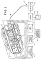
- the magnetic resonance imaging apparatus includes a main magnetic field means A for establishing a generally uniform, main magnetic field longitudinally through an image region along a z-axis.
- a gradient field means B selectively produces magnetic field gradients transversely across the main magnetic field of the image region.
- a magnetic resonance excitation means C excites magnetic resonance in selected nuclei of a patient or subject disposed in the image region.
- the resonating nuclei generate radio frequency magnetic resonance signals which are received by a surface or localized coil D. More specifically, the surface coil is disposed adjacent a preselected region of the subject to be imaged such that it receives magnetic resonance signals from nuclei disposed in the preselected region of interest.
- Electronic processing circuitry E converts the received radio frequency signals into an image representation indicative of nuclei density, relaxation time, position, nuclei characteristics, or the like.
- the main magnetic field means A includes a magnetic field control circuit 10 and a plurality of high power magnets 12.
- a gradient magnetic field control circuit or means 14 applies current pulses to gradient coils 16 to create gradients across the main magnetic field.
- the current pulse to each gradient coil is controlled by the gradient field means B to select the angular orientation of the transverse gradient field generated by a gradient field coil assembly 16.
- the resonance excitation means C includes a radio frequency transmitter 18 and transmission coil 20 to broadcast radio frequency (RF) signals that excite and manipulate magnetic resonance.
- the localized coil D may be connected with the RF transmitter to apply the RF pulses to adjacent regions of the subject.
- a central computer 22 coordinates the sequence and timing of the gradient field pulses and the RF pulses.
- the signals emitted by the relaxation of nuclei in the subject have components only in a plane that is normal to the direction of the static magnetic field, i.e. in the x-y plane, which is normal to the z-axis. Accordingly, only those conductors of the localized coil which intersect the x-y plane will detect the magnetic resonance signals. RF signals from the x-y plane induce a like RF current along the z-axis in the intersecting coil segment.
- the conductors contribute to a heavy interaction with the subject which results in Q loading and reduced sensitivity.
- the RF current pulses through a z-axis conductor of the localized coil induce magnetic fields in the x-y plane.
- Magnetic resonance signal components not in the x-y planes, i.e. z-axis components are attributable solely to noise. Accordingly, it is desirable to suppress reception of the z-axis RF field components.
- the localized coil D includes a first or inner conductor 30 which defines a current path or loop along a surface of the subject adjacent the region of interest.
- a second or outer conductor or Faraday shield 32 extends parallel to the inner conductor and peripherally therearound.
- An electrical interconnection 34 interconnects first ends of the inner and outer electrical conductors.
- An electrical interface 36 couples the localized coil, particularly the second ends of the inner and outer conductors, with a flexible transmission cable 38.
- the flexible cable 38 connects the localized coil with the remotely located processing circuitry E. More specifically, the cable conveys the received radio frequency signals from the localized coil to a radio frequency receiver 40.
- An imager 42 reconstructs an image representation from the received magnetic resonance signals and the magnetic field control and timing information from the central processor 22.
- the electronic image representation may be converted to a man-readable display by a video monitor or other display means 44.
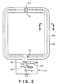
- the localized coil is a loop of coaxially constructed conductors closed upon itself.
- the inner or center conductor 30 is shorted 34 to the outer conductor 32.
- the outer conductor includes segments of copper tubing 32 which are discontinuous at a gap or opening 50.
- the inner conductor 30 is the center core of a coaxial cable separated from the outer conductor 32 by a dielectric insulator 52.
- the inner conductor 30 becomes a signal output and the outer conductor 32 is electrically interconnected with each other and a ground 54.
- the first and second ends of the coil are disposed adjacent the interface 36 and the gap 50 is disposed diametrically opposite.
- the self resonance of the coaxial cable is governed in significant part by the inductance of the inner conductor and the shunt capacitance of the center conductor to the outer shield. Reducing the shunt capacitance raises the self resonance and Q value of the coil.
- the shunt capacitance can be reduced by increasing the diameter of the outer conductor or by reducing the dielectric constant of the inter-conductor insulating material 52. Higher velocity factor dielectrics for a given conductor geometry will raise the characteristic impedance and typically the Q value. Air is a suitable high velocity dielectric and is typically less lossy than materials with a high dielectric constant, hence lower velocity factor.
- the interface circuit 38 includes a variable capacitor 60 for adjusting the resonant frequency of the coil. If the coil were operated above its parallel self resonant frequency, the coil would appear capacitive at the operating frequency. To cancel this capacitive reactance, an inductor 62 is connected in parallel with the capacitor 60 across the inner and outer conductors to enable the coil to be tuned to resonance.
- a preamplifier means 64 includes a single junction FET 66 connected in a common source configuration. That is, the inner conductor 30 is connected with the gate of the transistor. The source, like one end of the capacitor and inductor, is connected with the ground
- the drain is connected with the transmission cable 38 to receive motive power therefrom, specifically a DC bias.
- a DC bias Connecting the FET in a common source configuration allows the high impedance localized coil to see a high impedance load while driving a lower impedance cable, typically 50 ohms.
- the preamplified output from the transistor is conveyed superimposed with the DC bias on a pair of coaxial leads of the transmission cable 38.
- a pair of high speed switching diodes 68 are connected back to back across the coil and the system ground to protect the FET from excessive RF voltage during RF pulse transmission.
- the localized coil D appears electrically as a parallel resonance structure trimmed to a selected frequency by the variable capacitor 60 and, if necessary, the inductor 62.
- the Faraday shielding renders the coil relatively insensitive to electrostatic fields from the environment.
- the electrostatic field generated by excitation of the coil by external means, such as the radio frequency resonance excitation signal is substantially contained between the inner and outer conductors of the coil.
- the coil couples magnetically to the environment because the inner loop is viewed from outside of the coil, whereas the outer conductor or shield is not a closed loop.
- An incident magnetic field perpendicular to the x-z plane in which the coil lies induces a potential across the output of the coil to the gate of the transistor 66.
- the level of this potential is increased by the Q value of the coil in proportion to the square root of the Q. Because the Q value of the coil is damped by the magnetic coupling of the coil and the sample, and not by the electrostatic coupling, the available signal is greater than that obtained by an ordinary coil of similar size. Further, because the electrostatic field does not couple outside of the fixed coil geometry, the tuning of the coil is relatively unaffected by the sample.
- the input of the transistor 66 appears as a near open circuit which minimizes the effect of the transistor on the coils Q value. Further, impedance matching is not required. The coil effectively does not deliver power into the load.
- the FET input impedance sees the equivalent parallel resistance of the coil at resonance which, of course, is a function of the Q value. Because the transistor is physically adjacent the coil, the equivalent noise input voltage as defined by the transistor noise figure and the thermal noise tracks the coil impedance defined by the loaded Q value over a wide range of impedances.
- the transistor is an FET of a type selected to have an IDSS on the same order as the ID specification for the best noise figure.
- a DC power supply 70 is mounted in conjunction with the receiver 40 for applying a DC bias to the coaxial leads of the transmission cable 38. Specifically, a DC bias voltage source 72 is superimposed on the transmission line by a decoupling impedance 74. A DC blocking capacitor 76 blocks the DC bias voltage from reaching the input stage of the receiver 40.
- the outer conductor 32 need not completely surround the inner conductor 30 in order to shield against electrostatic field losses. Rather, partially surrounding the inner conductor on the side toward the surface of the subject has been found to produce satisfactory shielding.
- the interface 36 is a passive interface which is particularly advantageous for mid-field imagers and lower frequency applications.
- the passive interface includes a tuning capacitor 60 for adjusting the tuning, i.e. for adjusting the resonant frequency of the coil and interface to match the resonance signal center frequency.
- the capacitor 60 may be a varactor diode to enable the coil system to be tuned remotely by superimposing a voltage on cable 38.
- a matching capacitance 78 matches the coil with the impedance of the cable 38, e.g. a 50 ohm cable.
- an inductor may be connected in parallel to the matching capacitor to raise the self resonant frequency of the coil.
- the interface circuit 36 includes a passive impedance matching network and an active decoupling system.
- the active decoupling system includes PIN diodes 80, 82 for selectively decoupling the localized coil from the cable. Particularly, when a positive DC bias or current is superimposed on the leads of the cable 38, the diodes are biased on and appear as a very low impedance to radio frequency signals.
- the diode 82 effectively shorts out the coil deresonating it.
- the diode 80 effectively connects a capacitor 84 and an inductor 86 in parallel. The inductor is selected to parallel resonate capacitor 84 at the operating frequency, effectively decoupling the coil from the rest of the system.
- a varicap diode 88 whose capacitance is remotely adjustable is used to optimize the system performance.
- the varicap diode is biased such that adjusting a negative bias applied across the cable 38 adjusts the capacitance.
- an inductor can be added analogous to inductor 62 of FIGURE 4 to raise the self resonance frequency.
- a positive DC bias is applied to the cable 38 when the scanner is exciting magnetic resonance.
- the inductor 62 of the embodiment of FIGURES 1-6 enables physically large localized coils to be operated below their self resonance frequency.
- operation below the self resonance frequency can be achieved by connecting capacitors 90, 92 in series with the inner conductor 30.
- the outer conductors have additional gaps generally midway between the gap or opening 50 and the ends of the coil to provide access for connecting the capacitors 90, 92.
- Electrical connectors 94 such as conductive sleeves, provide electrical continuity across the capacitor access gaps.
- Other numbers of capacitors may, of course, be provided, e.g. a larger plurality of capacitors may be symmetrically or asymmetrically arranged around the coil.
- a balanced coil configuration which raises the self resonant frequency of the localized coil.
- opposite ends of the center conductor 30 are both connected with the interface circuit 36.
- An adjustable tuning reactance 60 is connected across the ends of the inner conductor to tune the resonant frequency of the coil.
- a protection diode array 68 connects the ends of the inner conductor with the ground and the outer conductor.
- the gates of a pair of FET transistors 66a, 66b are each connected to one of the inner conductors.
- the FETs are connected in a common source configuration with their sources connected to ground and their drains connected to a balun 98.
- the balun matches the balanced coil configuration to the unbalanced transmission cable 38.
- the preamplifier means 64 may include other solid state arrangements. Utilizing a MOSFET transistor offers the advantage of a higher impedance, hence, a higher coil Q value which can result in substantial gains in the signal-to-noise ratio when a level of loading on the coils is low.
- a dual gate MOSFET 100 has a first gate 102 connected with the inner conductor.
- a second gate 104 is connected with a decoupling circuit 106 which derives a second gate bias from the drain supply.
- a pair of crossed diodes 110 short the gap 50 in the outer conductor. Any incident radio frequency field of a large magnitude will cause the crossed diodes to conduct, thus shorting the gap and preventing the inner conductor from becoming visible to the RF magnetic field. In this manner, the pick up loop 30 can be isolated from the incident radio frequency magnetic resonance excitation fields.
Landscapes
- Physics & Mathematics (AREA)
- Condensed Matter Physics & Semiconductors (AREA)
- General Physics & Mathematics (AREA)
- Magnetic Resonance Imaging Apparatus (AREA)
Applications Claiming Priority (2)
| Application Number | Priority Date | Filing Date | Title |
|---|---|---|---|
| US120475 | 1987-11-13 | ||
| US07/120,475 US4839594A (en) | 1987-08-17 | 1987-11-13 | Faraday shield localized coil for magnetic resonance imaging |
Publications (2)
| Publication Number | Publication Date |
|---|---|
| EP0317090A2 true EP0317090A2 (fr) | 1989-05-24 |
| EP0317090A3 EP0317090A3 (fr) | 1990-09-05 |
Family
ID=22390542
Family Applications (1)
| Application Number | Title | Priority Date | Filing Date |
|---|---|---|---|
| EP19880309941 Withdrawn EP0317090A3 (fr) | 1987-11-13 | 1988-10-21 | Système de bobine locale pour recevoir des signaux de noyaux résonnants |
Country Status (3)
| Country | Link |
|---|---|
| US (1) | US4839594A (fr) |
| EP (1) | EP0317090A3 (fr) |
| JP (1) | JPH01160539A (fr) |
Cited By (7)
| Publication number | Priority date | Publication date | Assignee | Title |
|---|---|---|---|---|
| EP0443677A3 (en) * | 1990-02-20 | 1991-12-04 | N.V. Philips' Gloeilampenfabrieken | Quadrature surface coil construction for magnetic resonance imaging apparatus |
| DE4039409A1 (de) * | 1990-12-10 | 1992-06-11 | Siemens Ag | Verstimmeinrichtung fuer resonatoren in einem kernspinresonanz-bildgeraet |
| US5258718A (en) * | 1990-12-04 | 1993-11-02 | Siemens Aktiengesellschaft | Nuclear magnetic resonance tomography apparatus |
| WO2006000928A3 (fr) * | 2004-06-25 | 2006-03-30 | Koninkl Philips Electronics Nv | Alimentation integree pour bobines de surface |
| WO2007138547A3 (fr) * | 2006-05-30 | 2008-05-02 | Philips Intellectual Property | Desaccordage d'une bobine de radiofrequence |
| WO2013013680A1 (fr) * | 2011-07-22 | 2013-01-31 | MAX-PLANCK-Gesellschaft zur Förderung der Wissenschaften e.V. | Antenne et ensemble antenne pour applications à résonance magnétique |
| KR101326638B1 (ko) | 2005-11-28 | 2013-11-08 | 지멘스 악티엔게젤샤프트 | 자기 공진 적용을 위한 공진기 |
Families Citing this family (42)
| Publication number | Priority date | Publication date | Assignee | Title |
|---|---|---|---|---|
| EP0361190A1 (fr) * | 1988-09-23 | 1990-04-04 | Siemens Aktiengesellschaft | Dispositif de bobines de surface pour examens par résonance magnétique nucléaire |
| US5132903A (en) * | 1990-06-19 | 1992-07-21 | Halliburton Logging Services, Inc. | Dielectric measuring apparatus for determining oil and water mixtures in a well borehole |
| DE4030877A1 (de) * | 1990-09-29 | 1992-04-02 | Siemens Ag | Doppel-oberflaechenspule fuer ein kernspinresonanzgeraet |
| US5621323A (en) * | 1991-11-29 | 1997-04-15 | Magnetic Research, Inc. | Surface coil elements |
| US5432450A (en) * | 1993-03-09 | 1995-07-11 | The Five Oaks Research Institute | Truncated nuclear magnetic imaging probe |
| US5347221A (en) * | 1993-03-09 | 1994-09-13 | Rubinson Kenneth A | Truncated nuclear magnetic imaging probe |
| DE4314338C2 (de) * | 1993-04-30 | 1998-07-23 | Siemens Ag | Hochfrequenz-System einer Anlage zur Kernspintomographie mit Abschirmmitteln zu einer E-Feld-Begrenzung |
| US5898306A (en) * | 1997-04-09 | 1999-04-27 | Regents Of The University Of Minnesota | Single circuit ladder resonator quadrature surface RF coil |
| US6794255B1 (en) * | 1997-07-29 | 2004-09-21 | Micron Technology, Inc. | Carburized silicon gate insulators for integrated circuits |
| US7196929B1 (en) * | 1997-07-29 | 2007-03-27 | Micron Technology Inc | Method for operating a memory device having an amorphous silicon carbide gate insulator |
| IT1305968B1 (it) | 1998-07-09 | 2001-05-21 | Esaote Spa | Unita' di ricezione di segnali a radiofrequenza in particolare nellemacchine per il rilevamento di immagini in risonanza magnetica |
| US6344745B1 (en) | 1998-11-25 | 2002-02-05 | Medrad, Inc. | Tapered birdcage resonator for improved homogeneity in MRI |
| US6798206B2 (en) | 1998-11-25 | 2004-09-28 | Medrad, Inc. | Neurovascular coil system and interface and system therefor and method of operating same in a multitude of modes |
| US6356081B1 (en) | 1998-11-25 | 2002-03-12 | Medrad, Inc. | Multimode operation of quadrature phased array MR coil systems |
| US7598739B2 (en) * | 1999-05-21 | 2009-10-06 | Regents Of The University Of Minnesota | Radio frequency gradient, shim and parallel imaging coil |
| US6320385B1 (en) | 1999-09-17 | 2001-11-20 | Picker International, Inc. | Multi-channel balun for magnetic resonance apparatus |
| US6727698B1 (en) * | 1999-12-17 | 2004-04-27 | Fonar Corporation | MRI antennas including electrically connected inner and outer conductors, and MRI systems including such antennas |
| US6847210B1 (en) | 1999-12-17 | 2005-01-25 | Fonar Corporation | MRI antenna |
| US6636040B1 (en) | 1999-12-17 | 2003-10-21 | Fonar Corporation | MRI antenna |
| US6414488B1 (en) * | 2000-03-01 | 2002-07-02 | Koninklijke Philips Electronics N.V. | Method and apparatus for decoupling magnetic resonance receive coils |
| WO2002010786A2 (fr) * | 2000-07-31 | 2002-02-07 | Regents Of The University Of Minnesota | Unite a champ magnetique radiofrequence |
| US7023209B2 (en) * | 2000-10-09 | 2006-04-04 | Regents Of The University Of Minnesota | Method and apparatus for magnetic resonance imaging and spectroscopy using microstrip transmission line coils |
| US9295828B2 (en) * | 2001-04-13 | 2016-03-29 | Greatbatch Ltd. | Self-resonant inductor wound portion of an implantable lead for enhanced MRI compatibility of active implantable medical devices |
| US6593744B2 (en) | 2001-11-20 | 2003-07-15 | Koninklijke Philips Electronics, N.V. | Multi-channel RF cable trap for magnetic resonance apparatus |
| US7084629B2 (en) | 2002-11-27 | 2006-08-01 | Medrad, Inc. | Parallel imaging compatible birdcage resonator |
| US6927575B2 (en) * | 2003-01-21 | 2005-08-09 | General Electric Company | Surface coil decoupling means for MRI systems |
| JP3783689B2 (ja) * | 2003-02-28 | 2006-06-07 | ソニー株式会社 | アンテナ装置 |
| DE10345766B3 (de) * | 2003-10-01 | 2005-08-11 | Siemens Ag | Erzeuger zeitvariabler Magnetfelder eines Magnetresonanzgeräts und Magnetresonanzgerät mit dem Erzeuger |
| WO2005111645A2 (fr) * | 2004-05-07 | 2005-11-24 | Regents Of The University Of Minnesota | Elements a courant multiple pour bobines radiofrequences pour resonance magnetique |
| US7936171B2 (en) * | 2007-11-21 | 2011-05-03 | Brandeis University | Baluns, a fine balance and impedance adjustment module, a multi-layer transmission line, and transmission line NMR probes using same |
| JP5288462B2 (ja) * | 2008-10-06 | 2013-09-11 | 国立大学法人大阪大学 | 爆発物、不正薬物検査装置、アンテナコイルおよび爆発物、不正薬物検査方法 |
| US9124218B2 (en) | 2009-06-19 | 2015-09-01 | Koninklijke Philips N.V. | Input impedance of low noise preamplifiers used for MRI with dual source FET, floating ground and permanent ground |
| JP2013543403A (ja) * | 2010-10-05 | 2013-12-05 | サトヤパル ラティ、 | 画像誘導放射線治療システム及びそれに用いる遮蔽された高周波検出コイル |
| US8664717B2 (en) | 2012-01-09 | 2014-03-04 | Globalfoundries Inc. | Semiconductor device with an oversized local contact as a Faraday shield |
| US9064868B2 (en) | 2012-10-12 | 2015-06-23 | Globalfoundries Inc. | Advanced faraday shield for a semiconductor device |
| US10215818B2 (en) * | 2013-04-23 | 2019-02-26 | Koninklijke Philips N.V. | Single coaxial interface for magnetic resonace (MR) coils |
| DE102014105800B4 (de) * | 2014-04-24 | 2018-06-07 | MAX-PLANCK-Gesellschaft zur Förderung der Wissenschaften e.V. | Vorrichtung und Verfahren zur elektrischen Anbindung von elektronischen Baugruppen mittels symmetrischer abgeschirmter Leitungen |
| CN109952516B (zh) * | 2016-11-23 | 2020-12-08 | 通用电气公司 | 用于mr成像的射频线圈系统 |
| US11686792B2 (en) * | 2017-04-30 | 2023-06-27 | New York University | Receive coil arrangement and method for use thereof |
| CN110873854B (zh) * | 2018-08-29 | 2022-05-17 | 上海联影医疗科技股份有限公司 | 磁共振接收线圈及磁共振接收线圈组件 |
| CN113820638B (zh) * | 2020-06-19 | 2024-04-26 | 上海联影医疗科技股份有限公司 | 磁共振线圈组件以及磁共振设备的控制方法 |
| GB2604131B (en) * | 2021-02-25 | 2025-09-03 | Tesla Dynamic Coils BV | MRI Systems and RF Transmit Antenna Arrangements |
Family Cites Families (20)
| Publication number | Priority date | Publication date | Assignee | Title |
|---|---|---|---|---|
| US2110392A (en) * | 1937-01-06 | 1938-03-08 | Edgar J Rose | Self-supporting electrotherapy electrode |
| US2315173A (en) * | 1940-04-04 | 1943-03-30 | Wald Martin | Arrangement for noise elimination at the receiver |
| GB744116A (en) * | 1953-12-04 | 1956-02-01 | Francis Richard Pettit | Improvements in wireless aerials and feeders |
| US3703685A (en) * | 1969-09-10 | 1972-11-21 | Labtron Corp Of America | Multiband antenna with associated r.f. amplifier |
| US3774218A (en) * | 1972-01-18 | 1973-11-20 | C Fowler | Coaxial cable loop antenna with unidirectional current amplifier opposite the output |
| US4095168A (en) * | 1977-02-22 | 1978-06-13 | Varian Associates, Inc. | Rf pick-up coil circuit for a wide tuning range nuclear magnetic resonance probe |
| WO1984000214A1 (fr) * | 1982-06-28 | 1984-01-19 | Oxford Res Syst | Transducteur a haute frequence et son procede d'utilisation |
| GB8329196D0 (en) * | 1983-11-02 | 1983-12-07 | Bydder G M | Nuclear magnetic resonance apparatus |
| NL8401671A (nl) * | 1984-05-25 | 1985-12-16 | Philips Nv | Kernspinresonantie apparaat met oppervlaktespoel detectie. |
| EP0170514B1 (fr) * | 1984-07-31 | 1990-09-19 | Oxford Research Systems Limited | Procédé et appareil pour l'obtention de spectres de résonance magnétique nucléaire et bobines utilisées dans le dit appareil |
| US4620155A (en) * | 1984-08-16 | 1986-10-28 | General Electric Company | Nuclear magnetic resonance imaging antenna subsystem having a plurality of non-orthogonal surface coils |
| US4634980A (en) * | 1984-08-16 | 1987-01-06 | Picker International, Inc. | Nuclear magnetic resonance radio frequency antenna |
| US4649348A (en) * | 1984-08-20 | 1987-03-10 | Technicare Corporation | Radio frequency coils for nuclear magnetic resonance imaging systems |
| GB2174814B (en) * | 1985-05-03 | 1988-10-12 | Nat Res Dev | Nuclear magnetic resonance apparatus with switched attenuator |
| US4617936A (en) * | 1985-08-08 | 1986-10-21 | North American Philips Corporation | Flexible surface coil for magnetic resonance imaging |
| DE3538952A1 (de) * | 1985-11-02 | 1987-05-14 | Philips Patentverwaltung | Hochfrequenz-spulenanordnung fuer kernspinresonanzgeraet |
| DE3762925D1 (de) * | 1986-02-07 | 1990-06-28 | Gen Electric Cgr | Empfangsantenne fuer ein bilderzeugungsgeraet mittels kernmagnetischer resonanz. |
| DE3619970A1 (de) * | 1986-06-13 | 1987-12-17 | Philips Patentverwaltung | Oberflaechenspule fuer hochfrequenzmagnetfelder bei kernspinuntersuchungen |
| EP0256370A1 (fr) * | 1986-08-12 | 1988-02-24 | Siemens Aktiengesellschaft | Dispositif d'antenne pour l'excitation et l'enregistrement de la résonance magnétique nucléaire |
| US4763074A (en) * | 1987-04-01 | 1988-08-09 | Kabushiki Kaisha Toshiba | Automatic tuning circuit for magnetic resonance quadrature antenna system |
-
1987
- 1987-11-13 US US07/120,475 patent/US4839594A/en not_active Expired - Lifetime
-
1988
- 1988-10-21 EP EP19880309941 patent/EP0317090A3/fr not_active Withdrawn
- 1988-11-11 JP JP63285613A patent/JPH01160539A/ja active Pending
Cited By (11)
| Publication number | Priority date | Publication date | Assignee | Title |
|---|---|---|---|---|
| EP0443677A3 (en) * | 1990-02-20 | 1991-12-04 | N.V. Philips' Gloeilampenfabrieken | Quadrature surface coil construction for magnetic resonance imaging apparatus |
| US5258718A (en) * | 1990-12-04 | 1993-11-02 | Siemens Aktiengesellschaft | Nuclear magnetic resonance tomography apparatus |
| DE4039409A1 (de) * | 1990-12-10 | 1992-06-11 | Siemens Ag | Verstimmeinrichtung fuer resonatoren in einem kernspinresonanz-bildgeraet |
| US5260658A (en) * | 1990-12-10 | 1993-11-09 | Siemens Aktiengesellschaft | Detuning circuit for resonators in a nuclear magnetic resonance imaging apparatus |
| WO2006000928A3 (fr) * | 2004-06-25 | 2006-03-30 | Koninkl Philips Electronics Nv | Alimentation integree pour bobines de surface |
| US7602187B2 (en) | 2004-06-25 | 2009-10-13 | Koninklijke Philips Electronics N.V. | Integrated power supply for surface coils |
| KR101326638B1 (ko) | 2005-11-28 | 2013-11-08 | 지멘스 악티엔게젤샤프트 | 자기 공진 적용을 위한 공진기 |
| WO2007138547A3 (fr) * | 2006-05-30 | 2008-05-02 | Philips Intellectual Property | Desaccordage d'une bobine de radiofrequence |
| US7973531B2 (en) | 2006-05-30 | 2011-07-05 | Koninklijke Philips Electronics N.V. | Detuning a radio-frequency coil |
| WO2013013680A1 (fr) * | 2011-07-22 | 2013-01-31 | MAX-PLANCK-Gesellschaft zur Förderung der Wissenschaften e.V. | Antenne et ensemble antenne pour applications à résonance magnétique |
| US9671478B2 (en) | 2011-07-22 | 2017-06-06 | Max-Planck-Gesellschaft Zur Foerderung Der Wissenschaften E.V. | Antenna and antenna arrangement for magnetic resonance applications |
Also Published As
| Publication number | Publication date |
|---|---|
| US4839594A (en) | 1989-06-13 |
| JPH01160539A (ja) | 1989-06-23 |
| EP0317090A3 (fr) | 1990-09-05 |
Similar Documents
| Publication | Publication Date | Title |
|---|---|---|
| US4839594A (en) | Faraday shield localized coil for magnetic resonance imaging | |
| FI73320C (fi) | Nmr-spolarrangemang. | |
| US4859950A (en) | Balun circuit for radio frequency coils in magnetic resonance systems | |
| EP0388451B1 (fr) | Bobines de dephasage en quadrature de surface pour imagerie par resonance magnetique | |
| US6633161B1 (en) | RF coil for imaging system | |
| US4725779A (en) | NMR local coil with improved decoupling | |
| US4922204A (en) | Arrangement for operating a symmetrical radio-frequency antenna in a nuclear magnetic resonance tomography apparatus | |
| US7622928B2 (en) | RF traps for radio frequency coils used in MRI | |
| US20060006865A1 (en) | Method and apparatus for magnetic resonance imaging and spectroscopy using microstrip transmission line coils | |
| US7973531B2 (en) | Detuning a radio-frequency coil | |
| EP0047065A2 (fr) | Bobine RF à distribution de phase | |
| US12183990B2 (en) | Transmission line coupled antenna and detuning circuit | |
| JPS6349149A (ja) | 磁気共鳴装置 | |
| US20190339344A1 (en) | Magnetic resonance scanner and local coil matrix for operation at low magnetic field strengths | |
| JPH02280735A (ja) | 核磁気共鳴断層撮影装置 | |
| US4841248A (en) | Transverse field limited localized coil for magnetic resonance imaging | |
| US4792760A (en) | Reception antenna for optical image formation device using nuclear magnetic resonance | |
| US6670863B2 (en) | Device for suppressing electromagnetic coupling phenomena | |
| EP4530653A1 (fr) | Agencement de ligne de transmission de signaux | |
| Tang et al. | Double-resonance circuit for nuclear magnetic resonance spectroscopy | |
| JP2010516374A (ja) | 整合回路網の伴わないrf信号用伝送ライン |
Legal Events
| Date | Code | Title | Description |
|---|---|---|---|
| PUAI | Public reference made under article 153(3) epc to a published international application that has entered the european phase |
Free format text: ORIGINAL CODE: 0009012 |
|
| AK | Designated contracting states |
Kind code of ref document: A2 Designated state(s): DE FR GB NL |
|
| PUAL | Search report despatched |
Free format text: ORIGINAL CODE: 0009013 |
|
| AK | Designated contracting states |
Kind code of ref document: A3 Designated state(s): DE FR GB NL |
|
| 17P | Request for examination filed |
Effective date: 19901127 |
|
| 17Q | First examination report despatched |
Effective date: 19940218 |
|
| STAA | Information on the status of an ep patent application or granted ep patent |
Free format text: STATUS: THE APPLICATION IS DEEMED TO BE WITHDRAWN |
|
| 18D | Application deemed to be withdrawn |
Effective date: 19940629 |