EP0317238A2 - Strahldüse - Google Patents
Strahldüse Download PDFInfo
- Publication number
- EP0317238A2 EP0317238A2 EP88310727A EP88310727A EP0317238A2 EP 0317238 A2 EP0317238 A2 EP 0317238A2 EP 88310727 A EP88310727 A EP 88310727A EP 88310727 A EP88310727 A EP 88310727A EP 0317238 A2 EP0317238 A2 EP 0317238A2
- Authority
- EP
- European Patent Office
- Prior art keywords
- jet
- fluid
- high velocity
- velocity
- flow
- Prior art date
- Legal status (The legal status is an assumption and is not a legal conclusion. Google has not performed a legal analysis and makes no representation as to the accuracy of the status listed.)
- Withdrawn
Links
Images

Classifications
-
- B—PERFORMING OPERATIONS; TRANSPORTING
- B05—SPRAYING OR ATOMISING IN GENERAL; APPLYING FLUENT MATERIALS TO SURFACES, IN GENERAL
- B05B—SPRAYING APPARATUS; ATOMISING APPARATUS; NOZZLES
- B05B1/00—Nozzles, spray heads or other outlets, with or without auxiliary devices such as valves, heating means
- B05B1/26—Nozzles, spray heads or other outlets, with or without auxiliary devices such as valves, heating means with means for mechanically breaking-up or deflecting the jet after discharge, e.g. with fixed deflectors; Breaking-up the discharged liquid or other fluent material by impinging jets
- B05B1/262—Nozzles, spray heads or other outlets, with or without auxiliary devices such as valves, heating means with means for mechanically breaking-up or deflecting the jet after discharge, e.g. with fixed deflectors; Breaking-up the discharged liquid or other fluent material by impinging jets with fixed deflectors
- B05B1/265—Nozzles, spray heads or other outlets, with or without auxiliary devices such as valves, heating means with means for mechanically breaking-up or deflecting the jet after discharge, e.g. with fixed deflectors; Breaking-up the discharged liquid or other fluent material by impinging jets with fixed deflectors the liquid or other fluent material being symmetrically deflected about the axis of the nozzle
-
- B—PERFORMING OPERATIONS; TRANSPORTING
- B05—SPRAYING OR ATOMISING IN GENERAL; APPLYING FLUENT MATERIALS TO SURFACES, IN GENERAL
- B05B—SPRAYING APPARATUS; ATOMISING APPARATUS; NOZZLES
- B05B1/00—Nozzles, spray heads or other outlets, with or without auxiliary devices such as valves, heating means
- B05B1/002—Nozzles, spray heads or other outlets, with or without auxiliary devices such as valves, heating means designed to reduce the generation or the transmission of noise or to produce a particular sound; associated with noise monitoring means
-
- B—PERFORMING OPERATIONS; TRANSPORTING
- B05—SPRAYING OR ATOMISING IN GENERAL; APPLYING FLUENT MATERIALS TO SURFACES, IN GENERAL
- B05B—SPRAYING APPARATUS; ATOMISING APPARATUS; NOZZLES
- B05B1/00—Nozzles, spray heads or other outlets, with or without auxiliary devices such as valves, heating means
- B05B1/02—Nozzles, spray heads or other outlets, with or without auxiliary devices such as valves, heating means designed to produce a jet, spray, or other discharge of particular shape or nature, e.g. in single drops, or having an outlet of particular shape
- B05B1/10—Nozzles, spray heads or other outlets, with or without auxiliary devices such as valves, heating means designed to produce a jet, spray, or other discharge of particular shape or nature, e.g. in single drops, or having an outlet of particular shape in the form of a fine jet, e.g. for use in wind-screen washers
-
- B—PERFORMING OPERATIONS; TRANSPORTING
- B05—SPRAYING OR ATOMISING IN GENERAL; APPLYING FLUENT MATERIALS TO SURFACES, IN GENERAL
- B05B—SPRAYING APPARATUS; ATOMISING APPARATUS; NOZZLES
- B05B1/00—Nozzles, spray heads or other outlets, with or without auxiliary devices such as valves, heating means
- B05B1/14—Nozzles, spray heads or other outlets, with or without auxiliary devices such as valves, heating means with multiple outlet openings; with strainers in or outside the outlet opening
-
- B—PERFORMING OPERATIONS; TRANSPORTING
- B05—SPRAYING OR ATOMISING IN GENERAL; APPLYING FLUENT MATERIALS TO SURFACES, IN GENERAL
- B05B—SPRAYING APPARATUS; ATOMISING APPARATUS; NOZZLES
- B05B7/00—Spraying apparatus for discharge of liquids or other fluent materials from two or more sources, e.g. of liquid and air, of powder and gas
- B05B7/02—Spray pistols; Apparatus for discharge
- B05B7/06—Spray pistols; Apparatus for discharge with at least one outlet orifice surrounding another approximately in the same plane
-
- B—PERFORMING OPERATIONS; TRANSPORTING
- B05—SPRAYING OR ATOMISING IN GENERAL; APPLYING FLUENT MATERIALS TO SURFACES, IN GENERAL
- B05B—SPRAYING APPARATUS; ATOMISING APPARATUS; NOZZLES
- B05B7/00—Spraying apparatus for discharge of liquids or other fluent materials from two or more sources, e.g. of liquid and air, of powder and gas
- B05B7/02—Spray pistols; Apparatus for discharge
- B05B7/06—Spray pistols; Apparatus for discharge with at least one outlet orifice surrounding another approximately in the same plane
- B05B7/061—Spray pistols; Apparatus for discharge with at least one outlet orifice surrounding another approximately in the same plane with several liquid outlets discharging one or several liquids
-
- B—PERFORMING OPERATIONS; TRANSPORTING
- B05—SPRAYING OR ATOMISING IN GENERAL; APPLYING FLUENT MATERIALS TO SURFACES, IN GENERAL
- B05B—SPRAYING APPARATUS; ATOMISING APPARATUS; NOZZLES
- B05B7/00—Spraying apparatus for discharge of liquids or other fluent materials from two or more sources, e.g. of liquid and air, of powder and gas
- B05B7/02—Spray pistols; Apparatus for discharge
- B05B7/06—Spray pistols; Apparatus for discharge with at least one outlet orifice surrounding another approximately in the same plane
- B05B7/062—Spray pistols; Apparatus for discharge with at least one outlet orifice surrounding another approximately in the same plane with only one liquid outlet and at least one gas outlet
- B05B7/066—Spray pistols; Apparatus for discharge with at least one outlet orifice surrounding another approximately in the same plane with only one liquid outlet and at least one gas outlet with an inner liquid outlet surrounded by at least one annular gas outlet
-
- Y—GENERAL TAGGING OF NEW TECHNOLOGICAL DEVELOPMENTS; GENERAL TAGGING OF CROSS-SECTIONAL TECHNOLOGIES SPANNING OVER SEVERAL SECTIONS OF THE IPC; TECHNICAL SUBJECTS COVERED BY FORMER USPC CROSS-REFERENCE ART COLLECTIONS [XRACs] AND DIGESTS
- Y10—TECHNICAL SUBJECTS COVERED BY FORMER USPC
- Y10S—TECHNICAL SUBJECTS COVERED BY FORMER USPC CROSS-REFERENCE ART COLLECTIONS [XRACs] AND DIGESTS
- Y10S239/00—Fluid sprinkling, spraying, and diffusing
- Y10S239/07—Coanda
Definitions
- This invention relates to a jetting nozzle for production of a high velocity fluid jet.
- the energy in a fluid jet is dependent on the velocity difference across the jetting nozzle and the flow through the jetting nozzle.
- a high pressure difference across the jetting nozzle requires a small exit diameter from the nozzle.
- the effective range of any fluid jet can be expressed in terms of a number of jet diameters.
- the effective range is also small.
- the jet When the fluid of the jet is similar to the surrounding fluid the jet enlarges at an angle of divergence which is characteristic for the fluid. However when the fluids are dissimilar and the velocity high the jet enlarges more rapidly and starts to disintegrate at a much shorter distance from the nozzle exit. At very high velocities the jet may disintegrate immediately on leaving the nozzle exit.
- High velocity liquid jets are used for example in air or liquid environments for cutting soil in, for example dredging and excavation operations using typical pressures of from 0.3 to 3 MPa MPa and jet diameters of from 8-40 mm.
- High velocity jets are also used in an air environment for cutting and moving materials for example in monitor mining of minerals such as tin or china clay and for clearing and cooling the stopes in gold mines and the like.
- the generating pressures are typically from 3-15 MPa and the jet diameter is from 5-10 mm. In either case the jet does not carry sufficiently far before it disintegrates and the jet must be held much closer too the surface on which it is operating than is practicable.
- a jetting nozzle for producing a high velocity fluid jet has its external surface formed as a fluidic surface and means are provided for forming a second lower velocity jet of fluid, which may be the same as or different from the fluid of the high velocity jet such that the fluid of the second jet flows in contact with the fluidic surface to surround the high velocity jet, thereby reducing the rate of divergence of the high velocity jet preserving its energy and increasing its effective range.
- the jetting nozzle of the invention in addition to having the advantage of producing a jet of greater effective range also provides other advantages.
- the fluid of the second, low velocity jet will assist in washing away cut material thereby clearing the passage for the high velocity jet and secondly serves to reduce noise levels caused by cavitation. Cavitation occurs both within the core of the high velocity jet and in the entrainment zone when a high velocity jet is used in a liquid medium, for example underwater. The noise levels produced by this cavitation severely limit the use of high velocity jets underwater.
- the production of the secondary jet by the jetting nozzle of the invention substantially reduces cavitation in the entrainment zone and although it does not affect cavitation in the core of the high velocity jet the effect of the low velocity jet surrounding the high velocity jet is to form an accoustic barrier which considerably reduces the noise levels.
- the invention provides apparatus for producing a high volume, low velocity jet from a low volume, high pressure supply, which comprises means for supply of fluid at low volume and high pressure and within or adjacent the outlet of said supply menas, a converter device arranged axially of the direction of flow of the fluid and comprising a body having a fluidic surface whereby fluid issues from the outlet as an annular jet at low volume and high velocity and is constrained by the contours of the surface of the converter device to flow in contact with the surface so that the jet area is increased thereby increasing the flow and reducing the velocity of the jet.
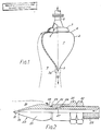
- a first form of jetting nozzle has a first plenum chamber 1, with a substantially heart shaped outer surface 2 providing a fluidic surface.
- the first plenum chamber 1 opens into a nozzle exit 3.
- the wider end 4 of the heart shaped surface 2 are inlets 5 for introduction of high pressure fluid from pipe 6.
- the pipe 6 terminates in a bell 7 adjacent the wide end 4 of surface 2, the bell 7 enclosing the apertures 5 and defining a second plenum 8.
- the end of bell 7 is spaced from end 6 to allow a sidestream of fluid to pass radially outwardly.
- This sidestream of fluid forms a low velocity outer jet 9 which is constrained by the shape of surface 2 to flow in close contact thereto so as to surround high velocity jet 10 issuing from nozzle exit 3.
- the nozzle exit may be provided with a valved outlet 3a to adjust or close off the high velocity jet 10.
- the bell 7 may be mounted so that it can be moved relative to end surface 5 of plenum 1 to adjust or close off low velocity jet 9.
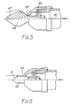
- Fig.6 could, of course, be modified to provide a jetting nozzle according to the first aspect of the invention by forming converter device 52 as a hollow body with a plenum chamber and means for introduction and exit of fluid, as described in connection with Figs.1 to 4.
- an air shroud can completely eliminate shear stress between the cutting jet and the surrounding fluid, thus preventing degradation. Under water, a water shroud will reduce degradation.
- the spent abrasive, rust, old paint and scale may be removed from the pipe by plugging a unit into one end and using a modest quantity of compressed air delivered through a small and manageable hose to generate a high volume flow.
- Anchorage (Outer jet only, of water, or inner and outer jets, both of water.)
- a straight metal tube having a unit on the lower end and connected at the upper end will dig itself into an underwater deposit. This will be more rapid if the deposit is permeable, non-cohesive and does not contain stones. Having been lowered to the required depth, perhaps several metres, the water supply may be disconnected. By virtue of a combination of the weight and passive pressure of overlying material then enlargement at the bottom, represented by the unit, prevents withdrawal. On reconnection of the supply, the material lying against the fluidic surface prevents re-establishment of the original flow pattern and the jet emerges radially, creating a cavity around and above the device, facilitating withdrawal. This has extensive application subsea.
- Water jets are used by divers and remotely-operated submersible vehicles for dispersion of sediment. To eliminate recoil, an equal and opposite jet is arranged. This jet has a velocity equal to that of the principal jet and is thus potentially dangerous to diver and vehicle alike. The velocity of the balancing jet can be reduced without affecting its effectiveness by fitting the device.
- the developing jet is extremely turbulent and the motive fluid (fuel) is quickly mixed intimately with the ambient fluid (air) to form an efficient mixture for combustion.
Landscapes
- Nozzles (AREA)
Applications Claiming Priority (2)
| Application Number | Priority Date | Filing Date | Title |
|---|---|---|---|
| GB8726688 | 1987-11-13 | ||
| GB878726688A GB8726688D0 (en) | 1987-11-13 | 1987-11-13 | Jetting nozzle |
Publications (2)
| Publication Number | Publication Date |
|---|---|
| EP0317238A2 true EP0317238A2 (de) | 1989-05-24 |
| EP0317238A3 EP0317238A3 (de) | 1990-05-16 |
Family
ID=10626951
Family Applications (1)
| Application Number | Title | Priority Date | Filing Date |
|---|---|---|---|
| EP88310727A Withdrawn EP0317238A3 (de) | 1987-11-13 | 1988-11-14 | Strahldüse |
Country Status (4)
| Country | Link |
|---|---|
| US (1) | US5056718A (de) |
| EP (1) | EP0317238A3 (de) |
| GB (1) | GB8726688D0 (de) |
| ZA (1) | ZA888492B (de) |
Cited By (4)
| Publication number | Priority date | Publication date | Assignee | Title |
|---|---|---|---|---|
| EP0438213A3 (en) * | 1990-01-16 | 1992-01-08 | The Babcock & Wilcox Company | Airfoil lance apparatus |
| EP0901830A3 (de) * | 1997-09-11 | 2000-12-20 | WAP Reinigungssysteme GmbH & Co. | Hochdruckdüse mit Breitstrahl |
| WO2006084085A1 (en) * | 2005-02-04 | 2006-08-10 | Ismailov Murad M | Liquid spray system and nozzle with improved spray generation |
| EP2669021A4 (de) * | 2011-01-26 | 2016-08-24 | Jfe Steel Corp | Düse zum entzundern einer stahlplatte, vorrichtung zum entzundern einer stahlplatte und verfahren zum entzundern einer stahlplatte |
Families Citing this family (14)
| Publication number | Priority date | Publication date | Assignee | Title |
|---|---|---|---|---|
| US6587535B1 (en) * | 2001-07-10 | 2003-07-01 | General Electric Company | Jet pump slip joint labyrinth seal method |
| DE10163896B4 (de) * | 2001-12-22 | 2005-02-17 | Daimlerchrysler Ag | Windkanalkurzdüse mit Grenzschichtabschälung |
| DE102010051227A1 (de) | 2010-11-12 | 2012-05-16 | Dental Care Innovation Gmbh | Düse zur Abstrahlung von flüssigen Reinigungsmitteln mit darin dispergierten abrasiven Partikeln |
| KR101804834B1 (ko) * | 2011-05-16 | 2017-12-05 | 신닛떼쯔 수미킨 엔지니어링 가부시끼가이샤 | 압연 롤의 세정 장치 및 세정 방법 |
| US9061328B2 (en) * | 2012-08-03 | 2015-06-23 | William R. Detyens, JR. | Method for cleaning the interior surface of hollow articles |
| US20140252138A1 (en) * | 2013-03-05 | 2014-09-11 | Generac Power Systems, Inc. | Pressure Washer Adjustable Nozzle Assembly |
| WO2016161498A1 (en) * | 2015-04-09 | 2016-10-13 | Nex Flow Air Products Corp. | Blowing nozzle |
| USD860451S1 (en) | 2016-06-02 | 2019-09-17 | Intarcia Therapeutics, Inc. | Implant removal tool |
| US10471623B2 (en) | 2016-10-18 | 2019-11-12 | Hmcc Acquireco2, Llc | Waterjet cutting system with variable liquid level |
| USD825741S1 (en) | 2016-12-15 | 2018-08-14 | Water Pik, Inc. | Oral irrigator handle |
| WO2018170417A1 (en) | 2017-03-16 | 2018-09-20 | Water Pik, Inc. | Oral irrigator handle for use with oral agent |
| US10478945B2 (en) | 2017-06-14 | 2019-11-19 | Hmcc Acquireco2, Llc | Abrasive recovery assembly for a waterjet cutting system |
| DE112018004300T5 (de) * | 2017-09-29 | 2020-05-14 | Husqvarna Ab | Eine einstellbare Düse für eine Gebläse |
| CN108591135A (zh) * | 2018-06-11 | 2018-09-28 | 南华大学 | 锥形空气诱导器 |
Family Cites Families (17)
| Publication number | Priority date | Publication date | Assignee | Title |
|---|---|---|---|---|
| US573721A (en) * | 1896-12-22 | Shelby compton administrator of said swift | ||
| US1734580A (en) * | 1926-09-20 | 1929-11-05 | Creamery Package Mfg Co | Spraying device |
| US2145865A (en) * | 1935-12-05 | 1939-02-07 | Walter S Diehl | Nozzle for fire extinguishing apparatus |
| GB535451A (en) * | 1940-02-07 | 1941-04-09 | Walter Benn | Improvements in or relating to water sprayers |
| US3117726A (en) * | 1960-01-05 | 1964-01-14 | Schoberg Borje Lennart | Detachable apparatus for cleaning hollows by blowing |
| US3073534A (en) * | 1960-05-27 | 1963-01-15 | Goodyear Aircraft Corp | Nozzle for spraying a mixture of fibers and resin |
| FR2121907A5 (de) * | 1971-01-11 | 1972-08-25 | Skm Sa | |
| US3892361A (en) * | 1974-04-18 | 1975-07-01 | Src Lab | Two stage nozzle |
| US3984054A (en) * | 1974-08-26 | 1976-10-05 | Barry Wright Corporation | Nozzle |
| GB1503837A (en) * | 1975-02-21 | 1978-03-15 | Furutsutsumi Y | Apparatus for removing dust having device for producing air curtain |
| US4095747A (en) * | 1976-05-17 | 1978-06-20 | Specialty Manufacturing Company | High pressure coaxial flow nozzles |
| US4154405A (en) * | 1976-07-12 | 1979-05-15 | Salen & Wicander Aktiebolag | Nozzle for delivering a transversally contained jet of liquid |
| DE3007290A1 (de) * | 1980-02-27 | 1981-09-03 | Wolfgang 4800 Bielefeld Suttner | Duesenkopf |
| CA1128582A (en) * | 1980-04-10 | 1982-07-27 | Geoffrey W. Vickers | Cavitation nozzle assembly |
| JPS57502220A (de) * | 1981-01-23 | 1982-12-16 | ||
| US4473186A (en) * | 1982-04-12 | 1984-09-25 | Morton Alperin | Method and apparatus for spraying |
| US4826084A (en) * | 1986-09-26 | 1989-05-02 | Wallace Norman R | Sheathed jet fluid dispersing apparatus |
-
1987
- 1987-11-13 GB GB878726688A patent/GB8726688D0/en active Pending
-
1988
- 1988-11-14 ZA ZA888492A patent/ZA888492B/xx unknown
- 1988-11-14 US US07/270,043 patent/US5056718A/en not_active Expired - Lifetime
- 1988-11-14 EP EP88310727A patent/EP0317238A3/de not_active Withdrawn
Cited By (4)
| Publication number | Priority date | Publication date | Assignee | Title |
|---|---|---|---|---|
| EP0438213A3 (en) * | 1990-01-16 | 1992-01-08 | The Babcock & Wilcox Company | Airfoil lance apparatus |
| EP0901830A3 (de) * | 1997-09-11 | 2000-12-20 | WAP Reinigungssysteme GmbH & Co. | Hochdruckdüse mit Breitstrahl |
| WO2006084085A1 (en) * | 2005-02-04 | 2006-08-10 | Ismailov Murad M | Liquid spray system and nozzle with improved spray generation |
| EP2669021A4 (de) * | 2011-01-26 | 2016-08-24 | Jfe Steel Corp | Düse zum entzundern einer stahlplatte, vorrichtung zum entzundern einer stahlplatte und verfahren zum entzundern einer stahlplatte |
Also Published As
| Publication number | Publication date |
|---|---|
| GB8726688D0 (en) | 1987-12-16 |
| ZA888492B (en) | 1989-08-30 |
| US5056718A (en) | 1991-10-15 |
| EP0317238A3 (de) | 1990-05-16 |
Similar Documents
| Publication | Publication Date | Title |
|---|---|---|
| US5056718A (en) | Jetting nozzle | |
| CA1128582A (en) | Cavitation nozzle assembly | |
| EP0124107B1 (de) | Flüssigkeitsstrahlapparat und Verfahren zum Reinigen von Rohrkomponenten | |
| US4193635A (en) | Controlled cavitation erosion process and system | |
| US4880447A (en) | Method and apparatus for steam flow venting incorporating air educting means | |
| AU622841B2 (en) | Abrasive cleaning or cutting | |
| US4534427A (en) | Abrasive containing fluid jet drilling apparatus and process | |
| US6945859B2 (en) | Apparatus for fluid jet formation | |
| EP2529843B1 (de) | Rückflussdüse zur Erzeugung einer Kavitation oder Impulsstrahlen | |
| NO316114B1 (no) | Fremgangsmåte og anordning for å lage en höyhastighetspartikkelström | |
| EP0110989B1 (de) | Vorrichtung zur herabsetzung der reibung zwischen eis und schiffshaut und strahlpumpe dafür | |
| EP0580573B1 (de) | Verbesserte vorrichtung für unterwasserausgrabung | |
| JP3320105B2 (ja) | キヤビテーシヨン噴流用ノズル | |
| CA3042001C (en) | Jet pump | |
| CN115609492A (zh) | 一种空气-磨料-水复合淹没射流喷嘴、系统及方法 | |
| GB2212074A (en) | Jetting nozzle | |
| EP4132664B1 (de) | Feuerlöscheinrichtung mit feuerlöschdüse | |
| CA2707018A1 (en) | Liquid separating device for the separation of a liquid mixture | |
| KR100836638B1 (ko) | 캐비테이션 감소를 위한 공기 방출 시스템 | |
| RU2072454C1 (ru) | Жидкостно-газовый эжектор | |
| US5098164A (en) | Abrasive jet manifold for a borehole miner | |
| EA009894B1 (ru) | Газосепаратор | |
| SU1708436A1 (ru) | Кавитатор | |
| SU1743617A1 (ru) | Установка дл тушени пожаров | |
| JPH054199A (ja) | 切削・切断方法とその装置 |
Legal Events
| Date | Code | Title | Description |
|---|---|---|---|
| PUAI | Public reference made under article 153(3) epc to a published international application that has entered the european phase |
Free format text: ORIGINAL CODE: 0009012 |
|
| AK | Designated contracting states |
Kind code of ref document: A2 Designated state(s): BE DE FR NL SE |
|
| PUAL | Search report despatched |
Free format text: ORIGINAL CODE: 0009013 |
|
| AK | Designated contracting states |
Kind code of ref document: A3 Designated state(s): BE DE FR NL SE |
|
| 17P | Request for examination filed |
Effective date: 19901004 |
|
| 17Q | First examination report despatched |
Effective date: 19910604 |
|
| STAA | Information on the status of an ep patent application or granted ep patent |
Free format text: STATUS: THE APPLICATION IS DEEMED TO BE WITHDRAWN |
|
| 18D | Application deemed to be withdrawn |
Effective date: 19940817 |