EP0317302A2 - Système de freinage de véhicule - Google Patents
Système de freinage de véhicule Download PDFInfo
- Publication number
- EP0317302A2 EP0317302A2 EP88310837A EP88310837A EP0317302A2 EP 0317302 A2 EP0317302 A2 EP 0317302A2 EP 88310837 A EP88310837 A EP 88310837A EP 88310837 A EP88310837 A EP 88310837A EP 0317302 A2 EP0317302 A2 EP 0317302A2
- Authority
- EP
- European Patent Office
- Prior art keywords
- braking system
- motor
- rings
- control circuit
- brake
- Prior art date
- Legal status (The legal status is an assumption and is not a legal conclusion. Google has not performed a legal analysis and makes no representation as to the accuracy of the status listed.)
- Withdrawn
Links
Images


Classifications
-
- F—MECHANICAL ENGINEERING; LIGHTING; HEATING; WEAPONS; BLASTING
- F16—ENGINEERING ELEMENTS AND UNITS; GENERAL MEASURES FOR PRODUCING AND MAINTAINING EFFECTIVE FUNCTIONING OF MACHINES OR INSTALLATIONS; THERMAL INSULATION IN GENERAL
- F16D—COUPLINGS FOR TRANSMITTING ROTATION; CLUTCHES; BRAKES
- F16D65/00—Parts or details
- F16D65/14—Actuating mechanisms for brakes; Means for initiating operation at a predetermined position
- F16D65/28—Actuating mechanisms for brakes; Means for initiating operation at a predetermined position arranged apart from the brake
-
- B—PERFORMING OPERATIONS; TRANSPORTING
- B60—VEHICLES IN GENERAL
- B60T—VEHICLE BRAKE CONTROL SYSTEMS OR PARTS THEREOF; BRAKE CONTROL SYSTEMS OR PARTS THEREOF, IN GENERAL; ARRANGEMENT OF BRAKING ELEMENTS ON VEHICLES IN GENERAL; PORTABLE DEVICES FOR PREVENTING UNWANTED MOVEMENT OF VEHICLES; VEHICLE MODIFICATIONS TO FACILITATE COOLING OF BRAKES
- B60T8/00—Arrangements for adjusting wheel-braking force to meet varying vehicular or ground-surface conditions, e.g. limiting or varying distribution of braking force
- B60T8/32—Arrangements for adjusting wheel-braking force to meet varying vehicular or ground-surface conditions, e.g. limiting or varying distribution of braking force responsive to a speed condition, e.g. acceleration or deceleration
- B60T8/34—Arrangements for adjusting wheel-braking force to meet varying vehicular or ground-surface conditions, e.g. limiting or varying distribution of braking force responsive to a speed condition, e.g. acceleration or deceleration having a fluid pressure regulator responsive to a speed condition
- B60T8/42—Arrangements for adjusting wheel-braking force to meet varying vehicular or ground-surface conditions, e.g. limiting or varying distribution of braking force responsive to a speed condition, e.g. acceleration or deceleration having a fluid pressure regulator responsive to a speed condition having expanding chambers for controlling pressure, i.e. closed systems
- B60T8/4208—Debooster systems
- B60T8/4266—Debooster systems having an electro-mechanically actuated expansion unit, e.g. solenoid, electric motor, piezo stack
-
- F—MECHANICAL ENGINEERING; LIGHTING; HEATING; WEAPONS; BLASTING
- F16—ENGINEERING ELEMENTS AND UNITS; GENERAL MEASURES FOR PRODUCING AND MAINTAINING EFFECTIVE FUNCTIONING OF MACHINES OR INSTALLATIONS; THERMAL INSULATION IN GENERAL
- F16D—COUPLINGS FOR TRANSMITTING ROTATION; CLUTCHES; BRAKES
- F16D66/00—Arrangements for monitoring working conditions, e.g. wear, temperature
- F16D2066/003—Position, angle or speed
-
- F—MECHANICAL ENGINEERING; LIGHTING; HEATING; WEAPONS; BLASTING
- F16—ENGINEERING ELEMENTS AND UNITS; GENERAL MEASURES FOR PRODUCING AND MAINTAINING EFFECTIVE FUNCTIONING OF MACHINES OR INSTALLATIONS; THERMAL INSULATION IN GENERAL
- F16D—COUPLINGS FOR TRANSMITTING ROTATION; CLUTCHES; BRAKES
- F16D66/00—Arrangements for monitoring working conditions, e.g. wear, temperature
- F16D2066/005—Force, torque, stress or strain
-
- F—MECHANICAL ENGINEERING; LIGHTING; HEATING; WEAPONS; BLASTING
- F16—ENGINEERING ELEMENTS AND UNITS; GENERAL MEASURES FOR PRODUCING AND MAINTAINING EFFECTIVE FUNCTIONING OF MACHINES OR INSTALLATIONS; THERMAL INSULATION IN GENERAL
- F16D—COUPLINGS FOR TRANSMITTING ROTATION; CLUTCHES; BRAKES
- F16D2121/00—Type of actuator operation force
- F16D2121/18—Electric or magnetic
- F16D2121/24—Electric or magnetic using motors
-
- F—MECHANICAL ENGINEERING; LIGHTING; HEATING; WEAPONS; BLASTING
- F16—ENGINEERING ELEMENTS AND UNITS; GENERAL MEASURES FOR PRODUCING AND MAINTAINING EFFECTIVE FUNCTIONING OF MACHINES OR INSTALLATIONS; THERMAL INSULATION IN GENERAL
- F16D—COUPLINGS FOR TRANSMITTING ROTATION; CLUTCHES; BRAKES
- F16D2125/00—Components of actuators
- F16D2125/02—Fluid-pressure mechanisms
- F16D2125/10—Plural pistons interacting by fluid pressure, e.g. hydraulic force amplifiers using different sized pistons
-
- F—MECHANICAL ENGINEERING; LIGHTING; HEATING; WEAPONS; BLASTING
- F16—ENGINEERING ELEMENTS AND UNITS; GENERAL MEASURES FOR PRODUCING AND MAINTAINING EFFECTIVE FUNCTIONING OF MACHINES OR INSTALLATIONS; THERMAL INSULATION IN GENERAL
- F16D—COUPLINGS FOR TRANSMITTING ROTATION; CLUTCHES; BRAKES
- F16D2125/00—Components of actuators
- F16D2125/18—Mechanical mechanisms
- F16D2125/20—Mechanical mechanisms converting rotation to linear movement or vice versa
- F16D2125/34—Mechanical mechanisms converting rotation to linear movement or vice versa acting in the direction of the axis of rotation
- F16D2125/40—Screw-and-nut
-
- F—MECHANICAL ENGINEERING; LIGHTING; HEATING; WEAPONS; BLASTING
- F16—ENGINEERING ELEMENTS AND UNITS; GENERAL MEASURES FOR PRODUCING AND MAINTAINING EFFECTIVE FUNCTIONING OF MACHINES OR INSTALLATIONS; THERMAL INSULATION IN GENERAL
- F16D—COUPLINGS FOR TRANSMITTING ROTATION; CLUTCHES; BRAKES
- F16D2127/00—Auxiliary mechanisms
- F16D2127/007—Auxiliary mechanisms for non-linear operation
-
- F—MECHANICAL ENGINEERING; LIGHTING; HEATING; WEAPONS; BLASTING
- F16—ENGINEERING ELEMENTS AND UNITS; GENERAL MEASURES FOR PRODUCING AND MAINTAINING EFFECTIVE FUNCTIONING OF MACHINES OR INSTALLATIONS; THERMAL INSULATION IN GENERAL
- F16D—COUPLINGS FOR TRANSMITTING ROTATION; CLUTCHES; BRAKES
- F16D2127/00—Auxiliary mechanisms
- F16D2127/06—Locking mechanisms, e.g. acting on actuators, on release mechanisms or on force transmission mechanisms
Definitions
- This invention relates to a vehicle braking system.
- a braking system which includes an electric motor for controlling the application of a friction element to a rotating part, characterised in that the motor has a rotor which is capable of being brought to rest at any one of a plurality of distinct positions and in that the motor is controlled by a control circuit which causes an output member driven by the motor to be positioned in accordance with a variable demand signal.
- the motor will generally be a stepper motor having a rotor which is capable of being brought to rest at any one of a plurality of distinct step positions.
- the motor is preferably controlled by a drive circuit which causes the rotor to be turned to the next step position for each pulse received at an input of the drive circuit.
- a particularly suitable type of stepper motor is the so-called switched reluctance stepper motor, which has a plurality of windings, the drive circuit operating to switch current in each of such windings in several different combinations.
- the motor may include a shaft position encoder which is used to enable the drive circuit to determine what combination of windings should be energised to enable the rotor to be turned to the next step position in either direction.
- control circuit may include an adaptive loop for sensing the effect of brake application operations and adjusting the value of at least one parameter of the control circuit to optimise such effect.
- the control circuit may, indeed, receive signals from several different feedback signal generators sensing different variable conditions and adjust the values of several parameters accordingly.
- control circuit may be arranged to provide automatic adjustment of a datum position of the friction elements to compensate automatically for wear thereof.
- a transducer may be provided to measure the brake load, e.g. where braking forces are transmitted from an hydraulic drive cylinder driven by the stepper motor to one or more hydraulic brake-applying cylinders, the pressure developed in the driven cylinder will be indicative of the load. By sensing this pressure and resetting a position count held by the control circuit when the pressure is at a threshold value (or within a threshold range) such adjustment can be obtained.
- the braking system may comprise an antilock braking system having a debooster as the output member, with the motor and control circuit arranged to deboost the braking system so as to reduce the risk of brake locking.
- Switched reluctance motors are excellent for this purpose, since they can be operated open loop, that is without any position feedback, each pulse supplied to the drive circuit for the motor causing the rotor to turn through one precisely defined step.
- To hold the rotor in a specific position current must be continuously supplied to the windings and this is wasteful since the anti-skid system is called into use for only a small proportion of the time for which the vehicle is in use.
- the drive between the motor and the deboost device could, of course, be made non-reversible in a number of ways, but this would result in the mechanical efficiency of the device being reduced and may give rise to the need for complex constructions including wearing parts such as ratchets or friction brakes.
- an auxiliary magnetic circuit means including permanent magnet means, a first part fixed with respect to a stator of the motor, and a second part fixed with respect to the rotor, the first and second parts being shaped and disposed such that there is a plurality of relative positions thereof at which the reluctance of the magnetic circuit is a minimum.
- auxiliary magnetic circuit means is not limited to use with a debooster but can be applied with advantage in many other circumstances, particularly when loss of motor power must result in a failsafe mode of operation or state.
- the motor may be provided with a pair of toothed rings each having n teeth thereon or an exact multiple of n the rings being attached respectively to the rotor and the stator of the motor in positions such that the teeth on the two rings are aligned whenever the rotor is in one of said n positions.
- One of the two rings may be permanently magnetised in a number of different ways to obtain the desired result.
- a pick-up winding may be incorporated in the ring which is attached to the motor stator, to act as a variable reluctance position or speed transducer.
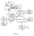
- the braking system shown includes a switched reluctance stepper motor 10 which is used to actuate the brakes of one wheel of a vehicle.
- the stepper motor 10 has an output member 11 which, through a ball-screw and nut arrangement, drives a piston 12 along a cylinder 13.
- This cylinder 13 is connected to several brake applying hydraulic cylinders 14 which can drive friction elements 15 into contact with the interior of a brake drum 16.
- a power-switching circuit 17 is provided to control the direction of current flow in the various stator windings of the motor 10 under the control of signals from a microprocessor-based control circuit 18.
- the stepper motor rotor is moved through one step for each pulse produced at one output 18 a in a direction determined by the signal at another output 18 b .
- An electric power source 24, generally provided by the vehicle battery and charging system, is shown connected to the switching circuit 17.
- a pressure transducer 19 is connected to sense the fluid pressure within the cylinder 13 and this provides a measure of the brake load at any given instant.
- This transducer is interfaced with the circuit 18 via a suitable analog-to-digital converter 20.
- Other variable conditions such as axle load, vehicle deceleration, wheel speeds, and drag on the friction elements, may also be sensed by suitable transducers and fed back to the control circuit 20 via the analog-to-digital converter.
- an axle load sensor 25 and a brake torque sensor 26 are shown connected in this way.
- the control circuit 18 also receives a brake demand signal from a demand signal generator 21 operated by the brake pedal 22 of the vehicle.
- the control circuit operates by positioning the rotor of the stepper motor in accordance with the demand signal from the demand signal generator.
- the control circuit 19 ensures that no slip or stall of the motor 10 occurs thereby ensuring that the value of a position count held within the circuit 18 is always exactly representative of the actual position of the motor rotor.
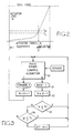
- the main brake control algorithm is shown in block 30 and this will not be described in detail herein.
- the position counter N is decremented by one (32) and the value W held by the control circuit 18 and representing the most recently input value of the output of the transducer 19 is tested (33 and 34) to establish whether it is between two predetermined values T H and T L . If it is, then the value of N is set to a datum value C, before the program returns to the main algorithm. Thereafter the algorithm 30 causes a fixed number of pulses to be supplied to back the brakes off by a fixed clearance distance.
- the values T H and T L represent load values just higher than a "knee" in the travel/load graph. This knee occurs during brake application, as the friction pads start to engage the drum, and its position in the travel/load characteristic varies as a function of wear of the brake friction material. Thus adjustment of the brakes to compensate for wear is made entirely within the operating program of the control circuit.
- FIG 1 shows a driver warning device 27, such as a warning light or alarm sounder, connected to the controller.
- a driver warning device 27 may be actuated by the controller 18 to warn the driver of a potentially dangerous state, for instance when the wear of the brake friction material is greater than a threshold value.
- the controller monitors the performance of the braking system, for instance by comparing the brake torque sensed by the sensor 26 with the hydraulic pressure sensed by the transducer 19, the device 27 may be actuated to warn the driver of brake fade, for instance during an alpine decent.
- the brake pedal 22 merely controls the demand signal generator 21 and provides no fade-dependent "feel" or physical feedback to the foot of the driver.
- the system shown in Figure 1 may also be used for a parking brake of a vehicle by supplying a further demand signal in response to operation of the parking brake.
- the system pressure is monitored by the transducer 19 so that any pressure variation, due to expansion or contraction of mechanical components, for example, or of the hydraulic fluid, can be corrected by the controller 18 operating the motor 10 through the required number of increments to restore the pressure to the required level.
- This enables a very sensitive response to be obtained which permits accurate control of the braking pressure during both dynamic and static braking, enabling an hydraulic system to be employed for parking purposes.
- the system is only active when the parking brake is applied, and does not allow the motor 10 to turn thereafter.
- the system is deenergised when the vehicle is left unattended with the motor 10 unable to turn, so as to avoid the possibility that a system failure would cause the motor 10 to release the hydraulic pressure and thus the brakes.
- Figure 4 shows an alternative type of stepper motor arrangement which may be used in place of the motor 10 and the ball-screw and nut arrangement of Figure 1 for driving the piston 12.
- the stepper motor comprises a stator 40 with an associated winding 41 and a rotor 42 contained within the stator and mounted for rotation therein.
- the rotor has an internal thread 43 and balls 44 are interengaged between this thread and a corresponding thread 45 on a linearly displaceable plunger 46 contained within the rotor. The plunger moves the piston 12 to vary the volume within the cylinder 13.
- stepper motor is beneficial since, provided certain load/speed restrictions are observed by the controller (not shown), the plunger positioning control can be run open loop (i.e. no plunger position transducer is required).
- the preferred stepper motor does not include any permanent magnetic parts, and the drive connection between the rotor 42 and the plunger 46 is a reversible, low-friction connection, there is a risk of unwanted displacement of the plunger, for instance if the stepper motor holding current were to be interrupted. Means are therefore provided to provide holding torque even when the power is cut off.
- This means comprises a pair of magnetic detent rings 50, 51 attached to the stator 40 and the rotor 42, respectively. As shown in Figure 5, these rings have internal and external teeth respectively, and one of the rings (in this case the outer ring 50) is permanently magnetised such that alternate teeth are of opposite polarity. It will be understood by those skilled in the art that, with the arrangement described above, there will be a plurality of equi-angularly spaced positions of the inner ring 51 relative to the outer ring 50, at each of which the reluctance of the magnetic circuit constituted by the two rings is a minimum. The number of teeth on each ring is an exact multiple of the number of step positions of the stepper motor and the rings 50, 51 are mounted so that the minimum reluctance positions coincide with the step positions.
- holding torque is provided by the magnetic detent means in each step position of the rotor 42 to prevent the rotor from turning in the absence of a correct power pulse.
- the torque characteristic of the stepper motor is, of course, altered by the effect of the magnetic detent means.
- the energy used to move the inner ring 51 out of each minimum reluctance position is largely recovered on arrival at the next such position.
- the holding torque is insignificant when the rotor is actually in rotation.
- FIG. 6 An alternative magnetisation of the rings 150, 151 is shown in Figure 6.
- the inner ring 151 which is magnetised and magnetisation has been carried out in a manner to make all the teeth on one side of a diametral plane north poles and all those on the other side south poles.
- the teeth of the: inner ring 261 are divided into a plurality of groups (in the case shown four groups of three teeth) separated by a missing tooth. Alternate groups of teeth are of opposite polarity. This arrangement suffers from less magnetic leakage than the Figure 5 arrangement, but suffers lower flux in the rings than that shown in Figure 6, where the flux in the portions of the outer ring in the neighbourhood of the changeover in polarity of the poles is higher than the flux elsewhere.
- Each ring consists of an annular permanent magnet polarised axially and a pair of toothed soft iron rings sandwiching the permanent magnet ring between them. As shown, the permanent magnets in the two rings are effectively in "series" in the magnetic circuit formed by the rings.
- the outer ring 450 includes a toothed soft iron ring 450 a sandwiched between two identical radially magnetised annular permanent magnets 450 b .
- the inner ring 451 is a toothed soft iron ring which lies between the two permanent magnets. The magnets in this case are effectively in parallel in the magnetic circuit.
- a pick-up winding (not shown) may be incorporated in the magnetic circuit in such a manner as to have electrical signals induced in it by the changes in flux in the magnetic circuit during rotation.
- the winding would be connected to a suitable buffer circuit of known form for converting the induced signals into a pulse train, the frequency of which is proportional to the speed of rotation of the rotor.
- FIG 10 shows a vehicle antilock braking system in which a debooster 500 is provided in an hydraulic brake actuation system between a master cylinder 501 and vehicle brakes 502.
- the debooster 500 will be described in detail hereinafter with reference to Figure 11, but includes a stepper motor connected to the output of a switching circuit 503 which is controlled by a controller 504.
- the controller has an input which receives signals via an interface 505 from wheel sensors 506 which monitor the rotational speed of each vehicle wheel.
- the controller 504 is preferably based on a microprocessor system controlled by software.
- the antilock braking system operates, for instance, by reducing by means of the debooster 500 the hydraulic pressure to the brakes 502 when the controller 504 determines, from the wheel speed measurements performed by the sensors 506, that one of the wheels is decelerating too quickly for proper rolling contact with the ground to be maintained.
- the controller 504 then causes the debooster 500 to restore the hydraulic pressure until wheel deceleration is again determined to be too quick, the process being rapidly repeated as necessary. Further details of the arrangement and operation of the antilock braking system are not necessary for a full description and understanding of embodiment of Figure 10.
- Figure 10 illustrates the system in isolation, it may be embodied as part of a complete vehicle braking system, such as an adaptive brake-by-wire system, for instance in conjunction with the embodiment of Figure 1.
- the debooster 500 includes a stepper motor with a stator 40 and associated winding 41 and a rotor 42, cooperating threads 43, 45 and balls 44, plunger 46, and magnetic detent rings 50, 51.
- the construction and arrangement of these parts is the same as the corresponding parts in Figure 4 and will not be described further.
- the debooster has connections 62 and 63 for connection to hydraulic lines leading to the master cylinder 501 and to slave cylinders of the vehicle brakes 502, respectively.
- the purpose of the plunger 46 is to vary the volume of a chamber 60 within the body of the actuator and the plunger operates in conjunction with a solenoid valve 61.
- the solenoid valve For rapidly releasing the brakes on detection of excessive wheel deceleration, the solenoid valve is closed and the plunger 46 is rapidly displaced to the left as viewed in Figure 11 to increase the volume of the chamber 60 and thereby relieve the brake pressure. Subsequently the brakes are re-applied by displacing the plunger 46 to the right before releasing the solenoid valve.
- stepper motor for this application is beneficial since, provided certain load/speed restrictions are observed by the controller, the plunger positioning control can be run open loop (i.e. no plunger position transducer is required).
- the preferred stepper motor does not include any permanent magnetic parts, and the drive connection between the rotor and the plunger is a reversible, low-friction connection, pressure in the chamber 60 could cause unwanted displacement of the plunger 46 if the stepper motor holding current were to be interrupted.
- the pair of magnetic detent rings 50, 51 attached to the stator and the rotor, respectively, are provided so as to provide holding torque even when power is cut off. These rings may have any of the forms illustrated in Figures 5 to 9.
Landscapes
- Engineering & Computer Science (AREA)
- Mechanical Engineering (AREA)
- General Engineering & Computer Science (AREA)
- Physics & Mathematics (AREA)
- Fluid Mechanics (AREA)
- Transportation (AREA)
- Regulating Braking Force (AREA)
- Braking Systems And Boosters (AREA)
- Braking Arrangements (AREA)
Applications Claiming Priority (6)
| Application Number | Priority Date | Filing Date | Title |
|---|---|---|---|
| GB878727290A GB8727290D0 (en) | 1987-11-20 | 1987-11-20 | Electrically operated actuators |
| GB8727290 | 1987-11-20 | ||
| GB8801089 | 1988-01-19 | ||
| GB888801089A GB8801089D0 (en) | 1988-01-19 | 1988-01-19 | Brake |
| GB888801088A GB8801088D0 (en) | 1988-01-19 | 1988-01-19 | Vehicle braking system |
| GB8801088 | 1988-01-19 |
Publications (2)
| Publication Number | Publication Date |
|---|---|
| EP0317302A2 true EP0317302A2 (fr) | 1989-05-24 |
| EP0317302A3 EP0317302A3 (en) | 1990-06-27 |
Family
ID=27263678
Family Applications (1)
| Application Number | Title | Priority Date | Filing Date |
|---|---|---|---|
| EP88310837A Withdrawn EP0317302A3 (en) | 1987-11-20 | 1988-11-17 | Vehicle braking system |
Country Status (3)
| Country | Link |
|---|---|
| US (1) | US4941553A (fr) |
| EP (1) | EP0317302A3 (fr) |
| JP (1) | JPH01257661A (fr) |
Cited By (5)
| Publication number | Priority date | Publication date | Assignee | Title |
|---|---|---|---|---|
| FR2655933A1 (fr) * | 1989-12-20 | 1991-06-21 | Paugam Rene | Dispositif de freinage hydraulique de vehicules automobiles, permettant l'assistance au freinage et l'antiblocage des roues. |
| WO1997017553A1 (fr) * | 1995-11-04 | 1997-05-15 | Lucas Industries Public Limited Company | Ameliorations apportees a des ensembles freins a disque electriques de vehicules |
| EP1585213A1 (fr) * | 2004-04-06 | 2005-10-12 | Saia-Burgess Murten AG | Dispositif de réglage avec un entraínement |
| EP1666756A1 (fr) | 2004-12-03 | 2006-06-07 | Renault | Contrôle visuel de l'état d'usure d'un tambour de frein |
| US10773701B2 (en) | 2015-09-07 | 2020-09-15 | ZF Automotive UK Limited | Electromechanical actuator |
Families Citing this family (24)
| Publication number | Priority date | Publication date | Assignee | Title |
|---|---|---|---|---|
| FR2655005B1 (fr) * | 1989-11-27 | 1994-04-08 | Andruet Jean Claude | Dispositif de commande du frein de parc pour un vehicule automobile. |
| US5071199A (en) * | 1990-07-26 | 1991-12-10 | General Motors Corp. | Antilock brake system with motor current control |
| US5130593A (en) * | 1990-09-26 | 1992-07-14 | Connell James J | Inductor alternators |
| US5333706A (en) * | 1991-10-22 | 1994-08-02 | Akebono Brake Industry Co., Ltd. | Brake apparatus for a vehicle |
| US5320421A (en) * | 1992-08-10 | 1994-06-14 | General Motors Corporation | Motor driven brake pressure modulator with motor position control |
| US5558409A (en) * | 1994-12-14 | 1996-09-24 | General Motors Corporation | Electrohydraulic braking system |
| US5496102A (en) * | 1995-03-02 | 1996-03-05 | General Motors Corporation | Brake system |
| US5511859A (en) * | 1995-08-25 | 1996-04-30 | General Motors Corporation | Regenerative and friction brake blend control |
| US5861727A (en) * | 1996-04-17 | 1999-01-19 | Dana Corporation | System for controlling operation of a switched reluctance motor between multi-phase operating mode and a reduced phase operating mode |
| JP3837195B2 (ja) * | 1996-12-26 | 2006-10-25 | 曙ブレーキ工業株式会社 | パッドクリアランス調整機構を備えた電動ブレーキとそのパッドクリアランス調整法 |
| US5931547A (en) * | 1997-03-05 | 1999-08-03 | Lerner; Meir Yisochor | Anti-collision system |
| DE19730094A1 (de) * | 1997-07-14 | 1999-01-21 | Itt Mfg Enterprises Inc | System zum Steuern oder Regeln einer elektromechanischen Bremse |
| KR100567637B1 (ko) * | 1997-11-22 | 2006-04-05 | 콘티넨탈 테베스 아게 운트 코. 오하게 | 자동차용 기계·전기식 주차 브레이크의 작동 방법 및 시스템 |
| DE19843123A1 (de) * | 1998-09-21 | 2000-04-20 | Bosch Gmbh Robert | Elektrische Bremse mit Haltebremsfunktion |
| US6684987B2 (en) | 2001-12-28 | 2004-02-03 | Visteon Global Techologies, Inc. | Motor-driven feedback mechanism |
| US6896106B2 (en) * | 2002-10-02 | 2005-05-24 | Arvinmeritor Technology, Llc | Method and assembly for automatic slack adjustment of an electric brake actuator |
| JP2004284444A (ja) * | 2003-03-20 | 2004-10-14 | Advics:Kk | 自動車の制動装置 |
| US7516822B2 (en) * | 2003-08-14 | 2009-04-14 | Arvinmeritor Technology, Llc | Simple electric parking brake actuator motor |
| US20050216160A1 (en) * | 2004-03-23 | 2005-09-29 | Delphi Technologies Inc. | Method for detecting electric-mechanical-brake pad drag and/or calculating actuator efficiency |
| US8260514B2 (en) * | 2004-09-24 | 2012-09-04 | Continental Teves Ag & Co. Ohg | Method for supporting a brake system in case of reduced effectiveness |
| JP4902373B2 (ja) * | 2007-01-30 | 2012-03-21 | 本田技研工業株式会社 | ブレーキ装置およびブレーキ装置の制御方法 |
| US9469284B2 (en) | 2008-04-01 | 2016-10-18 | Donelson Brake Systems, Llc | Method and apparatus for facilitating performance of vehicle braking systems |
| JP5413719B2 (ja) * | 2009-07-31 | 2014-02-12 | 日立オートモティブシステムズ株式会社 | 電動ブレーキ装置 |
| GB201013576D0 (en) * | 2010-08-12 | 2010-09-29 | Microtecnica Actuation Tech Ltd | Electromagnetic brake or clutch and method of operation |
Family Cites Families (11)
| Publication number | Priority date | Publication date | Assignee | Title |
|---|---|---|---|---|
| US2548731A (en) * | 1949-11-18 | 1951-04-10 | Control Instr Co Inc | Reversible step motor |
| DE2128169B2 (de) * | 1971-06-07 | 1973-04-12 | Teldix Gmbh, 6900 Heidelberg | Bremssystem fuer ein fahrzeug, insbesondere kraftfahrzeug |
| DE2208936A1 (de) * | 1972-02-25 | 1973-09-06 | Teldix Gmbh | Bremssystem fuer ein fahrzeug |
| FR2430121A1 (fr) * | 1978-06-28 | 1980-01-25 | Herstal Sa | Machine electrique a reluctance variable |
| DE3410006A1 (de) * | 1984-03-19 | 1985-09-19 | Alfred Teves Gmbh, 6000 Frankfurt | Verfahren zur steuerung einer bremsanlage fuer kraftfahrzeuge und vorrichtung zur durchfuehrung des verfahrens |
| DE3444301A1 (de) * | 1984-12-05 | 1986-06-12 | Alfred Teves Gmbh, 6000 Frankfurt | Elektrisch gesteuerte und angetriebene bremsanlage fuer kraftfahrzeuge |
| DE3518715A1 (de) * | 1985-05-24 | 1986-11-27 | Daimler-Benz Ag, 7000 Stuttgart | Feststell-bremseinrichtung |
| US4793447A (en) * | 1986-12-23 | 1988-12-27 | Allied-Signal Inc. | Electrically operated disc brake |
| GB2205369B (en) * | 1987-06-05 | 1991-11-06 | Teves Gmbh Alfred | Braking pressure modulator |
| GB8801089D0 (en) * | 1988-01-19 | 1988-02-17 | Lucas Ind Plc | Brake |
| EP0317304A3 (en) * | 1987-11-20 | 1990-11-22 | Lucas Industries Public Limited Company | Wheel skid correction device for vehicle braking system |
-
1988
- 1988-11-17 EP EP88310837A patent/EP0317302A3/en not_active Withdrawn
- 1988-11-18 US US07/273,341 patent/US4941553A/en not_active Expired - Fee Related
- 1988-11-18 JP JP63292224A patent/JPH01257661A/ja active Pending
Cited By (6)
| Publication number | Priority date | Publication date | Assignee | Title |
|---|---|---|---|---|
| FR2655933A1 (fr) * | 1989-12-20 | 1991-06-21 | Paugam Rene | Dispositif de freinage hydraulique de vehicules automobiles, permettant l'assistance au freinage et l'antiblocage des roues. |
| WO1997017553A1 (fr) * | 1995-11-04 | 1997-05-15 | Lucas Industries Public Limited Company | Ameliorations apportees a des ensembles freins a disque electriques de vehicules |
| US6230855B1 (en) | 1995-11-04 | 2001-05-15 | Lucas Industries Public Limited Company | Electrically-operated disc brake assemblies for vehicles |
| EP1585213A1 (fr) * | 2004-04-06 | 2005-10-12 | Saia-Burgess Murten AG | Dispositif de réglage avec un entraínement |
| EP1666756A1 (fr) | 2004-12-03 | 2006-06-07 | Renault | Contrôle visuel de l'état d'usure d'un tambour de frein |
| US10773701B2 (en) | 2015-09-07 | 2020-09-15 | ZF Automotive UK Limited | Electromechanical actuator |
Also Published As
| Publication number | Publication date |
|---|---|
| EP0317302A3 (en) | 1990-06-27 |
| JPH01257661A (ja) | 1989-10-13 |
| US4941553A (en) | 1990-07-17 |
Similar Documents
| Publication | Publication Date | Title |
|---|---|---|
| US4941553A (en) | Vehicle braking system | |
| US10351117B2 (en) | Brake unit | |
| US5762407A (en) | Brake system control method and apparatus | |
| US5322352A (en) | Electric vehicle regenerative and friction braking control system | |
| US4758053A (en) | Anti-skid brake control system for automotive vehicle with a feature variable wheel slippage threshold variable depending upon vehicular lateral force | |
| US5975250A (en) | Apparatus and method for detecting the thickness of a brake lining | |
| EP0664273B2 (fr) | Elévateur électrique | |
| JP2725452B2 (ja) | 液圧ブレーキ装置 | |
| EP1234739B1 (fr) | Système et méthode de freinage d'une remorque | |
| EP0317182A2 (fr) | Système de freinage hydraulique | |
| KR100329540B1 (ko) | 전기및기계식제동시스템을구비한자동차 | |
| US20180236876A1 (en) | Vehicle drive system | |
| JPH0443829B2 (fr) | ||
| DE19530676A1 (de) | Elektrofahrzeug mit Traktionssteuerung | |
| EP0853571A1 (fr) | Systeme de commande ou de regulation pour un frein sur roue actionne par un moteur electrique | |
| KR20060023162A (ko) | 전기 기계식 서보 브레이크 | |
| CA2233866C (fr) | Captage d'evenements de performance pour la commande d'une voiturette de golf a moteur electrique | |
| KR0159026B1 (ko) | 앤티-스키드 제어장치 | |
| CN110789505B (zh) | 避免在能电子滑动调节的制动设备的压力介质回路中压力过高的方法和相应的制动设备 | |
| JPH09502681A (ja) | 車両ブレーキ装置の作動圧力決定方法および装置 | |
| GB2472392A (en) | Regenerative braking system having an electric drive means to actuate a mechanical braking device | |
| WO2009138252A1 (fr) | Frein de stationnement électrique activable par pédale de frein | |
| JPH03164360A (ja) | ブレーキシステム | |
| US5468058A (en) | Antilock system with proportional control and pressure memory | |
| GB2366341A (en) | Improving rapid reversal of an electric motor driven brake actuator having a brake lock |
Legal Events
| Date | Code | Title | Description |
|---|---|---|---|
| PUAI | Public reference made under article 153(3) epc to a published international application that has entered the european phase |
Free format text: ORIGINAL CODE: 0009012 |
|
| AK | Designated contracting states |
Kind code of ref document: A2 Designated state(s): DE FR GB |
|
| 17P | Request for examination filed |
Effective date: 19900124 |
|
| PUAL | Search report despatched |
Free format text: ORIGINAL CODE: 0009013 |
|
| AK | Designated contracting states |
Kind code of ref document: A3 Designated state(s): DE FR GB |
|
| 17Q | First examination report despatched |
Effective date: 19910912 |
|
| STAA | Information on the status of an ep patent application or granted ep patent |
Free format text: STATUS: THE APPLICATION IS DEEMED TO BE WITHDRAWN |
|
| 18D | Application deemed to be withdrawn |
Effective date: 19920123 |