EP0317432A1 - Verdichterschaufel mit asymmetrischen Zungen - Google Patents
Verdichterschaufel mit asymmetrischen Zungen Download PDFInfo
- Publication number
- EP0317432A1 EP0317432A1 EP88402882A EP88402882A EP0317432A1 EP 0317432 A1 EP0317432 A1 EP 0317432A1 EP 88402882 A EP88402882 A EP 88402882A EP 88402882 A EP88402882 A EP 88402882A EP 0317432 A1 EP0317432 A1 EP 0317432A1
- Authority
- EP
- European Patent Office
- Prior art keywords
- blade
- wiper
- dawn
- compressor
- movable
- Prior art date
- Legal status (The legal status is an assumption and is not a legal conclusion. Google has not performed a legal analysis and makes no representation as to the accuracy of the status listed.)
- Granted
Links
- 210000002105 tongue Anatomy 0.000 title 1
- 238000007789 sealing Methods 0.000 claims abstract description 4
- 230000006978 adaptation Effects 0.000 description 2
- 238000000576 coating method Methods 0.000 description 1
- 230000006835 compression Effects 0.000 description 1
- 238000007906 compression Methods 0.000 description 1
- 238000013016 damping Methods 0.000 description 1
- 230000003071 parasitic effect Effects 0.000 description 1
- YGSDEFSMJLZEOE-UHFFFAOYSA-N salicylic acid Chemical compound OC(=O)C1=CC=CC=C1O YGSDEFSMJLZEOE-UHFFFAOYSA-N 0.000 description 1
Images
Classifications
-
- F—MECHANICAL ENGINEERING; LIGHTING; HEATING; WEAPONS; BLASTING
- F01—MACHINES OR ENGINES IN GENERAL; ENGINE PLANTS IN GENERAL; STEAM ENGINES
- F01D—NON-POSITIVE DISPLACEMENT MACHINES OR ENGINES, e.g. STEAM TURBINES
- F01D5/00—Blades; Blade-carrying members; Heating, heat-insulating, cooling or antivibration means on the blades or the members
- F01D5/12—Blades
- F01D5/14—Form or construction
- F01D5/20—Specially-shaped blade tips to seal space between tips and stator
-
- Y—GENERAL TAGGING OF NEW TECHNOLOGICAL DEVELOPMENTS; GENERAL TAGGING OF CROSS-SECTIONAL TECHNOLOGIES SPANNING OVER SEVERAL SECTIONS OF THE IPC; TECHNICAL SUBJECTS COVERED BY FORMER USPC CROSS-REFERENCE ART COLLECTIONS [XRACs] AND DIGESTS
- Y02—TECHNOLOGIES OR APPLICATIONS FOR MITIGATION OR ADAPTATION AGAINST CLIMATE CHANGE
- Y02T—CLIMATE CHANGE MITIGATION TECHNOLOGIES RELATED TO TRANSPORTATION
- Y02T50/00—Aeronautics or air transport
- Y02T50/60—Efficient propulsion technologies, e.g. for aircraft
Definitions
- the present invention relates to compressor blades, in particular the movable blades forming the rotor stages of a turbomachine compressor.
- seals and wear seals made up of so-called “abradable” coatings, are placed on the internal surfaces of the casing, opposite the ends of movable blades and, in certain turbomachine applications, the ends movable blades carry profiled elements in the form of teeth and commonly called wipers, which are capable of cooperating with said abradable linings to ensure sealing.
- FR-A 2 465 067 provides for damping of the vibrations of a blade of the blade by providing a slot on the blade body, on the trailing edge side, going from the free end towards the blade heel.
- the object of the invention is rather to avoid the appearance of vibrations by modifying the aerodynamic conditions at the tip of a blade.
- a movable blade according to the invention and meeting these conditions is characterized in that the end wiper is discontinuous and consists of two parts or half wipers arranged, each on one side of the blade, asymmetrically according to a blade end cross-sectional plane.
- a portion of the wiper involves the lower surface of the blade on the leading edge side and the other part, the upper surface of the blade on the trailing edge side, or these respective positions are reversed, or the ends of the half-wipers on the internal side of the blade may or may not have an overlap in front view.
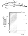
- FIGs 1, 1a and 5 there is shown a blade 1 of a movable stage of the compressor of a turbomachine, according to the invention according to a first embodiment.
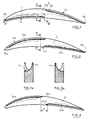
- the free end 2 of the blade 3 of said blade 1 carries a discontinuous wiper 4, consisting of two parts or half wipers 4a and 4b whose arrangement introduces an asymmetry at said blade end 2.
- the first half-wiper 4a is located on the lower surface 1a of the blade 1 and extends from the leading edge 3a of the blade to the vicinity of the median plane perpendicular to the chord of the blade and the second the wiper 4b is located on the upper surface 1b of the blade 1 and extends from the said median plane to the trailing edge 3b of the blade.
- the first half wiper 14a is located on the upper surface 11b of a movable blade 11 and extends from the leading edge 13a of the blade up to the vicinity of the median plane perpendicular to the chord of the blade and the second wiper 14b is located on the lower surface 11a of the blade 11 and extends from said median plane to the trailing edge 13b of the blade.
- FIG. 3 shows a variant of the second embodiment shown in FIGS. 2 and 2a, in which the respective ends 24c and 24d of the half-wipers 24a and 24b, situated on the internal side of the blade 21 reveal a gap d between the end planes perpendicular to the blade edge respectively.
- FIG. 4 shows another variant of the second embodiment shown in FIGS. 2 and 2a, in which the respective ends 34c and 34d of the half-wipers 34a and 34b have an overlapping portion over a length 1.
- the flow conditions at the end dawn 31 are thus modified by the creation of a mini-channel 35, thus modifying the parasitic flows in blade tip and boundary flow conditions.
- FIGS. 3 and 4 which have been applied to the second embodiment according to FIGS. 2 and 2a can similarly be applied to the first embodiment according to FIGS. 1 and 1a.
Landscapes
- Engineering & Computer Science (AREA)
- Mechanical Engineering (AREA)
- General Engineering & Computer Science (AREA)
- Structures Of Non-Positive Displacement Pumps (AREA)
- Turbine Rotor Nozzle Sealing (AREA)
Applications Claiming Priority (2)
| Application Number | Priority Date | Filing Date | Title |
|---|---|---|---|
| FR8715981 | 1987-11-19 | ||
| FR8715981A FR2623569A1 (fr) | 1987-11-19 | 1987-11-19 | Aube de compresseur a lechettes d'extremite dissymetriques |
Publications (2)
| Publication Number | Publication Date |
|---|---|
| EP0317432A1 true EP0317432A1 (de) | 1989-05-24 |
| EP0317432B1 EP0317432B1 (de) | 1992-01-08 |
Family
ID=9356934
Family Applications (1)
| Application Number | Title | Priority Date | Filing Date |
|---|---|---|---|
| EP88402882A Expired - Lifetime EP0317432B1 (de) | 1987-11-19 | 1988-11-17 | Verdichterschaufel mit asymmetrischen Zungen |
Country Status (6)
| Country | Link |
|---|---|
| US (1) | US4875831A (de) |
| EP (1) | EP0317432B1 (de) |
| JP (1) | JPH0689647B2 (de) |
| CA (1) | CA1294558C (de) |
| DE (1) | DE3867606D1 (de) |
| FR (1) | FR2623569A1 (de) |
Cited By (7)
| Publication number | Priority date | Publication date | Assignee | Title |
|---|---|---|---|---|
| FR2711181A1 (fr) * | 1993-10-15 | 1995-04-21 | United Technologies Corp | Procédés et dispositifs aptes à réduire les contraintes sur les pointes des pales de turbine ou de compresseur, ainsi que les moteurs ou compresseurs utilisant de tels procédés et dispositifs. |
| EP0718467A1 (de) * | 1994-12-19 | 1996-06-26 | General Electric Company | Kühlung von Turbinenschaufelspitzen |
| EP0801209A3 (de) * | 1996-04-12 | 1999-07-07 | ROLLS-ROYCE plc | Spitzendichtung für Turbinenlaufschaufeln |
| EP1953344A1 (de) * | 2007-02-05 | 2008-08-06 | Siemens Aktiengesellschaft | Turbinenschaufel |
| FR2962762A1 (fr) * | 2010-07-19 | 2012-01-20 | Snecma | Aube de compresseur dans une turbomachine |
| EP2960434A1 (de) * | 2014-06-25 | 2015-12-30 | Siemens Aktiengesellschaft | Verdichterprofil und zugehörige Verdichterrotorbaugruppe |
| EP3421724A1 (de) * | 2017-06-26 | 2019-01-02 | Siemens Aktiengesellschaft | Kompressorschaufel |
Families Citing this family (19)
| Publication number | Priority date | Publication date | Assignee | Title |
|---|---|---|---|---|
| DE68916040T2 (de) * | 1989-11-15 | 1995-02-02 | Stichting Tech Wetenschapp | Schiffsschraube. |
| US5997251A (en) * | 1997-11-17 | 1999-12-07 | General Electric Company | Ribbed turbine blade tip |
| US6059530A (en) * | 1998-12-21 | 2000-05-09 | General Electric Company | Twin rib turbine blade |
| DE10352253A1 (de) * | 2003-11-08 | 2005-06-09 | Alstom Technology Ltd | Verdichterlaufschaufel |
| GB0400752D0 (en) * | 2004-01-13 | 2004-02-18 | Rolls Royce Plc | Cantilevered stator stage |
| FR2891594A1 (fr) * | 2005-09-30 | 2007-04-06 | Snecma Sa | Aube de compresseur a sommet chanfreine |
| US7513743B2 (en) * | 2006-05-02 | 2009-04-07 | Siemens Energy, Inc. | Turbine blade with wavy squealer tip rail |
| JP4830812B2 (ja) * | 2006-11-24 | 2011-12-07 | 株式会社Ihi | 圧縮機動翼 |
| US8313300B2 (en) * | 2007-06-14 | 2012-11-20 | Christianson Systems, Inc. | Rotor for centrifugal compressor |
| US8092178B2 (en) * | 2008-11-28 | 2012-01-10 | Pratt & Whitney Canada Corp. | Turbine blade for a gas turbine engine |
| EP2282015B1 (de) * | 2009-06-30 | 2013-04-17 | Alstom Technology Ltd | Turbomaschine mit verbesserter Dichtung |
| US8790088B2 (en) * | 2011-04-20 | 2014-07-29 | General Electric Company | Compressor having blade tip features |
| EP2530330B1 (de) * | 2011-06-01 | 2016-05-25 | MTU Aero Engines AG | Laufschaufel für einen Verdichter einer Turbomaschine, Verdichter sowie Turbomaschine |
| DE102014003123A1 (de) * | 2014-03-03 | 2015-09-03 | Mtu Friedrichshafen Gmbh | Verdichter |
| US20160237831A1 (en) * | 2015-02-12 | 2016-08-18 | United Technologies Corporation | Abrasive blade tip with improved wear at high interaction rate |
| US10633983B2 (en) * | 2016-03-07 | 2020-04-28 | General Electric Company | Airfoil tip geometry to reduce blade wear in gas turbine engines |
| CN107061363A (zh) * | 2017-05-22 | 2017-08-18 | 北京航空航天大学 | 一种抑制压气机叶尖泄漏流的叶顶结构形式 |
| EP3477059A1 (de) * | 2017-10-26 | 2019-05-01 | Siemens Aktiengesellschaft | Kompressorschaufel |
| DE102021130682A1 (de) | 2021-11-23 | 2023-05-25 | MTU Aero Engines AG | Schaufelblatt für eine Strömungsmaschine |
Citations (5)
| Publication number | Priority date | Publication date | Assignee | Title |
|---|---|---|---|---|
| GB193777A (en) * | 1922-04-18 | 1923-03-01 | Ljungstroms Angturbin Ab | Improvements in packing means for the blades of steam turbines |
| CH374085A (de) * | 1959-12-29 | 1963-12-31 | Escher Wyss Ag | Schaufel für Dampfturbine, Gasturbine oder Verdichter |
| CH475471A (de) * | 1966-12-20 | 1969-07-15 | Elin Union Ag | Turbinenschaufel |
| DE1937395A1 (de) * | 1969-07-23 | 1971-02-11 | Dettmering Prof Dr Ing Wilhelm | Gitter zur Vermeidung der Sekundaerstroemung |
| GB2075129A (en) * | 1980-05-01 | 1981-11-11 | Gen Electric | Tip cap for a rotor blade and method of replacement |
Family Cites Families (2)
| Publication number | Priority date | Publication date | Assignee | Title |
|---|---|---|---|---|
| US2459850A (en) * | 1945-12-10 | 1949-01-25 | Westinghouse Electric Corp | Turbine apparatus |
| SU779591A1 (ru) * | 1978-12-14 | 1980-11-15 | Ленинградский Ордена Ленина Кораблестроительный Институт | Рабочее колесо турбомашины |
-
1987
- 1987-11-19 FR FR8715981A patent/FR2623569A1/fr active Pending
-
1988
- 1988-11-15 CA CA000583114A patent/CA1294558C/fr not_active Expired - Lifetime
- 1988-11-16 JP JP63289932A patent/JPH0689647B2/ja not_active Expired - Fee Related
- 1988-11-17 EP EP88402882A patent/EP0317432B1/de not_active Expired - Lifetime
- 1988-11-17 DE DE8888402882T patent/DE3867606D1/de not_active Expired - Lifetime
- 1988-11-18 US US07/273,090 patent/US4875831A/en not_active Expired - Lifetime
Patent Citations (5)
| Publication number | Priority date | Publication date | Assignee | Title |
|---|---|---|---|---|
| GB193777A (en) * | 1922-04-18 | 1923-03-01 | Ljungstroms Angturbin Ab | Improvements in packing means for the blades of steam turbines |
| CH374085A (de) * | 1959-12-29 | 1963-12-31 | Escher Wyss Ag | Schaufel für Dampfturbine, Gasturbine oder Verdichter |
| CH475471A (de) * | 1966-12-20 | 1969-07-15 | Elin Union Ag | Turbinenschaufel |
| DE1937395A1 (de) * | 1969-07-23 | 1971-02-11 | Dettmering Prof Dr Ing Wilhelm | Gitter zur Vermeidung der Sekundaerstroemung |
| GB2075129A (en) * | 1980-05-01 | 1981-11-11 | Gen Electric | Tip cap for a rotor blade and method of replacement |
Non-Patent Citations (1)
| Title |
|---|
| SOVIET INVENTIONS ILLUSTRATED, section P/Q, semaine D32, 16 septembre 1981, page 2, no. H4166D/32, Derwent Publications Ltd, Londres, GB; & SU-A-779 591 (LENGD SHIP BUILDING) 15-11-1980 * |
Cited By (13)
| Publication number | Priority date | Publication date | Assignee | Title |
|---|---|---|---|---|
| FR2711181A1 (fr) * | 1993-10-15 | 1995-04-21 | United Technologies Corp | Procédés et dispositifs aptes à réduire les contraintes sur les pointes des pales de turbine ou de compresseur, ainsi que les moteurs ou compresseurs utilisant de tels procédés et dispositifs. |
| EP0718467A1 (de) * | 1994-12-19 | 1996-06-26 | General Electric Company | Kühlung von Turbinenschaufelspitzen |
| EP0801209A3 (de) * | 1996-04-12 | 1999-07-07 | ROLLS-ROYCE plc | Spitzendichtung für Turbinenlaufschaufeln |
| US6142739A (en) * | 1996-04-12 | 2000-11-07 | Rolls-Royce Plc | Turbine rotor blades |
| EP1953344A1 (de) * | 2007-02-05 | 2008-08-06 | Siemens Aktiengesellschaft | Turbinenschaufel |
| FR2962762A1 (fr) * | 2010-07-19 | 2012-01-20 | Snecma | Aube de compresseur dans une turbomachine |
| EP2960434A1 (de) * | 2014-06-25 | 2015-12-30 | Siemens Aktiengesellschaft | Verdichterprofil und zugehörige Verdichterrotorbaugruppe |
| WO2015197328A1 (en) * | 2014-06-25 | 2015-12-30 | Siemens Aktiengesellschaft | Compressor aerofoil and corresponding compressor rotor assembly |
| US10267330B2 (en) | 2014-06-25 | 2019-04-23 | Siemens Aktiengesellschaft | Compressor aerofoil and corresponding compressor rotor assembly |
| EP3421724A1 (de) * | 2017-06-26 | 2019-01-02 | Siemens Aktiengesellschaft | Kompressorschaufel |
| WO2019001980A1 (en) * | 2017-06-26 | 2019-01-03 | Siemens Aktiengesellschaft | DAWN OF COMPRESSOR |
| RU2729590C1 (ru) * | 2017-06-26 | 2020-08-11 | Сименс Акциенгезелльшафт | Перо компрессора |
| US11085308B2 (en) | 2017-06-26 | 2021-08-10 | Siemens Energy Global GmbH & Co. KG | Compressor aerofoil |
Also Published As
| Publication number | Publication date |
|---|---|
| CA1294558C (fr) | 1992-01-21 |
| JPH0689647B2 (ja) | 1994-11-09 |
| DE3867606D1 (de) | 1992-02-20 |
| EP0317432B1 (de) | 1992-01-08 |
| FR2623569A1 (fr) | 1989-05-26 |
| US4875831A (en) | 1989-10-24 |
| JPH01159401A (ja) | 1989-06-22 |
Similar Documents
| Publication | Publication Date | Title |
|---|---|---|
| EP0317432B1 (de) | Verdichterschaufel mit asymmetrischen Zungen | |
| CA2448802C (fr) | Aube de turbine avec lechette d'etancheite | |
| FR2688264A1 (fr) | Redresseur de turbomachine a aubes ayant une face alveolee chargee en materiau composite. | |
| EP0151071B1 (de) | Dichtungssystem zwischen den Schaufelspitzen und dem Gehäuse eines Axialkompressors | |
| EP0291407B1 (de) | Bewegbare Gebläseschaufel mit einer Schneidkante am Ende | |
| FR2694046A1 (fr) | Dispositif d'étanchéité et de rétention pour un rotor entaillé de brochages recevant des pieds d'aubes. | |
| EP1308630B1 (de) | Statorsektor für einen Verdichter eines Turbotriebwerks | |
| FR2831207A1 (fr) | Plates-formes pour aubes d'un ensemble rotatif | |
| KR920006057A (ko) | 가스터빈 및 가스터빈 블레이드와 이 가스터빈 블레이드의 제조방법 | |
| FR2526508A1 (fr) | Joint de culasse pour moteur a combustion interne | |
| FR3085714A1 (fr) | Rotor de turbomachine comportant des moyens limitant les mouvements de l'aube dans le disque de rotor | |
| EP3677752B1 (de) | Verbesserte dichtungsanordnung für eine zwischenschaufelplattform | |
| CA2481883C (fr) | Dispositif d'attache d'une aube mobile sur un disque de rotor de turbine dans une turbomachine | |
| EP0953729B1 (de) | Leitbeschaufelung für eine Turbomaschine | |
| EP1770244A1 (de) | Verdichterschaufel mit angefaster Spitze | |
| CA2860540A1 (fr) | Secteur angulaire de redresseur a amortissement de vibrations par coin pour compresseur de turbomachine | |
| EP1469165B1 (de) | Verminderung des Blattspitzenspiels bei einer Gasturbine | |
| FR2978798A1 (fr) | Secteur angulaire de redresseur de turbomachine a amortissement des modes de vibrations | |
| EP2823150B1 (de) | Schaufel einer turbomaschine mit einem einsatz zum schutz der schaufelspitze | |
| EP1757796A2 (de) | Verdichter mit einer Mehrzahl von Segmenten, welche ein ringformiges Volumen bilden, und die Strömung in einem Triebwerk trennen | |
| FR3015553A1 (fr) | Aube comprenant une echasse, munie d'une seule portion en depression | |
| FR2874402A1 (fr) | Aube de rotor d'un compresseur ou d'une turbine a gaz | |
| FR3084694A1 (fr) | Fixation d'un distributeur a un carter d'une turbomachine | |
| FR2891003A1 (fr) | Aube de turbomachine | |
| EP0388286A1 (de) | Schaufeln mit Hammerköpfen zur verbesserten Winkelpositionierung |
Legal Events
| Date | Code | Title | Description |
|---|---|---|---|
| PUAI | Public reference made under article 153(3) epc to a published international application that has entered the european phase |
Free format text: ORIGINAL CODE: 0009012 |
|
| 17P | Request for examination filed |
Effective date: 19881130 |
|
| AK | Designated contracting states |
Kind code of ref document: A1 Designated state(s): DE FR GB IT SE |
|
| 17Q | First examination report despatched |
Effective date: 19901001 |
|
| RAP1 | Party data changed (applicant data changed or rights of an application transferred) |
Owner name: SOCIETE NATIONALE D'ETUDE ET DE CONSTRUCTION DE MO |
|
| GRAA | (expected) grant |
Free format text: ORIGINAL CODE: 0009210 |
|
| ITF | It: translation for a ep patent filed | ||
| AK | Designated contracting states |
Kind code of ref document: B1 Designated state(s): DE FR GB IT SE |
|
| GBT | Gb: translation of ep patent filed (gb section 77(6)(a)/1977) | ||
| REF | Corresponds to: |
Ref document number: 3867606 Country of ref document: DE Date of ref document: 19920220 |
|
| PLBE | No opposition filed within time limit |
Free format text: ORIGINAL CODE: 0009261 |
|
| STAA | Information on the status of an ep patent application or granted ep patent |
Free format text: STATUS: NO OPPOSITION FILED WITHIN TIME LIMIT |
|
| 26N | No opposition filed | ||
| EAL | Se: european patent in force in sweden |
Ref document number: 88402882.0 |
|
| REG | Reference to a national code |
Ref country code: GB Ref legal event code: IF02 |
|
| REG | Reference to a national code |
Ref country code: FR Ref legal event code: TP Ref country code: FR Ref legal event code: CD |
|
| PGFP | Annual fee paid to national office [announced via postgrant information from national office to epo] |
Ref country code: SE Payment date: 20041025 Year of fee payment: 17 Ref country code: FR Payment date: 20041025 Year of fee payment: 17 |
|
| PGFP | Annual fee paid to national office [announced via postgrant information from national office to epo] |
Ref country code: GB Payment date: 20041026 Year of fee payment: 17 Ref country code: DE Payment date: 20041026 Year of fee payment: 17 |
|
| PG25 | Lapsed in a contracting state [announced via postgrant information from national office to epo] |
Ref country code: IT Free format text: LAPSE BECAUSE OF NON-PAYMENT OF DUE FEES;WARNING: LAPSES OF ITALIAN PATENTS WITH EFFECTIVE DATE BEFORE 2007 MAY HAVE OCCURRED AT ANY TIME BEFORE 2007. THE CORRECT EFFECTIVE DATE MAY BE DIFFERENT FROM THE ONE RECORDED. Effective date: 20051117 Ref country code: GB Free format text: LAPSE BECAUSE OF NON-PAYMENT OF DUE FEES Effective date: 20051117 |
|
| PG25 | Lapsed in a contracting state [announced via postgrant information from national office to epo] |
Ref country code: SE Free format text: LAPSE BECAUSE OF NON-PAYMENT OF DUE FEES Effective date: 20051118 |
|
| REG | Reference to a national code |
Ref country code: FR Ref legal event code: CD |
|
| PG25 | Lapsed in a contracting state [announced via postgrant information from national office to epo] |
Ref country code: DE Free format text: LAPSE BECAUSE OF NON-PAYMENT OF DUE FEES Effective date: 20060601 |
|
| EUG | Se: european patent has lapsed | ||
| GBPC | Gb: european patent ceased through non-payment of renewal fee |
Effective date: 20051117 |
|
| PG25 | Lapsed in a contracting state [announced via postgrant information from national office to epo] |
Ref country code: FR Free format text: LAPSE BECAUSE OF NON-PAYMENT OF DUE FEES Effective date: 20060731 |
|
| REG | Reference to a national code |
Ref country code: FR Ref legal event code: ST Effective date: 20060731 |