EP3677752B1 - Verbesserte dichtungsanordnung für eine zwischenschaufelplattform - Google Patents
Verbesserte dichtungsanordnung für eine zwischenschaufelplattform Download PDFInfo
- Publication number
- EP3677752B1 EP3677752B1 EP19220063.2A EP19220063A EP3677752B1 EP 3677752 B1 EP3677752 B1 EP 3677752B1 EP 19220063 A EP19220063 A EP 19220063A EP 3677752 B1 EP3677752 B1 EP 3677752B1
- Authority
- EP
- European Patent Office
- Prior art keywords
- seal
- platform
- blade
- contact
- structural portion
- Prior art date
- Legal status (The legal status is an assumption and is not a legal conclusion. Google has not performed a legal analysis and makes no representation as to the accuracy of the status listed.)
- Active
Links
Images



Classifications
-
- F—MECHANICAL ENGINEERING; LIGHTING; HEATING; WEAPONS; BLASTING
- F01—MACHINES OR ENGINES IN GENERAL; ENGINE PLANTS IN GENERAL; STEAM ENGINES
- F01D—NON-POSITIVE DISPLACEMENT MACHINES OR ENGINES, e.g. STEAM TURBINES
- F01D11/00—Preventing or minimising internal leakage of working-fluid, e.g. between stages
- F01D11/005—Sealing means between non relatively rotating elements
- F01D11/006—Sealing the gap between rotor blades or blades and rotor
- F01D11/008—Sealing the gap between rotor blades or blades and rotor by spacer elements between the blades, e.g. independent interblade platforms
-
- F—MECHANICAL ENGINEERING; LIGHTING; HEATING; WEAPONS; BLASTING
- F04—POSITIVE - DISPLACEMENT MACHINES FOR LIQUIDS; PUMPS FOR LIQUIDS OR ELASTIC FLUIDS
- F04D—NON-POSITIVE-DISPLACEMENT PUMPS
- F04D29/00—Details, component parts, or accessories
- F04D29/08—Sealings
- F04D29/083—Sealings especially adapted for elastic fluid pumps
-
- F—MECHANICAL ENGINEERING; LIGHTING; HEATING; WEAPONS; BLASTING
- F04—POSITIVE - DISPLACEMENT MACHINES FOR LIQUIDS; PUMPS FOR LIQUIDS OR ELASTIC FLUIDS
- F04D—NON-POSITIVE-DISPLACEMENT PUMPS
- F04D29/00—Details, component parts, or accessories
- F04D29/08—Sealings
- F04D29/16—Sealings between pressure and suction sides
- F04D29/161—Sealings between pressure and suction sides especially adapted for elastic fluid pumps
- F04D29/164—Sealings between pressure and suction sides especially adapted for elastic fluid pumps of an axial flow wheel
-
- F—MECHANICAL ENGINEERING; LIGHTING; HEATING; WEAPONS; BLASTING
- F01—MACHINES OR ENGINES IN GENERAL; ENGINE PLANTS IN GENERAL; STEAM ENGINES
- F01D—NON-POSITIVE DISPLACEMENT MACHINES OR ENGINES, e.g. STEAM TURBINES
- F01D11/00—Preventing or minimising internal leakage of working-fluid, e.g. between stages
- F01D11/005—Sealing means between non relatively rotating elements
- F01D11/006—Sealing the gap between rotor blades or blades and rotor
-
- F—MECHANICAL ENGINEERING; LIGHTING; HEATING; WEAPONS; BLASTING
- F01—MACHINES OR ENGINES IN GENERAL; ENGINE PLANTS IN GENERAL; STEAM ENGINES
- F01D—NON-POSITIVE DISPLACEMENT MACHINES OR ENGINES, e.g. STEAM TURBINES
- F01D5/00—Blades; Blade-carrying members; Heating, heat-insulating, cooling or antivibration means on the blades or the members
- F01D5/02—Blade-carrying members, e.g. rotors
-
- F—MECHANICAL ENGINEERING; LIGHTING; HEATING; WEAPONS; BLASTING
- F04—POSITIVE - DISPLACEMENT MACHINES FOR LIQUIDS; PUMPS FOR LIQUIDS OR ELASTIC FLUIDS
- F04D—NON-POSITIVE-DISPLACEMENT PUMPS
- F04D29/00—Details, component parts, or accessories
- F04D29/26—Rotors specially for elastic fluids
- F04D29/32—Rotors specially for elastic fluids for axial flow pumps
- F04D29/321—Rotors specially for elastic fluids for axial flow pumps for axial flow compressors
- F04D29/322—Blade mountings
-
- F—MECHANICAL ENGINEERING; LIGHTING; HEATING; WEAPONS; BLASTING
- F05—INDEXING SCHEMES RELATING TO ENGINES OR PUMPS IN VARIOUS SUBCLASSES OF CLASSES F01-F04
- F05D—INDEXING SCHEME FOR ASPECTS RELATING TO NON-POSITIVE-DISPLACEMENT MACHINES OR ENGINES, GAS-TURBINES OR JET-PROPULSION PLANTS
- F05D2220/00—Application
- F05D2220/30—Application in turbines
- F05D2220/36—Application in turbines specially adapted for the fan of turbofan engines
-
- F—MECHANICAL ENGINEERING; LIGHTING; HEATING; WEAPONS; BLASTING
- F05—INDEXING SCHEMES RELATING TO ENGINES OR PUMPS IN VARIOUS SUBCLASSES OF CLASSES F01-F04
- F05D—INDEXING SCHEME FOR ASPECTS RELATING TO NON-POSITIVE-DISPLACEMENT MACHINES OR ENGINES, GAS-TURBINES OR JET-PROPULSION PLANTS
- F05D2240/00—Components
- F05D2240/20—Rotors
-
- F—MECHANICAL ENGINEERING; LIGHTING; HEATING; WEAPONS; BLASTING
- F05—INDEXING SCHEMES RELATING TO ENGINES OR PUMPS IN VARIOUS SUBCLASSES OF CLASSES F01-F04
- F05D—INDEXING SCHEME FOR ASPECTS RELATING TO NON-POSITIVE-DISPLACEMENT MACHINES OR ENGINES, GAS-TURBINES OR JET-PROPULSION PLANTS
- F05D2240/00—Components
- F05D2240/55—Seals
-
- F—MECHANICAL ENGINEERING; LIGHTING; HEATING; WEAPONS; BLASTING
- F05—INDEXING SCHEMES RELATING TO ENGINES OR PUMPS IN VARIOUS SUBCLASSES OF CLASSES F01-F04
- F05D—INDEXING SCHEME FOR ASPECTS RELATING TO NON-POSITIVE-DISPLACEMENT MACHINES OR ENGINES, GAS-TURBINES OR JET-PROPULSION PLANTS
- F05D2240/00—Components
- F05D2240/80—Platforms for stationary or moving blades
-
- F—MECHANICAL ENGINEERING; LIGHTING; HEATING; WEAPONS; BLASTING
- F05—INDEXING SCHEMES RELATING TO ENGINES OR PUMPS IN VARIOUS SUBCLASSES OF CLASSES F01-F04
- F05D—INDEXING SCHEME FOR ASPECTS RELATING TO NON-POSITIVE-DISPLACEMENT MACHINES OR ENGINES, GAS-TURBINES OR JET-PROPULSION PLANTS
- F05D2260/00—Function
- F05D2260/30—Retaining components in desired mutual position
- F05D2260/36—Retaining components in desired mutual position by a form fit connection, e.g. by interlocking
-
- F—MECHANICAL ENGINEERING; LIGHTING; HEATING; WEAPONS; BLASTING
- F05—INDEXING SCHEMES RELATING TO ENGINES OR PUMPS IN VARIOUS SUBCLASSES OF CLASSES F01-F04
- F05D—INDEXING SCHEME FOR ASPECTS RELATING TO NON-POSITIVE-DISPLACEMENT MACHINES OR ENGINES, GAS-TURBINES OR JET-PROPULSION PLANTS
- F05D2260/00—Function
- F05D2260/30—Retaining components in desired mutual position
- F05D2260/38—Retaining components in desired mutual position by a spring, i.e. spring loaded or biased towards a certain position
-
- F—MECHANICAL ENGINEERING; LIGHTING; HEATING; WEAPONS; BLASTING
- F05—INDEXING SCHEMES RELATING TO ENGINES OR PUMPS IN VARIOUS SUBCLASSES OF CLASSES F01-F04
- F05D—INDEXING SCHEME FOR ASPECTS RELATING TO NON-POSITIVE-DISPLACEMENT MACHINES OR ENGINES, GAS-TURBINES OR JET-PROPULSION PLANTS
- F05D2300/00—Materials; Properties thereof
- F05D2300/40—Organic materials
- F05D2300/43—Synthetic polymers, e.g. plastics; Rubber
Definitions
- the invention relates to an inter-blade platform seal.
- Such a seal is arranged between a blade and an inter-blade platform distinct from the blade, and aims to limit the circulation of air between the blade and the inter-blade platform.
- Such a seal is used in particular, but not exclusively, in the fans (or “fans” in English) of turbomachines, between the fan blades and the inter-blade platforms.
- the fan blade platforms must fulfill several functions. From an aerodynamic point of view, these platforms have the primary function of delimiting the flow path of the air. In addition, they must also be capable of withstanding high forces while deforming as little as possible and remaining integral with the disk which carries them.
- the platforms have a first part, the vein wall, making it possible to define the air flow vein and to ensure the retention of the platform when the engine is in rotation, and a second part, the casing, making it possible to limit the deformations of the first part under the effects of centrifugal forces and to maintain the platform in position when the engine is stopped.
- a clearance is provided between the platforms and the blades to allow the latter a limited movement during the various phases of engine operation.
- the performance requirements of turbomachines translate into good control of the sealing at the root of the blades.
- the clearance is sealed off by a gasket made of elastomeric material fixed along the side edges of the platform and resting against the adjacent blade.
- linear inter-blade platform seal as described in the document FR2987086 , having a length, comprising a linear base intended to be fixed to the inter-blade platform, and a linear lip extending from the linear base, said linear lip having a circumferential end configured to contact a wall on the side of a lower surface or a wall on the side of an extrados of a blade.
- This type of seal extends along the lower or upper surface of a blade, including the leading edge and/or the trailing edge.
- GB2489222A , US 2008/018056 A1 and US 2010/322772 A1 describe other examples of inter-blade platform seals.
- the seals In configurations where the blades are subject to significant movement, in particular due to centrifugal forces, the seals must be designed and positioned finely to ensure permanent contact with the blades, and thus maintain a good seal. However, it is difficult to find a solution that is optimized at all operating points. Indeed, the seal must be both flexible enough to accompany the movement of the blades, but also stiff enough not to turn over or tear off. The materials making it possible to fulfill these conditions can be expensive, and involve shapes, and therefore a complex implementation. In addition, in the event of significant displacement of the blades, this type of known seal may in certain places not fit the blade correctly in the zones of sudden discontinuity or with a small radius of curvature, such as for example in the vicinity of the leading edge. or the trailing edge of dawn. As a result, air flows between the blade and the inter-blade platform in these areas. The tightness of the air (or gas) stream is therefore not optimal, which deteriorates the performance of the turbomachine.
- an inter-blade platform as defined in claim 1, comprising inter alia a seal intended to extend circumferentially around an axis and to be mounted between two axial ends of the inter-blade platform, the gasket comprising at least a first part configured to be in contact with a first vane circumferentially adjacent to a first circumferential end of the platform, and at least a second part configured to be in contact with a second vane circumferentially adjacent to a second circumferential end of the platform, the first part and the second part of the seal being configured to be bonded together in such a way that movement in a circumferential direction of one of the first part or the second part of the seal causes the other of the first or the second part of the seal to move in the same direction, when the first part and the second part of the seal are bonded together 'other.
- the seal extends in a preferred direction, the axial direction.
- This axial direction is not necessarily rectilinear, and is preferably configured to follow the contours of the blade, in particular in the vicinity of the discontinuities of the blade.
- the length of the joint is therefore defined and measured parallel to this axial direction, between the two axial ends of the platform.
- the circumferential direction, or lateral direction is a direction transverse to the axial direction.
- the platform seal has two distinct parts from each other.
- the two parts of the gasket are bonded together in such a way that the gasket extends across the platform in the circumferential direction, from the first circumferential end of the platform to the second circumferential end of the platform.
- the first part makes it possible to ensure sealing between the platform and the lower surface of a blade
- the second part makes it possible to ensure sealing between said platform and the upper surface of a second blade, adjacent to the first dawn.
- a first blade tends to crush the first part of the seal, thus ensuring the seal between said first blade and the platform.
- a second blade adjacent to the first and moving in the same direction as the first blade, tends to move away from the platform.
- the second part of the seal can therefore seal between the platform and the second blade. Consequently, the seal of the present disclosure can follow the overall movement of the blades, thus making it possible to improve the sealing at the root of the blades, and thus to improve the performance of the turbomachine.
- the first part of the seal comprises a first contact portion made of an elastomeric material, the first contact portion being configured to be in contact with the first circumferential end of the platform and the first vane adjacent to the first circumferential end of the platform, and the second part of the seal comprises a second contact portion made of an elastomeric material, the second contact portion being configured to be in contact with the second circumferential end of the platform and the second vane adjacent to the second circumferential end of the platform.
- the first and the second contact portion are configured to be in contact with the platform and a blade adjacent to said platform.
- the first and the second contact portion are therefore arranged at the circumferential ends of the seal, and over the entire length of the latter in the axial direction. Thanks to the first and to the second contact portion made of elastomeric material, the circumferential ends of the seal are locally more flexible than the portions of the seal other than the contact portions.
- the contact portions make it possible to conform better to the contour of the blades, in particular in the zones of abrupt discontinuity or with a small radius of curvature of the blade.
- the first portion of the gasket includes a first structural portion
- the second portion of the gasket includes a second structural portion, wherein the first structural portion and the second structural portion are configured to fit together to each other.
- the structural portions make it possible to ensure the rigidity of the joint, and also to transmit the forces exerted on the first contact portion at one circumferential end of the joint, as far as the second contact portion at the other circumferential end of the joint.
- the first structural portion and the second structural portion can be fixed to each other radially under a channel wall of the platform.
- the platform duct wall is the wall that delimits the flow duct of the air entering the fan.
- radially under a platform vein wall it is understood that the structural portions are arranged on a radially internal face of the platform vein wall when the platform is mounted in a fan. The structural portions are therefore arranged on one side of the vein wall opposite the side of the vein wall where the air flows.
- the fixing of the first structural portion with the second structural portion is therefore carried out radially under the wall of the vein. According to this configuration, a displacement of the first part of the seal causes the second part of the seal to move, the seal thus moving as a unit by sliding radially under the vein wall of the platform.
- each of the first and second structural portions includes a metallic material.
- first and the second structural portion comprises a metallic material makes it possible to improve the rigidity of the seal, and also to ensure more effectively the circumferential displacement of the seal on either side of the platform.
- the first and the second structural portion may for example have the form of a metal plate slid radially under the platform wall of the vein.
- the first contact portion is fixed to the first structural portion, respectively to the second structural portion, by being glued along the latter.
- the first contact portion is bonded over the entire length, in the axial direction, of the first structural portion, respectively to the second structural portion.
- the first and the second contact portion may comprise a groove extending along said portion in the axial direction, the groove being able to fit into one end of the structural portion.
- the structural portion can also be embedded in the elastomer, so that the structural portion also comprises an elastomer, in one piece with the contact portions.
- the first and the second contact portion in a cross section parallel to the circumferential direction, have a rectangular shape, one side of the rectangle being configured to be in contact with an adjacent blade, another side being configured to be in contact with the platform.
- the first and the second contact portions are preferably configured to be arranged partly radially under the vein wall.
- the shape and arrangement of the first and second contact portions make it easier to slide them radially under the wall of the passage, and thus facilitate movement of the seal on either side of the platform.
- At least one of the first and of the second structural portion comprises at least one tongue extending in the circumferential direction, a circumferential end of said tongue being configured to come into contact with the other of the first and the second structural portion.
- Tongue means a plate having a larger dimension in the circumferential direction than in the axial direction.
- the tongue of the first and/or of the second structural portion does not extend over the entire length, in the axial direction, of the seal.
- the first structural portion for example, can also comprise two or more tongues, the circumferential ends of each of which come into contact with the second structural portion.
- the seal has the shape of a plate comprising windows.
- the structure of the structural portions comprising tongues makes it possible to facilitate the assembly of the two parts of the seal, in particular the insertion of each of the structural portions under the vein wall.
- the shape and the number of tabs are not limited, and can be adapted according to the structure of the platform on which the seal is mounted.
- each of the first and of the second structural portion comprises at least one tongue extending in the direction circumferential, a circumferential end of said tongue being configured to come into contact with a circumferential end of the tongue of the other of the first and of the second structural portion.
- each of the first and of the second structural portion comprises the same number of tongues.
- Each tongue of the first or of the second structural portion is arranged so as to be opposite a tongue of the other of the first or of the second structural portion when the first and second parts of the seal are assembled .
- the axial ends of each of these tongues are thus in contact with each other when the first and second parts of the joint are assembled.
- the first portion of the gasket includes at least a first attachment portion attached to a tab of the first structural portion
- the second portion of the gasket includes at least a second attachment portion. clip attached to a tongue of the second structural portion, the first and the second clip part being configured to cooperate together so as to assemble the first part of the seal to the second part of the seal.
- the first attachment part and the second attachment part are preferably fixed under the tongue of the first and of the second structural portion respectively, that is to say on a radially internal face of these structural portions when the joint sealing is mounted on a platform, itself mounted on a turbomachine fan.
- the attachment parts can be fixed by being attached to the tabs, for example by welding, or be molded or machined in one block, in the same material as the first and second structural portions.
- the first and second attachment parts allow the assembly and fixing of the first and second parts of the seal, so that said first part and said second part of the seal are connected to one another. 'other.
- the first attachment part can be for example a female attachment part
- the second attachment part can be a male attachment coming to be fixed, for example by clipping, on the female attachment part.
- first tongue of the first structural portion can comprise a first attachment part
- first tongue of the second structural part can comprise a second attachment part configured to attach to the first attachment part
- second tongue of the first structural portion can comprise a first attachment part
- a second tongue of the second structural part can comprise a second attachment part configured to be assembled with the first attachment part.
- the assembly between the first attachment part and the second attachment part is reversible. This thus offers the possibility of easily separating the first and second parts of the seal, for maintenance or replacement of the latter.
- the inter-blade platform comprises a seal according to any one of the preceding embodiments, the first part of the seal being fixed to the second part of the seal.
- the platform includes a box bounded by a vein wall to define an air flow path, the box including at least one side passage configured to receive a tongue of a first and/or a second structural portion of the joint sealing.
- the box makes it possible to maintain the vein wall in position, and also to limit its deformations under the effect of centrifugal forces.
- the casing also includes a bottom surface that can bear on a fan disk.
- the passages existing in the caisson are orifices arranged radially under the vein wall, preferably adjacent to the latter, and whose dimensions allow the passage of the tongue or tongues of the structural portions of the seal. The presence of these passages allows the assembly of the first and the second part of the seal, and makes possible the communication of the first and the second part of the seal by means of the tongues, and thus the displacement of the seal extending on either side of the platform in a circumferential direction, radially under the wall of the vein.
- This presentation also relates to a rotor comprising a disc on the periphery of which are mounted a plurality of blades and a plurality of inter-blade platforms according to any one of the preceding embodiments, each platform being arranged between each pair of blades adjacent
- This presentation also relates to a turbomachine and in particular a turbojet engine comprising a rotor according to the previous embodiment.
- the term “axial” and its derivatives are defined with respect to the main direction of the seal and of the platform considered; the term “circumferential” and its derivatives are defined with respect to the direction which extends around the axial direction; the terms “radial”, “inner”, “outer” and their derivatives are defined with respect to the main axis of the turbomachine, when the platform is mounted on a disc, itself mounted in the turbomachine; finally, the terms “above”, “below”, “lower”, “upper” and their derivatives are defined with respect to the radial direction with respect to the axis around which the turbomachine extends. Also, unless otherwise indicated, the same reference signs in different figures designate the same characteristics.
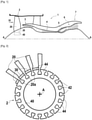
- the figure 1 shows a schematic view in longitudinal section of a turbomachine 1 centered on the axis A around which the turbomachine extends. It comprises, from upstream to downstream: a fan 2, a low pressure compressor 3, a high pressure compressor 4, a combustion chamber 5, a high pressure turbine 6, and a low pressure turbine 7.
- the figure 2 shows a schematic view of the fan 2 of the figure 1 according to direction II.
- the fan 2 comprises a fan disc 40 in which a plurality of grooves 42 are made at its outer periphery. These grooves 42 are rectilinear and extend axially from upstream to downstream all along the disc 40. They are also regularly distributed all around the axis A of the disc 40. In this way, each groove 42 defines with its neighbor a tooth 44 which also extends axially from upstream to downstream all along the disc 40. Equivalently, a groove 42 is delimited by two circumferentially adjacent teeth 44.
- the fan 2 further comprises a plurality of blades 20 of curvilinear profile (only four blades 20 have been shown on the figure 2 ).
- Each blade 20 has a root 20a which is mounted in a respective groove 42 of the fan disk 40.
- the root 20a of a blade 20 can have a fir tree or dovetail shape adapted to the geometry of the grooves 42, each foot 20a having a shape at least partly complementary to the shape of the groove 42 in which it is mounted.
- the fan 2 comprises a plurality of added platforms 30, each platform 30 being mounted in the interval which extends circumferentially between two adjacent fan blades 20, in the vicinity of the feet 20a thereof, in order to delimit, from the interior side, an annular air inlet duct in the fan 2, the duct being delimited on the exterior side by a fan casing (not shown).
- each edge, or circumferential end 32a, 32b, of each platform 30, respectively facing the side of the lower surface 22a and the side of the upper surface 22b of a blade 20, is respectively equipped with a seal 100 and a seal 100' according to the prior art, extending along said circumferential ends 32a, 32b in the axial direction.
- the seal 100 is configured to cooperate with the blade 20 on the side of the lower surface 22a while the seal 100' is configured to cooperate with the blade 20 on the side of the lower surface 22b.
- a displacement of a first blade 20 (the one on the left on the picture 3 ) in the circumferential direction Y tends to exert a pressure on seal 100.
- a movement of a second blade 20 (the one on the right on the picture 3 ) in the same circumferential direction Y tends to move this blade 20 away from the gasket 100' (arrow on the picture 3 ).
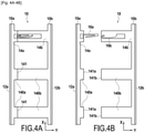
- the figures 4A and 4B schematically represent a bottom view of a seal 10 according to the invention when the first and second parts of the seal are joined ( figure 4A ) and disjoint ( figure 4B ).
- the X axis represents the axial direction
- the Y axis represents the circumferential direction.
- the seal 10 is mounted on a platform 30, itself mounted on a fan disk
- the axis X is substantially parallel to the central axis A of the turbojet engine.
- the circumferential ends of the seal 10 have a rectilinear shape in the axial direction X. This illustration is schematic, the seal 10 not being limited to this shape.
- the circumferential ends of the seal 10 can have a curved shape, so as to match the shape of the profile of the blade with which they are in contact when the seal 10 is mounted on a fan platform.
- the face of the seal 10 illustrated on the figures 4A and 4B in this bottom view, is the face facing the axis of the fan when the seal 10 is mounted on a fan platform, in other words, the radially inner face of the seal 10.
- the seal 10 comprises a first part 10a and a second part 10b, distinct from the first part 10a.
- the first part 10a comprises a first contact portion 12a, and a first structural portion 14a, fixed to each other, for example by gluing.
- the second part 10b comprises a second contact portion 12b, and a second structural portion 14b, fixed to each other, for example by gluing.
- the contact portions 12a, 12b each comprise an elastomeric material, and are intended to be in contact, respectively, with the circumferential end 32a of the platform 30 and a blade adjacent to said circumferential end 32a, and the circumferential end 32b of the platform 30 and a vane adjacent to said circumferential end 32b.
- the structural portions 14a, 14b each comprise a metallic material, for example an aluminum alloy, and may also comprise a carbon composite. Alternatively, the structural portions may comprise an elastomer having a part embedded in aluminum alloy, or be entirely metallic, in aluminum or titanium alloy.
- the first structural portion 14a comprises three tongues 140a
- the second structural portion 14b also comprises three tongues 140b.
- the circumferential ends 141a of the tongues 140a of the first structural portion 14a are configured to come into contact with the circumferential ends 141b of the tongues 140b of the second structural portion 14b, when the first and the second part 10a, 10b of the joint are assembled.
- the tongues 140a of the first structural portion 14a are shorter, in the circumferential direction, than the tongues 140b of the second structural portion 14b.
- the gasket 10 is not limited to this structure.
- the tongues 140a, 140b can for example have an equal length.
- the dimension of the tongues in the axial direction X is given by way of illustration on the Figures 4A, 4B , and may vary depending on the structure of the platform 30 on which the seal 10 is mounted.
- the number of these tongues can also vary, and can be less or more than three for each structural portion 14a, 14b, each tongue 140a of the first structural portion 14a having to be opposite each other, in the circumferential direction Y, with a tongue 140b of the second structural portion 14b.
- the seal 10 comprises a first attachment part 16a fixed to a tongue 140a of the first structural portion 14a, and a second attachment part 16b, fixed to a tongue 140b of the second structural portion 14b.
- These attachment parts 16a, 16b are fixed to a radially inner face of the seal 10, when the latter is mounted on a platform 30 of the fan.
- a single pair of fastener portions 16a, 16b is shown.
- a first attachment part 16a can be provided on two, or on each tongue 140a of the first structural portion 14a.
- a second attachment part 16b can be provided on two, or on each tongue 140b of the second structural portion 14b.
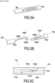
- the figures 5A and 5B show a perspective view of a first and a second attachment part 16a, 16b of the seal 10 according to the invention, when these are in the locked position and in the unlocked position respectively.
- the first attachment part 16a comprises a first attachment portion 161a, fixed to the tongue 140a, for example by welding, and a first pin part 162a, comprising a first branch 162a1 extending in the circumferential direction from the fixing 161a, and a second leg 162a2 extending from the circumferential end of the first leg 162a1 towards the fixing portion 161a.
- the second attachment part 16b comprises a second attachment portion 161b, fixed to the tongue 140b, for example by welding, and a second pin part 162b, comprising a first branch 162b1 extending in the circumferential direction from the attachment 161b, and a hook 162b2, extending from the first branch 162b1 such that the end of the hook 162b2 is directed towards the attachment portion 161b.
- the second branch 162a2 of the first pin part 162a slides along the hook 162b2 of the second pin part 162b, by elastically deforming so as to approach the first branch 162a1.
- the first and the second part 10a, 10b of the gasket 10 are brought closer together, so that the circumferential ends 141a and 141b of the tabs 140a, 140b come into abutment with each other along a contact surface 141, the end of the second branch 162a2 of the first hairpin part 162a passes over the hook end 162b2 moving away again from the first branch 162a1, when the first part d hairpin 162a returns to its original shape.
- the first and the second attachment part 16a, 16b are thus in the locked position, and the first and the second part 10a, 10b are then joined to each other. It is also possible to separate the two parts 10a, 10b from each other, by exerting a force on the first part 10a in the axial direction X, so as to release the second branch 162a2 from the hook 162b2.
- the Fig. 5C shows a perspective view of a first and a second attachment part 17a, 17b of the seal 10 of the invention according to an alternative example, when these are in the locked position.
- the first attachment part 17a comprises a first attachment portion 171a, fixed to the tongue 140a, for example by welding, and a first toothed part 172a extending in the circumferential direction from the attachment portion 171a, the first toothed part 172a comprising a first step 172a1 extending perpendicularly to the circumferential direction.
- the second fastening part 17b comprises a second fastening portion 171b, fixed to the tab 140b, for example by welding, and a second toothed part 172b extending in the circumferential direction from the fastening portion 171b, the second toothed part 172b comprising a second step 172b1 extending perpendicularly to the circumferential direction.
- the Figure 6A shows a perspective view from above of a platform 30 according to the invention, on which is mounted a seal 10, and the figure 6B represents a side section of the platform of the Figure 6A according to a VIB-VIB cutting plane.
- the platform 30 comprises a box 32 making it possible to maintain the vein wall 34 in position, and also to limit its deformations under the effect of centrifugal forces.
- the box 32 also includes a bottom surface 36 able to rest on a tooth 44 of the disk 40 of the fan.
- the box 32 has lateral passages 38 in its radially outer part, radially under the vein wall 34.
- Each structural portion 14a, 14b has as many tongues 140a, 140b as there are passages 38.
- the first part 10a is inserted radially under the vein wall 34 from a circumferential end 32a of the platform 30, passing the tabs 140a through the passages 38.
- the second part 10b is inserted radially under the vein wall 34 from the other circumferential end 32b of the platform 30, passing the tongues 140b through the passages 38, until the lateral ends 141a, 141b come into contact with each other. the others according to the contact surface 141, and that the first and second attachment parts 16a, 16b are in the locked position.
- the figure 7 represents a view in section along a plane parallel to the circumferential direction of the platform 30, at the level of a passage 38.
- the contact portions 12a, 12b have a rectangular section.
- this shape is not limiting, other shapes allowing the contact portions 12a, 12b to slide partly radially under the vein wall 34 are possible.
- the contact portions may for example have a flared shape towards the zone of contact with the blade, or a substantially T-shaped shape, as illustrated in the picture 3 .
Landscapes
- Engineering & Computer Science (AREA)
- Mechanical Engineering (AREA)
- General Engineering & Computer Science (AREA)
- Structures Of Non-Positive Displacement Pumps (AREA)
- Turbine Rotor Nozzle Sealing (AREA)
- Gasket Seals (AREA)
- Sealing Devices (AREA)
Claims (8)
- Zwischenschaufelplattform (30), die eine Dichtung (10) umfasst, die dazu bestimmt ist, sich in Umfangsrichtung um eine Achse zu erstrecken und zwischen zwei axialen Enden der Zwischenschaufelplattform (30) montiert zu sein, wobei die Dichtung (10) mindestens einen ersten Teil (10a), der dazu ausgestaltet ist, mit einer ersten Schaufel (20) in Kontakt zu sein, die in Umfangsrichtung einem ersten Umfangsende (32a) der Plattform (30) benachbart ist, und mindestens einen zweiten Teil (10b) umfasst, der dazu ausgestaltet ist, mit einer zweiten Schaufel (20) in Kontakt zu sein, die in Umfangsrichtung einem zweiten Umfangsende (32b) der Plattform (30) benachbart ist, wobei der erste Teil (10a) und der zweite Teil (10b) der Dichtung (10) sich voneinander unterscheiden und dazu ausgestaltet sind, derart aneinander befestigt zu werden, dass eine Verlagerung von einem von dem ersten oder dem zweiten Teil (10a, 10b) der Dichtung (10) in einer Umfangsrichtung eine Verlagerung des anderen von dem ersten oder dem zweiten Teil (10a, 10b) der Dichtung (10) in der gleichen Richtung verursacht, wenn der erste Teil (10a) und der zweite Teil (10b) der Dichtung (10) aneinander befestigt sind,
wobei die Plattform (30) dadurch gekennzeichnet ist, dass ein erster und/oder ein zweiter Strukturabschnitt (14a, 14b) der Dichtung (10) mindestens eine Lasche (140a, 140b) umfasst, und dadurch, dass sie einen Kasten (32) umfasst, die durch eine Bahnwand (34) abgegrenzt ist, um eine Luftströmungsbahn zu definieren, wobei der Kasten (32) mindestens einen seitlichen Durchgang (38) umfasst, wobei der mindestens eine seitliche Durchgang (38) eine Umfangsöffnung ist, die radial unter der Bahnwand (34) angeordnet ist und dazu ausgestaltet ist, die mindestens eine Lasche (140a, 140b) aufzunehmen und die Verlagerung der Dichtung (10), die sich auf beiden Seiten der Plattform (30) in einer Umfangsrichtung erstreckt, radial unter der Bahnwand (34) zu erlauben. - Plattform (30) nach Anspruch 1, wobei der erste Teil (10a) der Dichtung (10b) einen ersten Kontaktabschnitt (12a) aus einem Elastomermaterial umfasst, wobei der erste Kontaktabschnitt (12a) dazu ausgestaltet ist, mit dem ersten Umfangsende (32a) der Plattform (30) und der ersten Schaufel (20), die dem ersten Umfangsende (32a) der Plattform (30) in Umfangsrichtung benachbart ist, in Kontakt zu sein, und der zweite Teil (10b) der Dichtung (10) einen zweiten Kontaktabschnitt (12b) aus einem Elastomermaterial umfasst, wobei der zweite Kontaktabschnitt (12b) dazu ausgestaltet ist, mit dem zweiten Umfangsende (32b) der Plattform (30) und der zweiten Schaufel (20), die dem zweiten Umfangsende (32b) der Plattform (30) in Umfangsrichtung benachbart ist, in Kontakt zu sein.
- Plattform (30) nach Anspruch 1 oder 2, wobei der erste Teil (10a) der Dichtung (10) den ersten Strukturabschnitt (14a) umfasst und der zweite Teil (10b) der Dichtung (10) den zweiten Strukturabschnitt (14b) umfasst, wobei der erste Strukturabschnitt (14a) und der zweite Strukturabschnitt (14b) dazu ausgestaltet sind, miteinander zusammengefügt zu sein.
- Plattform (30) nach Anspruch 3, wobei jeder von dem ersten und dem zweiten Strukturabschnitt (14a, 14b) ein Metallmaterial umfasst.
- Plattform (30) nach Anspruch 3 oder 4, wobei die mindestens eine Lasche (140a, 140b) sich in Umfangsrichtung erstreckt, wobei ein Umfangsende (141a, 141b) der Lasche (140a, 140b) dazu ausgestaltet ist, mit dem anderen von dem ersten und dem zweiten Strukturabschnitt (14a, 14b) in Kontakt zu gelangen.
- Plattform (30) nach Anspruch 5, wobei der erste Teil der Dichtung (10a) mindestens einen ersten Anbringungsteil (16a) umfasst, der an einer Lasche (140a) des ersten Strukturabschnitts (14a) befestigt ist, und der zweite Teil (10b) der Dichtung (10) mindestens einen zweiten Anbringungsteil (16b) umfasst, der an einer Lasche (140b) des zweiten Strukturabschnitts (14b) befestigt ist, wobei der erste und der zweite Anbringungsteil (16a, 16b) dazu ausgestaltet sind, derart miteinander zusammenzuwirken, dass der erste Teil (10a) der Dichtung (10) an dem zweiten Teil (10b) der Dichtung (10) angefügt wird.
- Rotor, der eine Scheibe (40) umfasst, an deren Umfang eine Vielzahl von Schaufeln (20) und eine Vielzahl von Zwischenschaufelplattformen (30) nach einem der Ansprüche 1 bis 6 montiert sind, wobei jede Plattform (30) zwischen jedem Paar von in Umfangsrichtung benachbarten Schaufeln (20) angeordnet ist.
- Turbomaschine (1), die einen Rotor nach Anspruch 7 umfasst.
Applications Claiming Priority (1)
| Application Number | Priority Date | Filing Date | Title |
|---|---|---|---|
| FR1900080A FR3091563B1 (fr) | 2019-01-04 | 2019-01-04 | Joint d’étanchéité amélioré de plateforme inter-aubes |
Publications (2)
| Publication Number | Publication Date |
|---|---|
| EP3677752A1 EP3677752A1 (de) | 2020-07-08 |
| EP3677752B1 true EP3677752B1 (de) | 2022-02-09 |
Family
ID=66690619
Family Applications (1)
| Application Number | Title | Priority Date | Filing Date |
|---|---|---|---|
| EP19220063.2A Active EP3677752B1 (de) | 2019-01-04 | 2019-12-30 | Verbesserte dichtungsanordnung für eine zwischenschaufelplattform |
Country Status (4)
| Country | Link |
|---|---|
| US (1) | US11078918B2 (de) |
| EP (1) | EP3677752B1 (de) |
| CN (1) | CN111412178B (de) |
| FR (1) | FR3091563B1 (de) |
Families Citing this family (5)
| Publication number | Priority date | Publication date | Assignee | Title |
|---|---|---|---|---|
| IT201900002209A1 (it) * | 2019-02-15 | 2020-08-15 | Ilpea Ind Spa | Guarnizione per lavastoviglie, lavastoviglie comprendente tale guarnizione e metodo di assemblaggio associato |
| US11268396B2 (en) * | 2020-01-17 | 2022-03-08 | Raytheon Technologies Corporation | Turbine fan fairing platform with protective surface |
| US12180845B1 (en) * | 2023-06-07 | 2024-12-31 | Spirit Aerosystems, Inc. | Aircraft duct assembly and sealing structure |
| FR3154760A1 (fr) | 2023-10-31 | 2025-05-02 | Safran Aircraft Engines | Ensemble rotatif de turbomachine d’aéronef comportant une plateforme de soufflante avec butée |
| FR3159627A1 (fr) * | 2024-02-27 | 2025-08-29 | Safran Aircraft Engines | Plateforme inter-aubes pour une helice de turbomachine d’aeronef |
Family Cites Families (22)
| Publication number | Priority date | Publication date | Assignee | Title |
|---|---|---|---|---|
| GB1232506A (de) * | 1969-10-28 | 1971-05-19 | ||
| GB1276106A (en) * | 1969-12-19 | 1972-06-01 | Rolls Royce | FLUID FLOW MACHINE, e.g. GAS TURBINE ENGINE COMPRESSOR |
| FR2669686B1 (fr) * | 1990-11-28 | 1994-09-02 | Snecma | Rotor de soufflante avec aubes sans plates-formes et sabots reconstituant le profil de veine. |
| US6217283B1 (en) * | 1999-04-20 | 2001-04-17 | General Electric Company | Composite fan platform |
| FR2858351B1 (fr) * | 2003-07-31 | 2006-01-13 | Snecma Moteurs | Plate-forme inter-aubes a flechissement lateral, pour un support d'aubes de turboreacteur |
| US7360990B2 (en) * | 2004-10-13 | 2008-04-22 | General Electric Company | Methods and apparatus for assembling gas turbine engines |
| GB0611031D0 (en) * | 2006-06-06 | 2006-07-12 | Rolls Royce Plc | An aerofoil stage and a seal for use therein |
| GB2438858B (en) * | 2006-06-07 | 2008-08-06 | Rolls Royce Plc | A sealing arrangement in a gas turbine engine |
| GB0614640D0 (en) * | 2006-07-22 | 2006-08-30 | Rolls Royce Plc | An annulus filler seal |
| GB0806171D0 (en) * | 2008-04-07 | 2008-05-14 | Rolls Royce Plc | Aeroengine fan assembly |
| FR2939836B1 (fr) * | 2008-12-12 | 2015-05-15 | Snecma | Joint d'etancheite de plateforme dans un rotor de turbomachine |
| GB0910752D0 (en) * | 2009-06-23 | 2009-08-05 | Rolls Royce Plc | An annulus filler for a gas turbine engine |
| FR2965843B1 (fr) * | 2010-10-06 | 2012-11-09 | Snecma | Rotor pour turbomachine |
| GB2489222A (en) * | 2011-03-21 | 2012-09-26 | Rolls Royce Plc | Bladed rotor with annulus filler |
| GB201119655D0 (en) * | 2011-11-15 | 2011-12-28 | Rolls Royce Plc | Annulus filler |
| FR2987086B1 (fr) * | 2012-02-22 | 2014-03-21 | Snecma | Joint lineaire de plateforme inter-aubes |
| EP2883688B1 (de) * | 2013-12-13 | 2021-09-22 | Safran Aero Boosters SA | Ringförmiges Verbundwerkstoffgehäuse für einen Turbomaschinenkompressor und Verfahren zu seiner Herstellung |
| EP3080418B1 (de) * | 2013-12-13 | 2020-06-24 | United Technologies Corporation | Kantenabdichtung zur plattform eines bläsers |
| BE1023134B1 (fr) * | 2015-05-27 | 2016-11-29 | Techspace Aero S.A. | Aube et virole a fourreau de compresseur de turbomachine axiale |
| BE1023233B1 (fr) * | 2015-07-01 | 2017-01-05 | Safran Aero Boosters S.A. | Tambour perfore de compresseur de turbomachine axiale |
| FR3052822B1 (fr) * | 2016-06-16 | 2020-03-27 | Safran Aircraft Engines | Aube de turbomachine equipee d'un joint en elastomere |
| DE102016211337A1 (de) * | 2016-06-24 | 2017-12-28 | MTU Aero Engines AG | Verdickter radial äußerer Ringbereich eines Dichtfins |
-
2019
- 2019-01-04 FR FR1900080A patent/FR3091563B1/fr active Active
- 2019-12-30 EP EP19220063.2A patent/EP3677752B1/de active Active
-
2020
- 2020-01-03 CN CN202010004907.0A patent/CN111412178B/zh active Active
- 2020-01-03 US US16/733,620 patent/US11078918B2/en active Active
Also Published As
| Publication number | Publication date |
|---|---|
| CN111412178A (zh) | 2020-07-14 |
| FR3091563B1 (fr) | 2023-01-20 |
| US20200217217A1 (en) | 2020-07-09 |
| CN111412178B (zh) | 2023-12-05 |
| US11078918B2 (en) | 2021-08-03 |
| FR3091563A1 (fr) | 2020-07-10 |
| EP3677752A1 (de) | 2020-07-08 |
Similar Documents
| Publication | Publication Date | Title |
|---|---|---|
| EP3677752B1 (de) | Verbesserte dichtungsanordnung für eine zwischenschaufelplattform | |
| CA2715454C (fr) | Distributeur sectorise pour une turbomachine | |
| EP2060750B1 (de) | Turbinen- oder Kompressorstufe, insbesondere eines Turbotriebwerks | |
| EP2366061B1 (de) | Turbinenrad mit einem axialrückhaltesystem für schaufeln | |
| FR2989724A1 (fr) | Etage de turbine pour une turbomachine | |
| FR2875262A1 (fr) | Procedes et dispositifs pour assembler des ensembles de rotors de moteurs a turbines a gaz | |
| CA2647057C (fr) | Distributeur sectorise pour une turbomachine | |
| EP1517005A1 (de) | Gasturbine mit einem Abdichtdelement mit Lamellenstruktur | |
| EP3201438B1 (de) | Laufschaufel einer turbomaschine mit einem flansch, der an einer sperrkerbe in der rotorscheibe anliegt | |
| EP1517006A1 (de) | Gasturbine mit Bürstendichtung | |
| EP3433469A1 (de) | Gebläseanordnung, platte und plattform | |
| EP1630350B1 (de) | Laufschaufel eines Verdichters oder einer Gasturbine | |
| CA2644312C (fr) | Etage de turbine ou de compresseur de turbomachine | |
| FR2965843A1 (fr) | Rotor pour turbomachine | |
| WO2022049338A1 (fr) | Turbine pour turbomachine comprenant des clinquants de protection thermique | |
| FR2874403A1 (fr) | Aube de compresseur ou de turbune a gaz | |
| EP4544155B1 (de) | Beschaufelte anordnung für turbomaschine, turbine für turbomaschine und turbomaschine | |
| EP3797224B1 (de) | Verbesserte fanscheibe für eine turbomaschine | |
| EP3683450A1 (de) | Rotoranordnung einer strömungsmaschine | |
| FR3085708A1 (fr) | Dispositif d'etancheite ameliore pour ensemble rotatif de turbomachine | |
| FR2960590A1 (fr) | Distributeur de turbine pour une turbomachine | |
| WO2024194575A1 (fr) | Roue aubagée pour turbomachine d'aéronef et turbomachine d'aéronef | |
| FR3154760A1 (fr) | Ensemble rotatif de turbomachine d’aéronef comportant une plateforme de soufflante avec butée | |
| WO2025219679A1 (fr) | Roue de turbine de turbomachine d'aéronef d'axe longitudinal, turbine pour turbomachine d'aéronef d'axe longitudinal, turbomachine d'aéronef d'axe longitudinal, et aéronef | |
| FR3108674A1 (fr) | Assemblage a etancheite renforcee pour turbomachine d’aeronef, comprenant une roue aubagee de stator ainsi qu’un carter exterieur agence autour de la roue aubagee |
Legal Events
| Date | Code | Title | Description |
|---|---|---|---|
| PUAI | Public reference made under article 153(3) epc to a published international application that has entered the european phase |
Free format text: ORIGINAL CODE: 0009012 |
|
| STAA | Information on the status of an ep patent application or granted ep patent |
Free format text: STATUS: REQUEST FOR EXAMINATION WAS MADE |
|
| 17P | Request for examination filed |
Effective date: 20191230 |
|
| AK | Designated contracting states |
Kind code of ref document: A1 Designated state(s): AL AT BE BG CH CY CZ DE DK EE ES FI FR GB GR HR HU IE IS IT LI LT LU LV MC MK MT NL NO PL PT RO RS SE SI SK SM TR |
|
| GRAP | Despatch of communication of intention to grant a patent |
Free format text: ORIGINAL CODE: EPIDOSNIGR1 |
|
| STAA | Information on the status of an ep patent application or granted ep patent |
Free format text: STATUS: GRANT OF PATENT IS INTENDED |
|
| INTG | Intention to grant announced |
Effective date: 20211117 |
|
| GRAS | Grant fee paid |
Free format text: ORIGINAL CODE: EPIDOSNIGR3 |
|
| GRAA | (expected) grant |
Free format text: ORIGINAL CODE: 0009210 |
|
| STAA | Information on the status of an ep patent application or granted ep patent |
Free format text: STATUS: THE PATENT HAS BEEN GRANTED |
|
| AK | Designated contracting states |
Kind code of ref document: B1 Designated state(s): AL AT BE BG CH CY CZ DE DK EE ES FI FR GB GR HR HU IE IS IT LI LT LU LV MC MK MT NL NO PL PT RO RS SE SI SK SM TR |
|
| REG | Reference to a national code |
Ref country code: GB Ref legal event code: FG4D Free format text: NOT ENGLISH |
|
| REG | Reference to a national code |
Ref country code: CH Ref legal event code: EP Ref country code: AT Ref legal event code: REF Ref document number: 1467634 Country of ref document: AT Kind code of ref document: T Effective date: 20220215 |
|
| REG | Reference to a national code |
Ref country code: DE Ref legal event code: R096 Ref document number: 602019011483 Country of ref document: DE |
|
| REG | Reference to a national code |
Ref country code: IE Ref legal event code: FG4D Free format text: LANGUAGE OF EP DOCUMENT: FRENCH |
|
| REG | Reference to a national code |
Ref country code: SE Ref legal event code: TRGR |
|
| REG | Reference to a national code |
Ref country code: LT Ref legal event code: MG9D |
|
| REG | Reference to a national code |
Ref country code: NL Ref legal event code: MP Effective date: 20220209 |
|
| REG | Reference to a national code |
Ref country code: AT Ref legal event code: MK05 Ref document number: 1467634 Country of ref document: AT Kind code of ref document: T Effective date: 20220209 |
|
| PG25 | Lapsed in a contracting state [announced via postgrant information from national office to epo] |
Ref country code: RS Free format text: LAPSE BECAUSE OF FAILURE TO SUBMIT A TRANSLATION OF THE DESCRIPTION OR TO PAY THE FEE WITHIN THE PRESCRIBED TIME-LIMIT Effective date: 20220209 Ref country code: PT Free format text: LAPSE BECAUSE OF FAILURE TO SUBMIT A TRANSLATION OF THE DESCRIPTION OR TO PAY THE FEE WITHIN THE PRESCRIBED TIME-LIMIT Effective date: 20220609 Ref country code: NO Free format text: LAPSE BECAUSE OF FAILURE TO SUBMIT A TRANSLATION OF THE DESCRIPTION OR TO PAY THE FEE WITHIN THE PRESCRIBED TIME-LIMIT Effective date: 20220509 Ref country code: NL Free format text: LAPSE BECAUSE OF FAILURE TO SUBMIT A TRANSLATION OF THE DESCRIPTION OR TO PAY THE FEE WITHIN THE PRESCRIBED TIME-LIMIT Effective date: 20220209 Ref country code: LT Free format text: LAPSE BECAUSE OF FAILURE TO SUBMIT A TRANSLATION OF THE DESCRIPTION OR TO PAY THE FEE WITHIN THE PRESCRIBED TIME-LIMIT Effective date: 20220209 Ref country code: HR Free format text: LAPSE BECAUSE OF FAILURE TO SUBMIT A TRANSLATION OF THE DESCRIPTION OR TO PAY THE FEE WITHIN THE PRESCRIBED TIME-LIMIT Effective date: 20220209 Ref country code: ES Free format text: LAPSE BECAUSE OF FAILURE TO SUBMIT A TRANSLATION OF THE DESCRIPTION OR TO PAY THE FEE WITHIN THE PRESCRIBED TIME-LIMIT Effective date: 20220209 Ref country code: BG Free format text: LAPSE BECAUSE OF FAILURE TO SUBMIT A TRANSLATION OF THE DESCRIPTION OR TO PAY THE FEE WITHIN THE PRESCRIBED TIME-LIMIT Effective date: 20220509 |
|
| PG25 | Lapsed in a contracting state [announced via postgrant information from national office to epo] |
Ref country code: PL Free format text: LAPSE BECAUSE OF FAILURE TO SUBMIT A TRANSLATION OF THE DESCRIPTION OR TO PAY THE FEE WITHIN THE PRESCRIBED TIME-LIMIT Effective date: 20220209 Ref country code: LV Free format text: LAPSE BECAUSE OF FAILURE TO SUBMIT A TRANSLATION OF THE DESCRIPTION OR TO PAY THE FEE WITHIN THE PRESCRIBED TIME-LIMIT Effective date: 20220209 Ref country code: GR Free format text: LAPSE BECAUSE OF FAILURE TO SUBMIT A TRANSLATION OF THE DESCRIPTION OR TO PAY THE FEE WITHIN THE PRESCRIBED TIME-LIMIT Effective date: 20220510 Ref country code: FI Free format text: LAPSE BECAUSE OF FAILURE TO SUBMIT A TRANSLATION OF THE DESCRIPTION OR TO PAY THE FEE WITHIN THE PRESCRIBED TIME-LIMIT Effective date: 20220209 Ref country code: AT Free format text: LAPSE BECAUSE OF FAILURE TO SUBMIT A TRANSLATION OF THE DESCRIPTION OR TO PAY THE FEE WITHIN THE PRESCRIBED TIME-LIMIT Effective date: 20220209 |
|
| PG25 | Lapsed in a contracting state [announced via postgrant information from national office to epo] |
Ref country code: IS Free format text: LAPSE BECAUSE OF FAILURE TO SUBMIT A TRANSLATION OF THE DESCRIPTION OR TO PAY THE FEE WITHIN THE PRESCRIBED TIME-LIMIT Effective date: 20220609 |
|
| PG25 | Lapsed in a contracting state [announced via postgrant information from national office to epo] |
Ref country code: SM Free format text: LAPSE BECAUSE OF FAILURE TO SUBMIT A TRANSLATION OF THE DESCRIPTION OR TO PAY THE FEE WITHIN THE PRESCRIBED TIME-LIMIT Effective date: 20220209 Ref country code: SK Free format text: LAPSE BECAUSE OF FAILURE TO SUBMIT A TRANSLATION OF THE DESCRIPTION OR TO PAY THE FEE WITHIN THE PRESCRIBED TIME-LIMIT Effective date: 20220209 Ref country code: RO Free format text: LAPSE BECAUSE OF FAILURE TO SUBMIT A TRANSLATION OF THE DESCRIPTION OR TO PAY THE FEE WITHIN THE PRESCRIBED TIME-LIMIT Effective date: 20220209 Ref country code: EE Free format text: LAPSE BECAUSE OF FAILURE TO SUBMIT A TRANSLATION OF THE DESCRIPTION OR TO PAY THE FEE WITHIN THE PRESCRIBED TIME-LIMIT Effective date: 20220209 Ref country code: DK Free format text: LAPSE BECAUSE OF FAILURE TO SUBMIT A TRANSLATION OF THE DESCRIPTION OR TO PAY THE FEE WITHIN THE PRESCRIBED TIME-LIMIT Effective date: 20220209 Ref country code: CZ Free format text: LAPSE BECAUSE OF FAILURE TO SUBMIT A TRANSLATION OF THE DESCRIPTION OR TO PAY THE FEE WITHIN THE PRESCRIBED TIME-LIMIT Effective date: 20220209 |
|
| REG | Reference to a national code |
Ref country code: DE Ref legal event code: R097 Ref document number: 602019011483 Country of ref document: DE |
|
| PG25 | Lapsed in a contracting state [announced via postgrant information from national office to epo] |
Ref country code: AL Free format text: LAPSE BECAUSE OF FAILURE TO SUBMIT A TRANSLATION OF THE DESCRIPTION OR TO PAY THE FEE WITHIN THE PRESCRIBED TIME-LIMIT Effective date: 20220209 |
|
| PLBE | No opposition filed within time limit |
Free format text: ORIGINAL CODE: 0009261 |
|
| STAA | Information on the status of an ep patent application or granted ep patent |
Free format text: STATUS: NO OPPOSITION FILED WITHIN TIME LIMIT |
|
| 26N | No opposition filed |
Effective date: 20221110 |
|
| PG25 | Lapsed in a contracting state [announced via postgrant information from national office to epo] |
Ref country code: SI Free format text: LAPSE BECAUSE OF FAILURE TO SUBMIT A TRANSLATION OF THE DESCRIPTION OR TO PAY THE FEE WITHIN THE PRESCRIBED TIME-LIMIT Effective date: 20220209 |
|
| REG | Reference to a national code |
Ref country code: CH Ref legal event code: PL |
|
| REG | Reference to a national code |
Ref country code: BE Ref legal event code: MM Effective date: 20221231 |
|
| PG25 | Lapsed in a contracting state [announced via postgrant information from national office to epo] |
Ref country code: LU Free format text: LAPSE BECAUSE OF NON-PAYMENT OF DUE FEES Effective date: 20221230 |
|
| PG25 | Lapsed in a contracting state [announced via postgrant information from national office to epo] |
Ref country code: LI Free format text: LAPSE BECAUSE OF NON-PAYMENT OF DUE FEES Effective date: 20221231 Ref country code: IE Free format text: LAPSE BECAUSE OF NON-PAYMENT OF DUE FEES Effective date: 20221230 Ref country code: CH Free format text: LAPSE BECAUSE OF NON-PAYMENT OF DUE FEES Effective date: 20221231 |
|
| PG25 | Lapsed in a contracting state [announced via postgrant information from national office to epo] |
Ref country code: BE Free format text: LAPSE BECAUSE OF NON-PAYMENT OF DUE FEES Effective date: 20221231 |
|
| PG25 | Lapsed in a contracting state [announced via postgrant information from national office to epo] |
Ref country code: HU Free format text: LAPSE BECAUSE OF FAILURE TO SUBMIT A TRANSLATION OF THE DESCRIPTION OR TO PAY THE FEE WITHIN THE PRESCRIBED TIME-LIMIT; INVALID AB INITIO Effective date: 20191230 |
|
| PG25 | Lapsed in a contracting state [announced via postgrant information from national office to epo] |
Ref country code: CY Free format text: LAPSE BECAUSE OF FAILURE TO SUBMIT A TRANSLATION OF THE DESCRIPTION OR TO PAY THE FEE WITHIN THE PRESCRIBED TIME-LIMIT Effective date: 20220209 |
|
| PG25 | Lapsed in a contracting state [announced via postgrant information from national office to epo] |
Ref country code: MK Free format text: LAPSE BECAUSE OF FAILURE TO SUBMIT A TRANSLATION OF THE DESCRIPTION OR TO PAY THE FEE WITHIN THE PRESCRIBED TIME-LIMIT Effective date: 20220209 |
|
| PG25 | Lapsed in a contracting state [announced via postgrant information from national office to epo] |
Ref country code: MC Free format text: LAPSE BECAUSE OF FAILURE TO SUBMIT A TRANSLATION OF THE DESCRIPTION OR TO PAY THE FEE WITHIN THE PRESCRIBED TIME-LIMIT Effective date: 20220209 |
|
| PG25 | Lapsed in a contracting state [announced via postgrant information from national office to epo] |
Ref country code: MC Free format text: LAPSE BECAUSE OF FAILURE TO SUBMIT A TRANSLATION OF THE DESCRIPTION OR TO PAY THE FEE WITHIN THE PRESCRIBED TIME-LIMIT Effective date: 20220209 |
|
| PG25 | Lapsed in a contracting state [announced via postgrant information from national office to epo] |
Ref country code: MT Free format text: LAPSE BECAUSE OF FAILURE TO SUBMIT A TRANSLATION OF THE DESCRIPTION OR TO PAY THE FEE WITHIN THE PRESCRIBED TIME-LIMIT Effective date: 20220209 |
|
| PG25 | Lapsed in a contracting state [announced via postgrant information from national office to epo] |
Ref country code: TR Free format text: LAPSE BECAUSE OF FAILURE TO SUBMIT A TRANSLATION OF THE DESCRIPTION OR TO PAY THE FEE WITHIN THE PRESCRIBED TIME-LIMIT Effective date: 20220209 |
|
| PGFP | Annual fee paid to national office [announced via postgrant information from national office to epo] |
Ref country code: GB Payment date: 20251229 Year of fee payment: 7 |
|
| PGFP | Annual fee paid to national office [announced via postgrant information from national office to epo] |
Ref country code: FR Payment date: 20251222 Year of fee payment: 7 |
|
| PGFP | Annual fee paid to national office [announced via postgrant information from national office to epo] |
Ref country code: SE Payment date: 20251217 Year of fee payment: 7 |
|
| PGFP | Annual fee paid to national office [announced via postgrant information from national office to epo] |
Ref country code: DE Payment date: 20251222 Year of fee payment: 7 |
|
| PGFP | Annual fee paid to national office [announced via postgrant information from national office to epo] |
Ref country code: IT Payment date: 20251231 Year of fee payment: 7 |