EP0317521A2 - Verfahren und Einrichtung zur Sterilisation des Zerstäubers und/oder der Luftzufuhr von medizinischen Instrumenten, insbesondere von zahnärztlichen Instrumenten - Google Patents
Verfahren und Einrichtung zur Sterilisation des Zerstäubers und/oder der Luftzufuhr von medizinischen Instrumenten, insbesondere von zahnärztlichen Instrumenten Download PDFInfo
- Publication number
- EP0317521A2 EP0317521A2 EP88830461A EP88830461A EP0317521A2 EP 0317521 A2 EP0317521 A2 EP 0317521A2 EP 88830461 A EP88830461 A EP 88830461A EP 88830461 A EP88830461 A EP 88830461A EP 0317521 A2 EP0317521 A2 EP 0317521A2
- Authority
- EP
- European Patent Office
- Prior art keywords
- instruments
- supply lines
- circuit
- sterilizer
- valves
- Prior art date
- Legal status (The legal status is an assumption and is not a legal conclusion. Google has not performed a legal analysis and makes no representation as to the accuracy of the status listed.)
- Granted
Links
Images
Classifications
-
- A—HUMAN NECESSITIES
- A61—MEDICAL OR VETERINARY SCIENCE; HYGIENE
- A61L—METHODS OR APPARATUS FOR STERILISING MATERIALS OR OBJECTS IN GENERAL; DISINFECTION, STERILISATION OR DEODORISATION OF AIR; CHEMICAL ASPECTS OF BANDAGES, DRESSINGS, ABSORBENT PADS OR SURGICAL ARTICLES; MATERIALS FOR BANDAGES, DRESSINGS, ABSORBENT PADS OR SURGICAL ARTICLES
- A61L2/00—Disinfection or sterilisation of materials or objects, in general; Accessories therefor
- A61L2/16—Disinfection or sterilisation of materials or objects, in general; Accessories therefor using chemical substances
- A61L2/18—Liquid substances
-
- A—HUMAN NECESSITIES
- A61—MEDICAL OR VETERINARY SCIENCE; HYGIENE
- A61C—DENTISTRY; APPARATUS OR METHODS FOR ORAL OR DENTAL HYGIENE
- A61C1/00—Dental machines for boring or cutting ; General features of dental machines or apparatus, e.g. hand-piece design
- A61C1/0061—Air and water supply systems; Valves specially adapted therefor
- A61C1/0076—Sterilising operating fluids or fluid supply elements such as supply lines, filters
Definitions
- the invention relates to a process and device for sterilization of the spray and/or air supply lines to power driven medical instruments, in particular dental surgery instruments.
- German patent DE-OS 28 36 532 discloses a process, and apparatus, for sterilizing the handgrips of medical or dental surgery instruments.
- the process is essentially one of subjecting fluid propellants and/or coolants to the germicidal action of an oxidizing medium, for example anode oxidation or microwave radiation.
- an oxidizing medium for example anode oxidation or microwave radiation.
- German patent DE-OS 30 28 550 A different type of device for sterilizing medical instruments, and for dental surgery instruments in particular, is disclosed in another German patent DE-OS 30 28 550.
- This consists in a container, to which liquid sterilizer is supplied, and a metering pump by which the liquid sterilizer is forced into the spray circuit of each instrument, according to the quantity of water required by the instrument during operation.
- the metering pump is interlocked to control media capable of identifying which instrument is activated, and determining the quantity of liquid sterilizer to be pumped into the spray circuit, likewise according to the quantity of water utilized in operation.
- This device is certainly effective, though only in the case of a continuous sterilization of the water supplied to instruments, at low rates of flow, and only for a limited sterilizing action, given that the disinfectant is pumped into the spray circuit while the instruments are in use; more exactly, the liquid sterilizer mingles with the water sent into the instrument, and thus enters into contact with the internal surfaces of the human body (the mouth, in the instance of dental surgery instruments), and accordingly, the liquid sterilizer and/or its level of concentration in the spray must be formulated and/or calculated to ensure that there is no health risk. As most of the liquid sterilizers currently in use are acids, and toxic, they must be diluted considerably in this type of situation, and thus lose a great deal of their germicidal properties.
- a further drawback of the apparatus in question is its complexity.
- the on-off valves of the single instruments must be held open, whereas these valves are of a normally-closed type designed to open, singly, when the relative instrument is in use. More exactly, the valve can be opened only by removing the instrument from its holder, for obvious expediency; however, in the event that not all of the on-off valves are opened up, due to an oversight or for any other reason, the instrument or instruments remaining 'off' will undergo no sterilizing action whatever.
- the object of the invention is to overcome the drawbacks described above.
- the supply line connecting each instrument to the main spray circuit also connects with at least one plenum chamber, able to generate a soft vacuum, the purpose of which is to prevent the instrument dripping water when switched off by deactivating the on-off valve.
- each plenum will generally be located downstream of the on-off valve on the relative branch of the spray circuit; accordingly, the device disclosed can be connected upstream of and used to sterilize the plenum chambers. This is an important feature, inasmuch as bacteria will inevitably tend to collect in the plenum chamber (or chambers) with continued use of the equipment, and frequent sterilization and/or disinfection is required.
- an additional object of the invention is to embody a device that will also sterilize and/or disinfect, in the case in point, a single plenum chamber incorporated into the equipment column, and if not entirely eliminate, then greatly reduce the bacterial content of water drawn from the domestic system into the spray circuit; the main object stated above is therefore flanked by the further general object of ensuring sterilization of the circuit as a whole.
- the device according to the invention comprises an auxiliary sterilizer circuit connected via relative branches with the instrument supply lines of the spray circuit at points downstream of the on-off valves, which remain closed during sterilization, and this further object is achieved by connecting the plenum in series with both the sterilizer circuit and the spray circuit, and incorporating shut-off means in parallel with the spray circuit and interconnecting the sections of the instrument supply lines upstream and downstream of the on-off valves; thus, it is the shut-off means that open to allow passage of the liquid sterilizer.
- One of the advantages afforded by the invention is essentially that of the sure sterilizating action achieved, especially where sterilizer is flushed out by activating the instruments, as in this case, fluid passing through certain of the instruments can atomize internally of the collection vessel; first to be atomized is the sterilizer, which acts on the tips of the instruments, and immediately thereafter, water from the spray circuit, which both flushes out the internal passages and floods the tips of the handgrips, as well as cleansing the entire collection vessel.
- Another advantage of the invention is its efficient operation; when the sterilizer is flushed out by activating the instruments, in fact, this has the effect of sterilizing those parts associated with though not lying directly in the path of the water, such as the turbine of the high speed drill.
- a further advantage of the invention is that of dependable operation, obtained by sterilizing the instruments with the relative on-off valves in their normally-closed position, in such a way that there are no problems with sterilization failing to take effect, or with sterilizer lingering in the circuits.
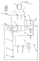
- the device according to the invention is associated with a given number of power driven medical instruments (in practice, the device might be incorporated permanently or used as an accessory, to equally good effect), which in the example illustrated are dental surgery instruments, denoted 3, forming part of a conventional column.
- the single instruments 3 connect with fluid supply lines, denoted 1, controlled by respective on-off valves 2.
- Each supply line 1 (carrying water, for example, as arrowed W in the drawings) constitutes one branch of a main circuit 15 controlled in turn by a main shut-off valve 16.
- These valves 2, 16 will all be connected to a control circuit of conventional type (not illustrated) by means of which to ensure that operation of any one instrument will come about on activation of the relative on-off valve 2 together with the main valve 16.
- the relative valve 2 In short, to operate a given instrument 3, the relative valve 2 must be opened up, generally by lifting the handgrip from its holder in the console table of the equipment column, and the main valve 16 then opened, usually by depressing a foot pedal.
- the device essentially comprises a tank 7 containing a supply of liquid sterilizer 14, an auxiliary circuit 5 connecting with the spray circuit supply lines 1, downstream of the relative on-off valves 2, also, a vessel 4 in which the soiled sterilizer 14 is collected, and in which the instruments 3 are placed and held during the sterilization and collection operations.
- the auxiliary circuit 5 affords as many branches 8 as there are instruments, which connect with the relative supply lines 1 of the spray circuit and incorporate relative check valves 9 disallowing any return of liquids into the circuit 5; a further check valve 6 is fitted to the outlet of the feed pump 10 associated with the supply tank 7.
- the process according to the invention comprises the steps of: -removing the instruments 3 from their holders and placing them in the vessel 4; -switching all the on-off valves 2 to 'off', such that the upstream section of the the respective instrument supply lines 1 remain closed; -supplying sterilizer 14 from the tank 7 to the instruments; -flushing the auxiliary circuit 5 and associated supply lines 1 with a fluid to the end of removing the soiled sterilizer 14; -returning the instruments 3 to their holders.
- the liquid sterilizer 14 may be supplied in either one of two ways, namely, activating a pump 10 that forces the liquid through the auxiliary circuit 5 as mentioned above, or connecting the vessel 4 to means 11 of generating suction (see phantom line in fig 1).
- the vessel 4 will need to be structured in such a way as to afford a fluid-tight seal once the instruments 3 have been placed in it.
- the supply tank 7 will be held at atmospheric pressure, or at all events, will not be pressurized.
- the soiled sterilizer 14 is flushed away by opening up all the on-off valves 2 (which, it will be remembered, have not been in direct contact with the sterilizer) and activating the spray circuit by way of the by-pass valve 17 so as to supply water to the instruments; in this way, one avoids operating the foot pedal to open up the main shut-off valve 16.
- water is sent into the part of the auxiliary circuit 5 downstream of the pump check valve 6 by opening the valve denoted 18.
- the flushing step is accomplished by activating all the instruments 3 in the vessel 4 at once (that is, switching on all the relative supplies of fluid). This constitutes a particularly effective expedient, since there will be an initial explusion, by all the instruments 3 together, of sterilizer 14 still in the parts of the two circuits as mentioned above, i.e. 1, 5, 8, following which, these same parts will be flooded with water.
- the soiled sterilizer 14 is flushed out by leaving the on-off valves 2 closed and blasting the auxiliary circuit 5 downstream of the pump check valve 6 with compressed air.
- the device will comprise a source of compressed air 12 (normally speaking, that of the surgery equipment column itself) and a check valve 13 (illustrated in phantom lines in both of the drawings), located immediately downstream of the pump 10 and its check valve 6, which serves to prevent any return of fluid, air or sterilizer when the source 12 is switched off.
- a source of compressed air 12 normally speaking, that of the surgery equipment column itself
- a check valve 13 illustrated in phantom lines in both of the drawings
- This method of implementing the flushing step is especially practical, as the sterilizer 14 can be removed using a fluid that requires no conditioning and, as a result, is most economical.
- the surgery equipment incorporates one plenum chamber (not illustrated) for each instrument 3 served by a supply line 1, located upstream of the instrument but downstream of the relative branch 8 of the auxiliary circuit 5.
- a plenum chamber for each instrument 3 served by a supply line 1, located upstream of the instrument but downstream of the relative branch 8 of the auxiliary circuit 5.
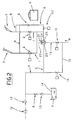
- this will be connected in series with the spray circuit 15 at a point upstream of the various supply lines 1.
- the plenum 21 generally will be piloted by an air line 23 (phantom in fig 2) taken off from the air spray or propellant supply to the instruments 3 in conventional manner (not shown).
- the plenum 21 will consist in a spring biased piston 24 accommodated slidably and fluid-tight internally of a relative cylinder 25; the spring is denoted 26.
- the plenum air line 23 enters the end of the cylinder 25 not occupied by the spring 26, whilst water enters and leaves the spring end, in such a way that the spray circuit 15 incorporates the plenum in series.
- the auxiliary circuit 5 passes through the plenum 21 in parallel with the spray circuit 15: that is, the plenum 21 is connected in series with both circuits 5 and 15.
- shut-off valve 22 located between the plenum 21 and the downstream check valve 9 (one only, controlling all the branches 8), whereas the by-pass 17 is dispensed with.
- the user places the instruments 3 in the vessel 4 and opens the shut-off valve denoted 22; the remaining valves 2, 16 and 18 are left closed.
- sterilizer is transferred by the pump 10 through the auxiliary circuit 5, the plenum 21 and the branches 8 downstream of the on-off valves 2, and into the instruments 3.
- the sterilizer 14 can be either flushed out by opening up the valve denoted 18 (by-passing the pedal-operated valve 16) or blasted out by directing compressed air from the source 12 into the parts of the circuits 5, 8 and 15 occupied; in either event, the soiled sterilizer will be removed completely from these passages.
- the shut-off valve 22 is then closed, and remains closed throughout normal operation to ensure that water is admitted to the instruments 3 only by way of the relative spray circuit supply lines 1.
Landscapes
- Health & Medical Sciences (AREA)
- Public Health (AREA)
- Veterinary Medicine (AREA)
- General Health & Medical Sciences (AREA)
- Epidemiology (AREA)
- Life Sciences & Earth Sciences (AREA)
- Animal Behavior & Ethology (AREA)
- Water Supply & Treatment (AREA)
- General Chemical & Material Sciences (AREA)
- Chemical Kinetics & Catalysis (AREA)
- Engineering & Computer Science (AREA)
- Chemical & Material Sciences (AREA)
- Oral & Maxillofacial Surgery (AREA)
- Dentistry (AREA)
- Dental Tools And Instruments Or Auxiliary Dental Instruments (AREA)
- Apparatus For Disinfection Or Sterilisation (AREA)
Applications Claiming Priority (4)
| Application Number | Priority Date | Filing Date | Title |
|---|---|---|---|
| IT369987 | 1987-11-18 | ||
| IT8703699A IT1213728B (it) | 1987-11-18 | 1987-11-18 | Procedimento e dispositivo per la sterilizzazione dei condotti di alimentazione di acqua e/o aria di strumenti medici ed in particolare odontoiatrici |
| IT03514/88A IT1220406B (it) | 1988-06-22 | 1988-06-22 | Dispositivo per la sterilizzazione dei condotti di alimentazione di acqua di strumenti medici ed in particolare odontoiatrici |
| IT351488 | 1988-06-22 |
Publications (4)
| Publication Number | Publication Date |
|---|---|
| EP0317521A2 true EP0317521A2 (de) | 1989-05-24 |
| EP0317521A3 EP0317521A3 (en) | 1989-12-06 |
| EP0317521B1 EP0317521B1 (de) | 1991-09-18 |
| EP0317521B2 EP0317521B2 (de) | 1996-12-11 |
Family
ID=26325418
Family Applications (1)
| Application Number | Title | Priority Date | Filing Date |
|---|---|---|---|
| EP88830461A Expired - Lifetime EP0317521B2 (de) | 1987-11-18 | 1988-10-28 | Verfahren und Einrichtung zur Sterilisation des Zerstäubers und/oder der Luftzufuhr von medizinischen Instrumenten, insbesondere von zahnärztlichen Instrumenten |
Country Status (4)
| Country | Link |
|---|---|
| EP (1) | EP0317521B2 (de) |
| JP (1) | JPH01164358A (de) |
| DE (2) | DE317521T1 (de) |
| ES (1) | ES2024695T5 (de) |
Cited By (7)
| Publication number | Priority date | Publication date | Assignee | Title |
|---|---|---|---|---|
| EP0403442A3 (de) * | 1989-06-14 | 1991-03-27 | Cattani S.P.A. | Desinfektionssystem, insbesondere für zahnärztliche Handstücke |
| EP0544274A3 (de) * | 1991-11-25 | 1994-03-23 | Kaltenbach & Voigt | |
| WO1995020366A1 (en) * | 1994-01-31 | 1995-08-03 | Prevost Andre | System for disinfecting the water lines of a dental unit |
| EP0734696A2 (de) | 1995-03-27 | 1996-10-02 | CASTELLINI S.p.A. | Vorrichtung zum Sammeln und zur Entleerung von verschmutzten Flüssigkeiten aus zahnärztlichen Instrumenten während bzw. nach der Sterilisierung der Instrumente und zum Halten während der Sterilisierung |
| EP1029512A2 (de) | 1999-02-16 | 2000-08-23 | CASTELLINI S.p.A. | Zufuhr- und Sterilisierungssystem für zahnärztliche Wasserleitungsanlagen |
| EP1161959A1 (de) * | 2000-06-09 | 2001-12-12 | CASTELLINI S.p.A. | Verfahren zum Sterilisieren von Leitungen, die Medien zu medizinischen Instrumenten, insbesondere zahnärztlichen Instrumenten, führen |
| EP1433433A1 (de) | 2002-12-23 | 2004-06-30 | CASTELLINI S.p.A. | Methode und Vorrichtung zur Sterilisation von zahnärztlichen Instrumenten |
Families Citing this family (3)
| Publication number | Priority date | Publication date | Assignee | Title |
|---|---|---|---|---|
| JPH07204256A (ja) * | 1994-01-21 | 1995-08-08 | Mitsubishi Rayon Co Ltd | 消毒液注入装置 |
| FI113521B (fi) * | 2000-11-08 | 2004-05-14 | Planmeca Oy | Menetelmät hammashoitokoneen vesilinjojen desinfioimiseksi ja hammashoitokoneen vesilinjojen desinfiointijärjestelyt |
| JP2006142046A (ja) * | 2006-01-23 | 2006-06-08 | Morita Mfg Co Ltd | 管路洗浄方法及び装置、この管路洗浄装置を備えた診療装置 |
Family Cites Families (3)
| Publication number | Priority date | Publication date | Assignee | Title |
|---|---|---|---|---|
| DE3246266A1 (de) * | 1982-12-14 | 1984-06-14 | Siemens AG, 1000 Berlin und 8000 München | Verfahren/einrichtung zur desinfektion von wasserwegen in medizinischen, insbesondere zahnmedizinischen, geraeten |
| US4752444A (en) * | 1985-12-09 | 1988-06-21 | Bowen Ltd. | Method for sterilizing a dental handpiece |
| IT1189929B (it) * | 1986-02-21 | 1988-02-10 | Castellini Spa | Metodo ed apparecchiatura per la disinfezione e la sterilizzazione del circuito di alimentazione degli strumenti dinamici per odontoiatri |
-
1988
- 1988-10-28 EP EP88830461A patent/EP0317521B2/de not_active Expired - Lifetime
- 1988-10-28 DE DE198888830461T patent/DE317521T1/de active Pending
- 1988-10-28 ES ES88830461T patent/ES2024695T5/es not_active Expired - Lifetime
- 1988-10-28 DE DE8888830461T patent/DE3864984D1/de not_active Expired - Lifetime
- 1988-11-17 JP JP63291026A patent/JPH01164358A/ja active Granted
Cited By (11)
| Publication number | Priority date | Publication date | Assignee | Title |
|---|---|---|---|---|
| EP0403442A3 (de) * | 1989-06-14 | 1991-03-27 | Cattani S.P.A. | Desinfektionssystem, insbesondere für zahnärztliche Handstücke |
| EP0544274A3 (de) * | 1991-11-25 | 1994-03-23 | Kaltenbach & Voigt | |
| WO1995020366A1 (en) * | 1994-01-31 | 1995-08-03 | Prevost Andre | System for disinfecting the water lines of a dental unit |
| US5837204A (en) * | 1994-01-31 | 1998-11-17 | Universite De Montreal | System for disinfecting the water lines of a dental unit |
| EP0734696A2 (de) | 1995-03-27 | 1996-10-02 | CASTELLINI S.p.A. | Vorrichtung zum Sammeln und zur Entleerung von verschmutzten Flüssigkeiten aus zahnärztlichen Instrumenten während bzw. nach der Sterilisierung der Instrumente und zum Halten während der Sterilisierung |
| EP1029512A2 (de) | 1999-02-16 | 2000-08-23 | CASTELLINI S.p.A. | Zufuhr- und Sterilisierungssystem für zahnärztliche Wasserleitungsanlagen |
| EP1029512A3 (de) * | 1999-02-16 | 2001-10-31 | CASTELLINI S.p.A. | Zufuhr- und Sterilisierungssystem für zahnärztliche Wasserleitungsanlagen |
| EP1161959A1 (de) * | 2000-06-09 | 2001-12-12 | CASTELLINI S.p.A. | Verfahren zum Sterilisieren von Leitungen, die Medien zu medizinischen Instrumenten, insbesondere zahnärztlichen Instrumenten, führen |
| US6612838B2 (en) | 2000-06-09 | 2003-09-02 | Castellini S.P.A. | Method for sterilizing conduits that convey fluid to medical instruments, especially dental instruments |
| KR100745159B1 (ko) * | 2000-06-09 | 2007-08-01 | 카스텔리니 에스.피.에이. | 치과용 유닛의 핸드피스에의 유체 반송 도관을 멸균 또는 소독하는 방법 및 치과용 유닛 |
| EP1433433A1 (de) | 2002-12-23 | 2004-06-30 | CASTELLINI S.p.A. | Methode und Vorrichtung zur Sterilisation von zahnärztlichen Instrumenten |
Also Published As
| Publication number | Publication date |
|---|---|
| EP0317521A3 (en) | 1989-12-06 |
| ES2024695B3 (es) | 1992-03-01 |
| EP0317521B1 (de) | 1991-09-18 |
| DE317521T1 (de) | 1989-09-14 |
| JPH01164358A (ja) | 1989-06-28 |
| DE3864984D1 (de) | 1991-10-24 |
| ES2024695T5 (es) | 1997-04-01 |
| JPH0450823B2 (de) | 1992-08-17 |
| EP0317521B2 (de) | 1996-12-11 |
Similar Documents
| Publication | Publication Date | Title |
|---|---|---|
| US5785523A (en) | Dental water line flushing and disinfecting system | |
| US4752444A (en) | Method for sterilizing a dental handpiece | |
| US5158454A (en) | Dental unit | |
| JP3066835B2 (ja) | 歯の失活と歯根管処置を実施する装置 | |
| EP0317521B1 (de) | Verfahren und Einrichtung zur Sterilisation des Zerstäubers und/oder der Luftzufuhr von medizinischen Instrumenten, insbesondere von zahnärztlichen Instrumenten | |
| WO1992004858A1 (en) | Cleaning and disinfecting medical instruments | |
| EP0362160B1 (de) | Zahnchirurgisches Gerät, geeignet für die Versorgung von gekoppelten Handstücken mit drei unterschiedlichen Fluida | |
| EP1161959B1 (de) | Verfahren zum Sterilisieren von Leitungen, die Medien zu zahnärztlichen Instrumenten führen, sowie zahnärztliche Anlage | |
| EP0679406A1 (de) | Verfahren und Einrichtung zum Reinigen von medizinischen, paramedizinischen und Zahnärztlichen Geräten und Leitungen | |
| JP4010534B2 (ja) | 内視鏡洗浄消毒方法、その内視鏡洗浄消毒装置及び内視鏡洗浄消毒に用いる消毒液 | |
| JPH08191847A (ja) | 歯科用バキューム及び排唾ホースの洗浄装置 | |
| JP2002224146A (ja) | 管路洗浄方法及び装置、この管路洗浄装置を備えた診療装置 | |
| EP0635252B1 (de) | Verfahren und Anlage zur Reinigung und/oder Desinfektion eines Hydromassagesystems | |
| US20020033362A1 (en) | Apparatus for supplying and sanitizing the water lines of dental units | |
| EP0293342A2 (de) | Vorrichtung zum Verhindern des Zurückströmens eines Sprays in zahnärztliche Instrumente mit separaten Luft- und Wasserleitungen | |
| US6991458B2 (en) | Method for sterilizing the water circuits of dental apparatus and apparatus implementing the method | |
| JPH0515952U (ja) | 医療用滅菌装置 | |
| CN112076385B (zh) | 过氧化氢消毒杀菌设备 | |
| JPH09253029A (ja) | 内視鏡洗滌消毒装置 | |
| EP1438925B1 (de) | Verfahren zur Sanierung von Wasserleitungen zahnärtztlicher Einheiten und zahnärtztliche Einheit zur Durchführung dieses Verfahrens | |
| EP0537119A1 (de) | Vorrichtung für periodische Sterilisation/Disinfektion von serien Wasserfilter zur Herstellung von Wasser für medische Zwecke | |
| JPH11253534A (ja) | 医療装置で用いられる液体殺菌方法及び液体殺菌装置 | |
| JPH07110221B2 (ja) | 食品処理装置 | |
| JPS639311Y2 (de) | ||
| WO2023042049A1 (en) | An apparatus and a method to clean the water circulation path of dental chair delivery systems |
Legal Events
| Date | Code | Title | Description |
|---|---|---|---|
| PUAI | Public reference made under article 153(3) epc to a published international application that has entered the european phase |
Free format text: ORIGINAL CODE: 0009012 |
|
| AK | Designated contracting states |
Kind code of ref document: A2 Designated state(s): CH DE ES FR GB GR LI SE |
|
| DET | De: translation of patent claims | ||
| PUAL | Search report despatched |
Free format text: ORIGINAL CODE: 0009013 |
|
| AK | Designated contracting states |
Kind code of ref document: A3 Designated state(s): CH DE ES FR GB GR LI SE |
|
| 17P | Request for examination filed |
Effective date: 19891121 |
|
| 17Q | First examination report despatched |
Effective date: 19910226 |
|
| GRAA | (expected) grant |
Free format text: ORIGINAL CODE: 0009210 |
|
| AK | Designated contracting states |
Kind code of ref document: B1 Designated state(s): CH DE ES FR GB GR LI SE |
|
| PG25 | Lapsed in a contracting state [announced via postgrant information from national office to epo] |
Ref country code: SE Effective date: 19910918 Ref country code: GR Free format text: LAPSE BECAUSE OF FAILURE TO SUBMIT A TRANSLATION OF THE DESCRIPTION OR TO PAY THE FEE WITHIN THE PRESCRIBED TIME-LIMIT Effective date: 19910918 |
|
| REF | Corresponds to: |
Ref document number: 3864984 Country of ref document: DE Date of ref document: 19911024 |
|
| ET | Fr: translation filed | ||
| REG | Reference to a national code |
Ref country code: ES Ref legal event code: FG2A Ref document number: 2024695 Country of ref document: ES Kind code of ref document: B3 |
|
| PLBI | Opposition filed |
Free format text: ORIGINAL CODE: 0009260 |
|
| 26 | Opposition filed |
Opponent name: SIEMENS AKTIENGESELLSCHAFT, BERLIN UND MUENCHEN Effective date: 19920616 |
|
| PLAW | Interlocutory decision in opposition |
Free format text: ORIGINAL CODE: EPIDOS IDOP |
|
| PUAH | Patent maintained in amended form |
Free format text: ORIGINAL CODE: 0009272 |
|
| STAA | Information on the status of an ep patent application or granted ep patent |
Free format text: STATUS: PATENT MAINTAINED AS AMENDED |
|
| APAC | Appeal dossier modified |
Free format text: ORIGINAL CODE: EPIDOS NOAPO |
|
| APAC | Appeal dossier modified |
Free format text: ORIGINAL CODE: EPIDOS NOAPO |
|
| 27A | Patent maintained in amended form |
Effective date: 19961211 |
|
| AK | Designated contracting states |
Kind code of ref document: B2 Designated state(s): CH DE ES FR GB GR LI SE |
|
| REG | Reference to a national code |
Ref country code: CH Ref legal event code: AEN Free format text: MAINTIEN DU BREVET DONT L'ETENDUE A ETE MODIFIEE |
|
| ET | Fr: translation filed | ||
| REG | Reference to a national code |
Ref country code: ES Ref legal event code: DC2A Kind code of ref document: T5 Effective date: 19970228 |
|
| ET3 | Fr: translation filed ** decision concerning opposition |
Free format text: CORRECTIONS |
|
| PGFP | Annual fee paid to national office [announced via postgrant information from national office to epo] |
Ref country code: CH Payment date: 19971106 Year of fee payment: 10 |
|
| PG25 | Lapsed in a contracting state [announced via postgrant information from national office to epo] |
Ref country code: CH Free format text: LAPSE BECAUSE OF NON-PAYMENT OF DUE FEES Effective date: 19981031 Ref country code: LI Free format text: LAPSE BECAUSE OF NON-PAYMENT OF DUE FEES Effective date: 19981031 |
|
| REG | Reference to a national code |
Ref country code: CH Ref legal event code: PL |
|
| REG | Reference to a national code |
Ref country code: GB Ref legal event code: IF02 |
|
| APAH | Appeal reference modified |
Free format text: ORIGINAL CODE: EPIDOSCREFNO |
|
| PGFP | Annual fee paid to national office [announced via postgrant information from national office to epo] |
Ref country code: ES Payment date: 20071120 Year of fee payment: 20 Ref country code: DE Payment date: 20071025 Year of fee payment: 20 |
|
| PGFP | Annual fee paid to national office [announced via postgrant information from national office to epo] |
Ref country code: GB Payment date: 20071024 Year of fee payment: 20 Ref country code: FR Payment date: 20071009 Year of fee payment: 20 |
|
| REG | Reference to a national code |
Ref country code: GB Ref legal event code: PE20 Expiry date: 20081027 |
|
| REG | Reference to a national code |
Ref country code: ES Ref legal event code: FD2A Effective date: 20081029 |
|
| PG25 | Lapsed in a contracting state [announced via postgrant information from national office to epo] |
Ref country code: ES Free format text: LAPSE BECAUSE OF EXPIRATION OF PROTECTION Effective date: 20081029 |
|
| PG25 | Lapsed in a contracting state [announced via postgrant information from national office to epo] |
Ref country code: GB Free format text: LAPSE BECAUSE OF EXPIRATION OF PROTECTION Effective date: 20081027 |