EP0317692A1 - Outil de bourrage pour machine à bourrer les voies ferrées - Google Patents
Outil de bourrage pour machine à bourrer les voies ferrées Download PDFInfo
- Publication number
- EP0317692A1 EP0317692A1 EP87890274A EP87890274A EP0317692A1 EP 0317692 A1 EP0317692 A1 EP 0317692A1 EP 87890274 A EP87890274 A EP 87890274A EP 87890274 A EP87890274 A EP 87890274A EP 0317692 A1 EP0317692 A1 EP 0317692A1
- Authority
- EP
- European Patent Office
- Prior art keywords
- plate
- pin
- pick
- pimple
- tamping
- Prior art date
- Legal status (The legal status is an assumption and is not a legal conclusion. Google has not performed a legal analysis and makes no representation as to the accuracy of the status listed.)
- Withdrawn
Links
Images

Classifications
-
- E—FIXED CONSTRUCTIONS
- E01—CONSTRUCTION OF ROADS, RAILWAYS, OR BRIDGES
- E01B—PERMANENT WAY; PERMANENT-WAY TOOLS; MACHINES FOR MAKING RAILWAYS OF ALL KINDS
- E01B27/00—Placing, renewing, working, cleaning, or taking-up the ballast, with or without concurrent work on the track; Devices therefor; Packing sleepers
- E01B27/12—Packing sleepers, with or without concurrent work on the track; Compacting track-carrying ballast
- E01B27/13—Packing sleepers, with or without concurrent work on the track
- E01B27/16—Sleeper-tamping machines
Definitions
- the invention relates to a tamping pick for track tamping machines, consisting of an axially connected pimple shaft at the upper end to the tamping drive and a pimple plate formed on the lower end, each formed as separate parts and by means of a - from a shaft extending in the longitudinal direction of the shaft and one at the Back of the pimple plate arranged connecting part existing positive - plug connection with a recess or recess can be connected to each other.
- the tamping picks that can be used in the tamping units of track tamping machines can be set in vibration by their drives and immersed in the ballast between the individual sleepers and are added to each other in pairs for tamping the ballast under the sleepers.
- Large forces are transferred to the tamping pick, particularly when penetrating the ballast bed, a very high penetration resistance is often to be overcome or is particularly stressed by the pressurization when the ballast is pressed together under the threshold of the tamping pick. Due to the constant intensive work with the track ballast, which is carried out with great driving forces, the actual tamping pick plates are subjected to very heavy wear.
- a conventional tamping unit per rail has four to eight such tamping pickles per rail / sleeper crossing area, therefore eight to sixteen tamping ticks for both tracks and, for example, for a track tamping machine for simultaneous processing of two adjacent sleepers, a total of thirty-two tamping pickles are provided.
- the pick shaft and pick plate are formed with an integrally formed stub as separate parts which can be connected to one another by means of a positive plug connection.
- the plug-in connection consists of a plug and recess which run in the longitudinal direction of the shaft and can be plugged into one another, each of which is provided with a bore running transversely to the direction of the shaft for receiving a radially elastic connecting element.
- the tamping pick consists of further interlocking interlocking elements, in particular with an extension extending almost to the middle of the shaft, as a result of which the entire tamping pick is very complex, uneconomical and also difficult to manufacture.
- the radially elastic clamping sleeve serving as a connecting element or a clamping screw passing through it is often subject to jamming during installation and removal, which also impairs assembly.
- an embodiment of a tamping pick with a separate pick shaft and pick plate in which the shaft end part has an approximately trapezoidal cross-section and the corresponding recess on the pick plate is formed by two integral parts on the back of the plate and in relation to each other Angled flanges are formed.
- This plug-in connection which is essentially designed with a trapezoidal cross section, is intended to hold the two parts while making a non-positive connection when they are plugged into one another, since no additional securing means, for example a connecting element, is provided.
- this tamping pick which is already used in practice, the pimple plates often get stuck in the ballast during operation or fall off when lifting off.
- this recess open on three sides, which is formed only by the two protruding flanges, as well as the manufacture of the tamping pick shaft in the special trapezoidal cross-sectional shape, which is associated with a special surface profile to avoid sharp transitions, is very complex and therefore also uneconomical.
- Such a, but simpler, design of a tamping pick is already known, according to US Pat. No. 376,565, with an approximately trapezoidal cross-sectional design of the shaft end part and a correspondingly shaped pimple plate.
- the two flanges that delimit the recess in the pimple plate extend to the side edges of the pimple plate.
- the shaft end part should be insertable and durable in the trapezoidal recess of the pimple plate while producing a non-positive connection.
- the object of the present invention is now to provide a tamping pick of the type described at the outset, which is simple and yet very robust and where the pick plate can be quickly and easily removed and removed can be reassembled and that, despite this separate design, the entire tamping pick can also absorb large forces.
- the plug-in connection has a pin which, in the direction of supply or in the area towards the pick plate, is designed in a stepped manner to the lower pick shaft and a pick plate which at least partially with its upper edge is arranged in this stage.
- the pimple plate can either run approximately parallel or at a slight angle to the pimple shaft, but always with the advantage that the upper edge of the pimple plate protrudes at least partially or not completely from the shaft - or the majority of the pimple plate thickness with a smaller part protruding - there is still space in the step - which means that even when pulling out the tamping picks that can penetrate the ballast bed, the remaining hole in the ballast bed becomes smaller or no larger gravel grains go up when pulling out of the tamping pimple are transported up again.
- a further advantageous embodiment of the invention is that the plug connection is formed essentially over the entire height of the pimple plate, in particular up to the wedge-shaped lower edge, and that the pimple plate preferably runs essentially flush or approximately parallel with its working surface to the pimple shaft.
- essentially the entire height of the pimple plate can be used to form the plug connection, as a result of which it is particularly robust and is suitable for absorbing the highest forces. Since, in addition, the pimple plate with its working surface is essentially aligned with the pimple shaft, immersion in the ballast bed or pulling out the tamping tool, in particular with a crusted ballast bed, can be carried out more easily and smoothly.
- the connecting or receiving part connected to the pimple plate has only a single recess or recess in the form of a conical shell section, the conical shell part resting on the pimple plate over a parabolic section surface and being welded to the outside thereof, and the pin which can be inserted into the recess is conical and is designed with a section surface which corresponds to the inner cone-shaped section and runs approximately parallel to the pin step.
- a further embodiment of the invention consists in that the conical jacket part of the receiving part with its conical jacket section-shaped recess with an approximately circular cross section and approximately parallel to the longitudinal direction of the shaft - and preferably at a distance of approximately 1/2 to 3/4 r to the shaft axis or Corresponding to the spigot step - extending and formed by the pimple plate inner surface or final, parabolic section surface is formed and for receiving a similarly shaped conical spigot with a corresponding section surface and spigot step extends to the upper pimple plate edge.
- This design has proven to be particularly advantageous, both in terms of manufacture and in terms of size in connection with the distance from the parabolic section surface to the outer edge of the pick shaft - since the remaining size of about 3/4 of the diameter at the lower end of the pick shaft about 7/8 of this diameter is sufficient for a robust design of the pin, in particular to be able to absorb local peak loads without breaking.
- the conical shell part of the connection or. Receiving part with its tapered axis to the shaft axis at an angle ⁇ of about 5 to 15 °, preferably 10 °, is inclined towards the pimple plate.
- This design results in a particularly advantageous plug connection, which due to this inclined construction towards the pimple plate is particularly advantageous when penetrating hard or encrusted ballast beds, since with this construction a lower penetration resistance can be achieved when penetrating into the ballast bed.
- a particularly expedient embodiment of the invention consists in the fact that the upper edge of the pimple plate welded to the conical jacket part interacts with the projecting pin step of the pimple shaft serving as a stop. This configuration ensures that at least some of the forces acting on the pimple plate in the vertical direction when immersed in the ballast can be transmitted directly to the pimple shaft in the region of the pin step serving as a stop.
- conical jacket part of the receiving part is formed on the side opposite the parabolic section surface with a further, approximately parabolic section.
- This design has the advantage that the plug connection as a whole can be made even better for penetration into the ballast bed, with both remaining parts of the outside of the pimple plate being attached welded conical section-shaped receiving part can be achieved by machining a particularly advantageous pretension, which ensures a secure durability against falling of the receiving part from the pin when inserted into each other.
- the connecting or receiving part and the pin can be machined by means of machining processes - in particular also to achieve a pretension when the tapered pin is inserted.
- the connecting or receiving part and the spigot can be produced both by turning, grinding or other suitable types of method to achieve a precise fit to the spigot.
- the pin can be connected and detached to the receiving part by a connecting element, in particular a wedge or a grooved pin.
- a connecting element in particular a wedge or a grooved pin.
- this measure can additionally be provided, with in particular the making of a notch for a pin or a clamping screw through the conical jacket part being very simple and advantageous and free of faults.
- the connector from a connection or.
- receiveing part forming and connected to the back of the pimple plate, dovetail-shaped connecting web is formed, the width of which is tapered in the direction of the upper edge of the pimple plate, and in that the pin has a receiving groove which is configured opposite to the connecting web and runs in the longitudinal direction of the pin.
- Such a plug-and-socket connection which is designed as a tongue and groove connection, ensures, with particularly simple manufacture, an effective connection which can be carried out quickly and which is quick and easy and shock-resistant immersion in the ballast caused extreme shock loads reliably.
- the wedge-shaped taper of the connecting or receiving part while avoiding further aids, can produce a permanent clamping effect between the pick plate and the pin.
- the particularly simple and quickly implementable solution of the pimple plate is achieved by knocking on its upper horizontal edge, as a result of which the wedge-shaped and dovetail-shaped connecting web is released from the oppositely designed receiving groove of the pin.
- the depth of the connecting part which runs perpendicular to the pimple plate, can be designed in accordance with a further embodiment variant of the invention, approximately according to the thickness of the pimple plate.
- the side flanks of the connecting part which form the taper and the undercut form an angle with one another of approximately 10 to 20 °, preferably 15 °.
- a sufficient clamping effect can be achieved for the tamping insert.
- the solution of the worn pimple plate is also relatively easy to carry out.
- the depth of the receiving groove of the pin can be made larger than the depth of the connecting part. This makes it easier to insert the pimple plate possible in the pin, since the back of the wedge-shaped connecting part does not rest on the base of the receiving groove.
- the side flanks of the connecting part forming the undercut form an angle of approximately 45 to 80 °, preferably approximately 60 °, with the rear of the pimple plate.
- Such an inclination of the side flanks with respect to the plane of the pimple plate makes it possible to produce a particularly firm connection between the pin and the pimple plate without the transverse forces on the receiving groove extending in the longitudinal direction of the pimple plate becoming too great.
- the connecting part can be formed from two longitudinal wedge sections which are arranged in mirror image to the longitudinal plane of symmetry of the pimple plate and are spaced apart from one another.
- a protruding projection is provided on the inclined side flank, which is designed to engage in a notch of the same design in the receiving groove of the pin .
- a further advantageous embodiment of the invention is that the connecting web is arranged at a distance from the back of the pimple plate and is formed at least partially above the upper edge of the pimple plate, the receiving groove of the plug connection being arranged in the vertical section of a Z-shaped gradation of the pin is.
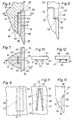
- a tamping pick 1 for track tamping machines shown in FIG. 1 and made of full metal, consists of a - at the upper end with a tamp drive 2 - shown in dash-dotted lines - for the provision and vibration of the tamping tool holder of a tamping unit - pimple shaft 3 with an approximately circular at the lower end, a cross-section having a radius r and a pimple plate 4 formed on the lower end thereof.
- This is made up of a plug connection 7 with a recess or a connection part 6 consisting of a pin 5 shown in side view and a receiving or connecting part 6 arranged on the rear side of the pimple plate 4. Recess releasably attached to the pick shaft 3.
- the pin 5 of the plug-in connection 7 has a step 8 in the side direction - according to the side arrow shown in the drawing - or in the region against the pick plate 4 to the bottom pick shaft.
- the pimple plate 4 is arranged with its upper edge 9 in this stage 8.
- the plug-in connection 7 is formed essentially over the entire height of the pimple plate, in particular up to the wedge-shaped lower edge 10 of the pimple plate 4, the pimple plate 4 with its working surface 11 being essentially flush with the shaft axis 12 of the pimple shaft runs approximately parallel.
- the connecting or receiving part 6 connected to the pimple plate 4 has only a single recess or recess 14 which is in the form of a conical section or in the form of a conical section 13.
- the cone jacket 13 rests on the pimple plate 4 via a parabolic section surface 15 and is welded to it.
- the pin 5 which can be inserted into the recess 14 is conical and is formed with a section surface 17 which corresponds to the inner cone-jacket section 16 and runs approximately parallel to the pin step 8.
- the tapered jacket part 13 of the receiving part 6, with its tapered jacket section-shaped recess 14, has an approximately circular cross section and approximately parallel to the longitudinal direction of the shaft - and preferably at a distance of approximately 1/2 to 3/4 r to the shaft axis 12 or corresponding to the pin step 8 - Running and formed by the pimple plate inner surface or final parabolic section surface 15 is formed.
- the cone jacket part 13 of the connecting or receiving part 6 is designed with its cone jacket axis 18 to the shaft axis 12 at an angle ⁇ of approximately 5 to 15 °, preferably 10 °, inclined towards the pick plate 4.
- the pin 5 can be connectable and detachable to the receiving part 6 by means of a connecting element 21 designed as a wedge 19 or a grooved pin 20, for example with an internal hexagon.
- the conical jacket part 13 has a beveled surface 22 in its lower and outer end region. In this way, the cross-sectional area of the pick plate 4 is reduced in its lower end area, so that the resistance to penetration when the stuffing pick 1 is immersed in the ballast is reduced.
- the circular cross section of the cone shell part 13 forming the connecting or receiving part 6 can be seen, which is welded to the pimple plate 4 via the parabolic section surface 15 .
- the tip of this conical jacket part 13 is designated, which is provided for receiving the tip of the pin 5.
- the notch pin 20 which can be screwed into the conical jacket part 13 by means of a thread, engages with its conical end into a notch (FIG. 1) of the pin 5 of opposite design.
- the cone shell part 13 like the pin 5, is machined to form an exact inner cone shell section 16 or a conical section surface 17 of opposite design by means of machining processes.
- the semi-elliptical surface 22 and the parabolic section surface 15 are then formed by separation. This is welded to the back of the pimple plate 4 with the cone jacket part 13 resting against it.
- the end of the pick shaft 3 designed as a pin 5 is machined to form the step 8 and a surface which preferably runs parallel to the shaft axis 12.
- the pin 5, which may also be provided with an opening for receiving the wedge 19 or a notch for receiving the notch pin 20, is formed exactly opposite to the connecting or receiving part 6.
- the notch pin 20 or the wedge 19 which may be present is loosened or removed. Then the worn pimple plate 4 is released from the pin 4 by hammer blows on the upper edge 9.
- This work can be carried out in an advantageous manner, as can the fastening of new pimple plates 4 with pimple shafts 3 connected to the tamping drives 2.
- the new pimple plate 4 placed on the exposed peg 5 is optionally fastened to the lower edge 10 with light hammer blows - if necessary by screwing in the notch pin 20. It is from Advantage that the flattening of the pin 5 in the area of step 8 automatically positions the pick plate 4 to the pick shaft 3.
- a further embodiment of a pimple plate 24 shown in FIG. 4 with a connecting or receiving part 25 is designed as a special conical jacket part 26. This has on the side opposite the parabolic section surface 27 a further, approximately parabolic section 28, whereby in particular an improved pretension when it is placed on the peg can be achieved for a solid mounting.
- the upper edge 9 of the pimple plate 4 welded to the conical jacket part 13 interacts with the projecting pin step 8 of the pimple shaft 3 serving as a stop. In this way, the reaction or resistance forces acting on the pick plate 4 when the tamping pick 1 is immersed in the ballast - with partial relief of the plug connection 7 - can be transferred directly to the pick shaft 3 via the upper edge 9.
- a tamping pick 29 shown in FIG. 6 has a pick shaft 30 with a longitudinal axis 31 and a pin 32 provided at the lower end of the pick shaft 30 with a wedge-shaped surface 33.
- the pin 32 forms, together with a connecting or receiving part 35 arranged on the rear side of the pick plate 34, a detachable plug connection 36.
- the pin 32 is shown in FIG Adjustment direction according to the arrow shown in the drawing or in the area against the pick plate 34 to the lower pick shaft, forming a step 37, staggered.
- the upper edge 38 of the pick plate 34 is partially arranged in this step 37.
- the plug connection 36 is formed essentially over the entire height of the pick plate 34 up to the wedge-shaped lower edge 39 of the pick plate 34. With its working surface 40, it runs essentially flush or parallel to the pick shaft.
- the connector 36 is made of a connection or.
- Receiving part 35 forming and connected to the back of the pick plate 34, dovetail-shaped connecting web 41 is formed. Whose width is tapered in the direction of the upper edge 38 of the pick plate 34.
- the pin 32 has a receiving groove 42, which is configured opposite to this connecting web 41 and runs in the longitudinal direction of the pin. Since the depth of the receiving groove 42 of the pin 32 is greater than the depth of the connecting web 41, there is a gap 43. The depth of the connecting web 41, which runs perpendicular to the pimple plate, is approximately the same as the thickness of the pimple plate 34.
- the plug connection 36 formed from the connecting web 41 and the receiving groove 42 of the pin 32 is designed such that the rear side 44 of the pick plate 34 bears against the pressing surface 45 of the pin 32 running parallel to the working surface 40.
- the side flanks 46 of the connecting web 41 which form the taper and the undercut form an angle of approximately 45 to 80 °, preferably approximately 60 °, with the rear side 44 of the pick plate 34.
- the worn pimple plate 34 is released from the pin 32 or pimple shaft 30 by hammer blows on the upper edge 38 of the pimple plate 34.
- To fix a new pimple plate 34 it is inserted with its wedge-shaped or dovetail-shaped connecting web 41 into the likewise wedge-shaped and dovetail-shaped receiving groove 42 of the pin 32.
- By strong hammer blows on the lower edge of the pick plate 34 the latter is then brought up in the direction of the pick shaft 30, the upwardly tapering formation of the receiving groove 42 and connecting web 41, with the result that a particularly firm connection between the pick plate 34 and the pin 32 results in a strong clamping effect Has.
- the pick plate 34 is expediently produced by forging, the integrally formed connecting web 41 being reworked with the aid of a machining process.
- the receiving groove 42 in the pin 32 is also machined by means of a machining process.
- a tamping pick 47 shown in FIG. 9 with a pick shaft 49 having a pin 48 and a pick plate 50 has a further embodiment of a plug connection 51.
- a connecting web 52 connected to the rear of the pimple plate 50 is arranged at a distance from the rear of the pimple plate 50 and is projecting above an upper edge 53 of the pimple plate 50.
- a receiving groove 54 of the plug connection 51 arranged in the pin 48 is arranged in the vertical section of a Z-shaped step 55 of the pin 48.
- the lower end region of the pin 48 in turn has a step 56, the pimple plate with its upper edge 53 being partially arranged in this step 56.
- a pimple plate 57 shown in FIGS. 10 and 11 has a connecting or receiving part 58 which is formed from two longitudinal wedge sections 60 which are arranged in mirror image to the longitudinal plane of symmetry 59 of the pimple plate 57 and are spaced apart from one another. These each form an undercut 61 on their outside and are tapered in the direction of the upper edge 62 of the pimple plate 57.
- a protruding projection 64 is provided on the inclined side flank 63. This is designed to snap into a notch of opposite design in the receiving groove of a journal which is also formed opposite to the two longitudinal wedge sections 60.
- a connecting web 65 shown in FIG. 12 of a connecting or receiving part 67 connected to a pick plate 66 has a centrally arranged projection 68 which extends in the longitudinal direction of the web.
- the connecting web 65 for the attachment of weld seams 69 for connection to the pick plate 66 is correctly spaced by this.
- FIG. 13 shows a modification of the tamping pick 29 shown in FIGS. 6 to 8.
- the upper edge 38 of the pick plate 34 lies directly against the step 37 of the pick shaft 30.
- the inclination of the side flanks 46 to one another or the wedge-shaped connecting web 41 is designed in such a way that a sufficient clamping effect in the wedge-shaped receiving groove 42 occurs when the upper edge 38 contacts the step 37. In this way, the reaction or resistance forces occurring when the tamping pick 29 is immersed in the ballast can be transferred directly to the pick shaft 30 and the pin 32 while relieving the plug connection 36.
Landscapes
- Engineering & Computer Science (AREA)
- Architecture (AREA)
- Civil Engineering (AREA)
- Structural Engineering (AREA)
- Machines For Laying And Maintaining Railways (AREA)
- Snaps, Bayonet Connections, Set Pins, And Snap Rings (AREA)
- Packaging Of Machine Parts And Wound Products (AREA)
- Earth Drilling (AREA)
Priority Applications (5)
| Application Number | Priority Date | Filing Date | Title |
|---|---|---|---|
| EP87890274A EP0317692A1 (fr) | 1987-11-26 | 1987-11-26 | Outil de bourrage pour machine à bourrer les voies ferrées |
| US07/210,921 US4922828A (en) | 1987-11-26 | 1988-06-24 | Ballast tamping tool |
| NO88884291A NO884291L (no) | 1987-11-26 | 1988-09-28 | Pakkspett for sporpakkmaskiner. |
| HU885605A HU202599B (en) | 1987-11-26 | 1988-10-27 | Ballast hammer for line-packing machines |
| DD88321541A DD283436A5 (de) | 1987-11-26 | 1988-11-07 | Stopfpickel fuer gleisstopfmaschinen |
Applications Claiming Priority (1)
| Application Number | Priority Date | Filing Date | Title |
|---|---|---|---|
| EP87890274A EP0317692A1 (fr) | 1987-11-26 | 1987-11-26 | Outil de bourrage pour machine à bourrer les voies ferrées |
Publications (1)
| Publication Number | Publication Date |
|---|---|
| EP0317692A1 true EP0317692A1 (fr) | 1989-05-31 |
Family
ID=8198533
Family Applications (1)
| Application Number | Title | Priority Date | Filing Date |
|---|---|---|---|
| EP87890274A Withdrawn EP0317692A1 (fr) | 1987-11-26 | 1987-11-26 | Outil de bourrage pour machine à bourrer les voies ferrées |
Country Status (5)
| Country | Link |
|---|---|
| US (1) | US4922828A (fr) |
| EP (1) | EP0317692A1 (fr) |
| DD (1) | DD283436A5 (fr) |
| HU (1) | HU202599B (fr) |
| NO (1) | NO884291L (fr) |
Cited By (9)
| Publication number | Priority date | Publication date | Assignee | Title |
|---|---|---|---|---|
| AT404038B (de) * | 1993-05-07 | 1998-07-27 | Schwihag Gmbh | Querschwelle zur abstützung von schienen im bereich von weichen |
| RU2219302C1 (ru) * | 2003-03-24 | 2003-12-20 | Конев Владимир Иванович | Подбойка |
| RU2228984C1 (ru) * | 2002-01-18 | 2004-05-20 | Франц Плассер Банбаумашинен-Индустригезельшафт Мбх | Боек шпалоподбойки |
| RU2236494C1 (ru) * | 2003-04-23 | 2004-09-20 | Федеральное государственное унитарное предприятие Всероссийский научно-исследовательский и конструкторско-технологический институт подвижного состава Министерства путей сообщения Российской Федерации | Шпалоподбойка |
| RU2243310C1 (ru) * | 2003-11-19 | 2004-12-27 | Федеральное государственное унитарное предприятие Всероссийский научно-исследовательский и конструкторско-технологический институт подвижного состава | Шпалоподбойка |
| RU2265101C1 (ru) * | 2004-06-08 | 2005-11-27 | Конев Владимир Иванович | Подбойка |
| RU2308560C1 (ru) * | 2006-02-02 | 2007-10-20 | Анатолий Николаевич Шилкин | Подбойка |
| CN103850156A (zh) * | 2012-12-06 | 2014-06-11 | 常州市瑞泰工程机械有限公司 | 内镐臂 |
| RU207113U1 (ru) * | 2021-06-25 | 2021-10-13 | Леонид Михайлович Попко | Подбойка машин для выправки, подбивки и рихтовки железнодорожного пути |
Families Citing this family (14)
| Publication number | Priority date | Publication date | Assignee | Title |
|---|---|---|---|---|
| US5584248A (en) * | 1995-03-22 | 1996-12-17 | Harsco Corporation | Split tool mechanical vibrator |
| AT5201U3 (de) * | 2002-01-17 | 2002-12-27 | Plasser Bahnbaumasch Franz | Stopfpickel |
| AT5704U3 (de) * | 2002-06-28 | 2003-06-25 | Plasser Bahnbaumasch Franz | Stopfpickel und verfahren zu dessen herstellung |
| US7013812B2 (en) * | 2003-11-25 | 2006-03-21 | Ballast Tools, Inc. | Tamping tool |
| US7153129B2 (en) * | 2004-01-15 | 2006-12-26 | John Zink Company, Llc | Remote staged furnace burner configurations and methods |
| US20070186798A1 (en) * | 2006-02-15 | 2007-08-16 | Glenn Gevik | Tamping blade for a railroad tamping machine |
| CN101942788A (zh) * | 2010-08-25 | 2011-01-12 | 西南交通大学 | 具有镐体镐掌复合减振耐磨结构的分体式捣镐及制造工艺 |
| DE202011110462U1 (de) * | 2011-01-19 | 2014-02-28 | Robel Bahnbaumaschinen Gmbh | Handstopfer zum Unterstopfen eines Gleises |
| DE202011103985U1 (de) * | 2011-08-03 | 2011-10-31 | Robel Bahnbaumaschinen Gmbh | Handstopfer zum Unterstopfen eines Gleises |
| USD808443S1 (en) | 2016-03-09 | 2018-01-23 | Good Earth Tools, Inc. | Industrial tool insert |
| USD818007S1 (en) | 2016-04-12 | 2018-05-15 | Good Earth Tools, Inc. | Industrial tool insert |
| USD816724S1 (en) | 2016-04-12 | 2018-05-01 | Good Earth Tools, Inc. | Industrial tool insert |
| DE102017126755A1 (de) * | 2017-11-14 | 2019-05-16 | Alfred Reuter | Stopfpickel |
| WO2020018550A1 (fr) * | 2018-07-16 | 2020-01-23 | Trackmate LLC | Outil de bourrage |
Citations (6)
| Publication number | Priority date | Publication date | Assignee | Title |
|---|---|---|---|---|
| DE2141131A1 (de) * | 1970-08-17 | 1972-02-24 | Canron Ltd.-Canron Limitee, Montreal, Quebec (Kanada) | Stopfwerkzeug einer Gleisstopfmaschine |
| US3826025A (en) * | 1970-03-30 | 1974-07-30 | W Elliott | Ground engaging unit for ballast tamping machines |
| US4062291A (en) * | 1975-02-24 | 1977-12-13 | Vick Edward L | Ballast tamping tool |
| DE2723551A1 (de) * | 1977-05-25 | 1978-11-30 | Bernd Retter | Gleisstopfpickel |
| US4167141A (en) * | 1977-05-11 | 1979-09-11 | Haywood Glen H | Percussive tool with replaceable work bit |
| GB2134576A (en) * | 1983-02-03 | 1984-08-15 | Bofors Ab | Tamping tool |
Family Cites Families (6)
| Publication number | Priority date | Publication date | Assignee | Title |
|---|---|---|---|---|
| US376565A (en) * | 1888-01-17 | Waeeen bickfoed waldbon and geoege gael bollee | ||
| US2666272A (en) * | 1950-10-16 | 1954-01-19 | Earth Equipment Corp | Excavator bucket tooth |
| US2990633A (en) * | 1953-12-09 | 1961-07-04 | Lesher W Van Buskirk | Dipper teeth |
| US3729055A (en) * | 1971-03-24 | 1973-04-24 | G Burridge | Tamper bar for a tamping machine |
| DE2849951A1 (de) * | 1978-11-17 | 1980-05-29 | Bernd Retter | Stopfpickel fuer eine gleisstopfmaschine |
| US4606275A (en) * | 1984-10-25 | 1986-08-19 | Grant Michael R | Tamping tools |
-
1987
- 1987-11-26 EP EP87890274A patent/EP0317692A1/fr not_active Withdrawn
-
1988
- 1988-06-24 US US07/210,921 patent/US4922828A/en not_active Expired - Fee Related
- 1988-09-28 NO NO88884291A patent/NO884291L/no unknown
- 1988-10-27 HU HU885605A patent/HU202599B/hu not_active IP Right Cessation
- 1988-11-07 DD DD88321541A patent/DD283436A5/de not_active IP Right Cessation
Patent Citations (6)
| Publication number | Priority date | Publication date | Assignee | Title |
|---|---|---|---|---|
| US3826025A (en) * | 1970-03-30 | 1974-07-30 | W Elliott | Ground engaging unit for ballast tamping machines |
| DE2141131A1 (de) * | 1970-08-17 | 1972-02-24 | Canron Ltd.-Canron Limitee, Montreal, Quebec (Kanada) | Stopfwerkzeug einer Gleisstopfmaschine |
| US4062291A (en) * | 1975-02-24 | 1977-12-13 | Vick Edward L | Ballast tamping tool |
| US4167141A (en) * | 1977-05-11 | 1979-09-11 | Haywood Glen H | Percussive tool with replaceable work bit |
| DE2723551A1 (de) * | 1977-05-25 | 1978-11-30 | Bernd Retter | Gleisstopfpickel |
| GB2134576A (en) * | 1983-02-03 | 1984-08-15 | Bofors Ab | Tamping tool |
Cited By (10)
| Publication number | Priority date | Publication date | Assignee | Title |
|---|---|---|---|---|
| AT404038B (de) * | 1993-05-07 | 1998-07-27 | Schwihag Gmbh | Querschwelle zur abstützung von schienen im bereich von weichen |
| RU2228984C1 (ru) * | 2002-01-18 | 2004-05-20 | Франц Плассер Банбаумашинен-Индустригезельшафт Мбх | Боек шпалоподбойки |
| RU2219302C1 (ru) * | 2003-03-24 | 2003-12-20 | Конев Владимир Иванович | Подбойка |
| RU2236494C1 (ru) * | 2003-04-23 | 2004-09-20 | Федеральное государственное унитарное предприятие Всероссийский научно-исследовательский и конструкторско-технологический институт подвижного состава Министерства путей сообщения Российской Федерации | Шпалоподбойка |
| RU2243310C1 (ru) * | 2003-11-19 | 2004-12-27 | Федеральное государственное унитарное предприятие Всероссийский научно-исследовательский и конструкторско-технологический институт подвижного состава | Шпалоподбойка |
| RU2265101C1 (ru) * | 2004-06-08 | 2005-11-27 | Конев Владимир Иванович | Подбойка |
| RU2308560C1 (ru) * | 2006-02-02 | 2007-10-20 | Анатолий Николаевич Шилкин | Подбойка |
| CN103850156A (zh) * | 2012-12-06 | 2014-06-11 | 常州市瑞泰工程机械有限公司 | 内镐臂 |
| CN103850156B (zh) * | 2012-12-06 | 2015-10-28 | 常州市瑞泰工程机械有限公司 | 内镐臂 |
| RU207113U1 (ru) * | 2021-06-25 | 2021-10-13 | Леонид Михайлович Попко | Подбойка машин для выправки, подбивки и рихтовки железнодорожного пути |
Also Published As
| Publication number | Publication date |
|---|---|
| NO884291L (no) | 1989-05-29 |
| US4922828A (en) | 1990-05-08 |
| HU202599B (en) | 1991-03-28 |
| HUT52583A (en) | 1990-07-28 |
| NO884291D0 (no) | 1988-09-28 |
| DD283436A5 (de) | 1990-10-10 |
Similar Documents
| Publication | Publication Date | Title |
|---|---|---|
| EP0317692A1 (fr) | Outil de bourrage pour machine à bourrer les voies ferrées | |
| EP0184209B1 (fr) | Montage pour dent d'excavatrice | |
| DE3427610C2 (de) | Verschleißteilsystem für Erdbewegungsmaschinen | |
| DE69614634T2 (de) | Einsatz-Element zur Aufnahme wenigstens eines Fräswerkzeuges, das auf Frästrommeln von Arbeitsmaschinen zur Entfernung von Böden anzubringen ist | |
| DE2921175A1 (de) | Schraemmaschine | |
| DE3339558A1 (de) | Gewinnungseinrichtung mit dreh-kippmeissel und geschlossener meisseltasche | |
| DE3403459C2 (de) | Gleisstopfwerkzeug und Verfahren zu dessen Herstellung | |
| DE3004568A1 (de) | Schneidwerkzeug mit einem auswechselbaren hartmetall-schneideinsatz | |
| DE10044369C2 (de) | Schnellwechselhaltersystem für Werkzeuge auf Walzen | |
| DE8320045U1 (de) | Stahlspaten fuer schlaghaemmer | |
| DE102005017760A1 (de) | Schnellwechselhaltersystem | |
| DE2141131A1 (de) | Stopfwerkzeug einer Gleisstopfmaschine | |
| DE2723551A1 (de) | Gleisstopfpickel | |
| DE3300422A1 (de) | Werkzeug und werkzeughalterung fuer erdbearbeitungsmaschinen | |
| EP0439821A1 (fr) | Couronne de coupe pour tubes de forage avec dents facilement échangeables | |
| DE3434348C2 (de) | Halterung für Schrämmeißel bei Kohlengewinnungsmaschinen | |
| DE2841679A1 (de) | Auswechselbare bohrkrone fuer einen bei allen gesteinsarten anwendbaren gesteindrehschlagbohrer und bohrhammer | |
| EP0436859A2 (fr) | Coffrage pour la fabrication de traverses en béton précontraint avec ancrage immédiat | |
| DE3442747A1 (de) | Aus zahn und adapter bestehender werkzeugsatz | |
| DE2656795B2 (de) | Schlagwerkzeug zum Einsetzen in einen Abbau- bzw. Aufbruchhammer | |
| DE3242144C2 (de) | Dreh-Kippmeißel | |
| DE3737276A1 (de) | Stopfpickel fuer eine gleisstopfmaschine | |
| EP0223896A2 (fr) | Elément coupant d'une chaîne de havage | |
| DE19949663B4 (de) | Brechrotor | |
| DE2855577A1 (de) | Fraesmeissel fuer eine fraes- oder schraemmeinrichtung |
Legal Events
| Date | Code | Title | Description |
|---|---|---|---|
| PUAI | Public reference made under article 153(3) epc to a published international application that has entered the european phase |
Free format text: ORIGINAL CODE: 0009012 |
|
| 17P | Request for examination filed |
Effective date: 19881103 |
|
| AK | Designated contracting states |
Kind code of ref document: A1 Designated state(s): AT DE ES FR GB IT SE |
|
| 17Q | First examination report despatched |
Effective date: 19910429 |
|
| STAA | Information on the status of an ep patent application or granted ep patent |
Free format text: STATUS: THE APPLICATION IS DEEMED TO BE WITHDRAWN |
|
| 18D | Application deemed to be withdrawn |
Effective date: 19910601 |
|
| RIN1 | Information on inventor provided before grant (corrected) |
Inventor name: THEURER, JOSEF Inventor name: HANSMANN, JOHANN |