EP0436859A2 - Coffrage pour la fabrication de traverses en béton précontraint avec ancrage immédiat - Google Patents
Coffrage pour la fabrication de traverses en béton précontraint avec ancrage immédiat Download PDFInfo
- Publication number
- EP0436859A2 EP0436859A2 EP90123890A EP90123890A EP0436859A2 EP 0436859 A2 EP0436859 A2 EP 0436859A2 EP 90123890 A EP90123890 A EP 90123890A EP 90123890 A EP90123890 A EP 90123890A EP 0436859 A2 EP0436859 A2 EP 0436859A2
- Authority
- EP
- European Patent Office
- Prior art keywords
- anchor plate
- wire
- formwork
- threshold
- tensioning
- Prior art date
- Legal status (The legal status is an assumption and is not a legal conclusion. Google has not performed a legal analysis and makes no representation as to the accuracy of the status listed.)
- Withdrawn
Links
Images






Classifications
-
- B—PERFORMING OPERATIONS; TRANSPORTING
- B28—WORKING CEMENT, CLAY, OR STONE
- B28B—SHAPING CLAY OR OTHER CERAMIC COMPOSITIONS; SHAPING SLAG; SHAPING MIXTURES CONTAINING CEMENTITIOUS MATERIAL, e.g. PLASTER
- B28B23/00—Arrangements specially adapted for the production of shaped articles with elements wholly or partly embedded in the moulding material; Production of reinforced objects
- B28B23/02—Arrangements specially adapted for the production of shaped articles with elements wholly or partly embedded in the moulding material; Production of reinforced objects wherein the elements are reinforcing members
- B28B23/04—Arrangements specially adapted for the production of shaped articles with elements wholly or partly embedded in the moulding material; Production of reinforced objects wherein the elements are reinforcing members the elements being stressed
- B28B23/06—Arrangements specially adapted for the production of shaped articles with elements wholly or partly embedded in the moulding material; Production of reinforced objects wherein the elements are reinforcing members the elements being stressed for the production of elongated articles
Definitions
- the invention relates to a formwork for producing prestressed concrete sleepers with an immediate bond, as described in the preamble of claim 1.
- the lost anchor plates each anchor, for example, two or four rods and have on their side facing away from the threshold means for connecting to tension rods, to which a clamping press can be attached.
- the smooth tension wires are cut to the desired length, passed through bores in the anchor plate with a slightly larger diameter than that of the rod cross-section, and then provided at their ends with swaged heads that anchor the tension wires in the anchor plate.
- the bundle of tensioning wires with anchor plates prepared in this way is installed in the sleeper formwork and prestressed against the end faces of the formwork. Then concrete is poured into the formwork and after it has hardened sufficiently, the anchors are loosened and the tension rods are unscrewed from the anchor plate and removed. This transfers the pre-tension from the tension wires to the concrete of the sleeper via the anchor plates.
- the threshold can be lifted out of the formwork.
- the anchor plates are lost.
- the former production method A it is only possible to pretension a limited number of tension wires.
- the points of attack for the drawing heads at the rod ends are relocated in front of the level of the formwork into the concrete of the sleeper, so that the sleeper is unimpeded after the concrete has hardened and the pulling heads removed from the threshold tension wire ends protruding into the formwork can be lifted out of the formwork.
- These sinking constructions do not allow the use of conventional bundle presses.
- the pulling head to be attached to each individual tension wire has a minimum size, which requires a corresponding minimum distance to the next pulling head. This minimum distance corresponds to a maximum number of tension wires assigned to the predetermined end face of the threshold, which can be arranged on this end face.
- Manufacturing method B uses smooth reinforcement bars and therefore cannot apply the prestressing forces to the threshold concrete via composite.
- the tension wire anchors become part of the threshold and are therefore lost.
- the loss of the anchor plates means that sleeper production becomes more expensive.
- the wire heads must also be pushed onto the bars mounted in the reinforcement cage for at least one anchoring side, which represents a considerable hindrance to this operation.
- the tension wires are temporarily anchored in an anchor plate, which - as is known from manufacturing process B - has means for fastening a tension rod to which the Clamping press can be used.
- the anchor plate enables the arrangement of practically any number of tensioning wires in the sleeper and their simultaneous prestressing with a press in one operation, without the need for a pulling head which requires space at each tensioning wire end.
- the anchor plate is recovered in order to economically exploit the property of the ribbed tensioning wire in introducing its tension into the threshold concrete via adhesive bond.
- the subclaims relate to configurations of the formwork by means of different designs of the anchor plate forming part of the end formwork, which allow the anchor plates to be recovered after the concrete of the threshold has sufficiently hardened and after the tension member for the tensioning press has been released from the anchor plate.
- the anchoring devices in the formwork according to claims 6 to 14 additionally solve the task of being able to emerge the wire heads on both tension wire ends independently of the anchoring in the anchor plate and of the assembly of the tensioning bundle. This significantly simplifies the upsetting process and the assembly of the tension bundle in the formwork.
- the tension wire anchors for the recovery of the anchor plates can be released non-destructively in these devices.
- the claims 15 to 20 specify expedient shapes of the anchor plate, which should facilitate the removal of the threshold and the recovery of the anchor plate.
- the anchoring device comprises the anchor plate 2 with bushings 3 for the tensioning wires 5.
- the tie rod 4 is detachably connected to the anchor plate 2. It can be connected to it via a bore 40 arranged in the center of gravity of the tensioning wires 5, for example by means of a threaded connection.
- the tensioning wires 5 are anchored on the side of the anchor plate 2 facing away from the threshold 7 by upset wire heads 6.
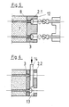
- An intermediate layer 9 with reduced strength or a flexible layer 10 can be arranged between the anchor plate 2 and the end face 8 of the threshold 7.
- the intermediate layer 9 is intended to reduce the cutting effort when severing the wire heads according to claim 4. Due to the flexibility of the layer 10, the anchor plate 2 can be pressed against the end face 8 of the threshold 7. The resulting gap 11 between the anchor plate 2 and the wire head makes a method according to claim 5 or a device according to claim 10 applicable.
- FIG. 5 shows a milling cutter with which the wire heads 6 are milled.
- tools 14 that are moved in slots 13 of an anchor plate 2.2 separate the wire heads 6.
- the wire heads 6 are blasted off by sudden heating with an arc 15.
- FIGS. 8 to 16 show examples of anchor plates in which the tension wire anchorings can be detached from the threshold without being destroyed.
- the anchor plate 2.3 according to FIG. 8 has keyhole-shaped feedthroughs 16, consisting of a bore 17 and a slot 18 that widens the bore 17 in one direction.
- the diameter of the bore 17 is slightly larger than the diameter of the wire head 6, the width of the slot 18 is slightly wider than the thickness of the tension wire 5.
- the centers of the bores 17 and the axes of the slots 18 have at least one circle 19 around as a common geometric location the common pivot point 20.
- the prestressing reinforcement is preassembled by inserting the wire heads 6 through the bores 17 and pushing the shafts of the tensioning wires 5 into the slots 18.
- the wire heads 6 When the tensioning wires 5 are tensioned after the tensioning reinforcement has been installed in the formwork, the wire heads 6 rest on the edges of the slots 18 and anchor the tension wires 5. After striking the concrete threshold, pressing the plate - for example if an elastic layer 10 is provided - loosens the contact pressure of the wire heads 6 in the slots 18, and the plate can be rotated and released in the direction of the arrow. Correspondingly, the wire heads 6 are anchored in the anchor plate 2.4 according to FIG. 9 and, after stripping the threshold, are loosened again by pushing the shafts of the tension wires 5 into the slots 18, 21 by pressing down the anchor plate 2.4 and moving them upward.
- FIGS. 10 and 11 instead of an anchor plate with keyhole-shaped bushings 16, according to FIGS. 10 and 11, anchor plates 2.5 with bores 22 which are round in cross section and have a diameter slightly larger than the diameter of the wire head 6, and fork-shaped disks 23 provided with a slot 24 for anchoring the tension wires 5 to be used.
- the slot 24 of the disk 23 encompasses the shaft of the tensioning wire 5 behind the wire head 6.
- FIG. 11 also shows the example of a bushing 3.4 with bushing 3.4 that widens conically on the threshold side to a larger part 27 of the plate thickness.
- the tension wires 5 are by conical anchoring parts 25, which are self-locking around their shaft. If the wire head 6 is relieved by pressing the anchor plate 2.6 against a resilient layer 10, springs 39 press the anchoring parts 25 apart and the anchor plate 2.6 can be pulled off over the wire heads.
- the tension wire 5 protrudes as little as possible from the end face 8 of the finished sleeper 7 after the anchor plate 2 has been released.
- This is achieved by countersinking the wire heads 6 on the side of the anchor plate facing away from the threshold 7. Sufficiently, this is done in the anchor plate 2.1, for example in FIGS. 5 and 7, where the wire heads 6 have to be removed to release the anchor plate.
- an even deeper depression of the wire head 6 is expedient in order to make the wire head 6 also disappear in the plane of the end face 8 of the threshold 7.
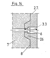
- anchor plates 2.7 according to FIG. 14 which have templates 26 on the bushings 3.3 on the side facing the concrete. By means of the template 26, the shoulder for the clamping head anchoring can be sunk in the implementation 3.3 beyond the thickness of the anchor plate 2.7.
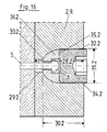
- a bushing 28.1 or 28.2 is provided in the anchor plate 2.8 or 2.9 for each tensioning wire 5, the lower section 29.1 or 29.2 facing the threshold 7 has a clear diameter which is slightly larger than the outer diameter of the wire head 6, and whose outer section 30.1 or 30.2 facing away from the threshold 7 is considerably widened to accommodate multi-part wire head anchorings 31.1 or 31.2 and is provided with an internal thread 32.1 or 32.2.
- the wire head anchoring 31.1 or 31.2 comprises the chuck 36.1 or 36.2 consisting of several segments, which rests on the shoulder 33.1 or 33.2 formed by the cross-sectional jump of the bushing 28.1 or 28..2 and the packer 34.1 or 34.2.
- the packer 34.1 or 34.2 has an external diameter and an external thread which corresponds to the internal diameter and internal thread of the outer section 30.1 or 30.2 of the bushing 28.1 or 28.2. Its head 35.1 or 35.2 corresponds to the shape of the chuck 36.1 or 36.2.
- the chuck 36.1 or 36.2 is pressed firmly against the shaft of the tensioning wire 5 inserted through the lower section 29.1 or 29.2 of the leadthrough 28.1 or 28.2 immediately behind the wire head 6 by screwing in the packer 34.1 or 34.2.
- the tension wire anchoring and thus the anchor plate 2.8 or 2.9 can be released again.
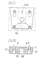
- the anchor plate 2.10 shows a suitable trapezoidal shape in the view according to FIG. 17.
- the tapering of the anchor plate 2.11 in the cross section according to FIG. 18, which is proposed in cross section after the side 38 facing away from the end face 8 of the threshold 7, serves to compensate for a possibly obstructing inclined position of the anchor plate when Clamping process.
- An anchor plate 2.12 according to claim 13 with a conical template 26 is provided with holes 40 perpendicular to the tension wire axis.
- Tubes 41 are rotatably arranged in the bores 40, for example by means of a key which engages in an Allen key 44 at their upper end.
- Each tube 41 has an opening 42 at the level of the section with a tensioning wire axis, with an adjoining slot 43 extending perpendicular to the axis of rotation of the tube 41 on the tube jacket.
- the wire head 6 of the tension wire 5 is pushed into the interior of the tube 41 through a bore 39 arranged in the axis of the tension wire 5 and the approximately 42 opening lying behind it, and by rotating the tube so that the slot 43 is in front of the wire head 6 slides over the shaft of the tensioning wire, anchored in the anchor plate 2.12.
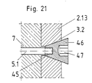
- the anchor plate 2.12 in FIG. 21 offers a further variant for anchoring.
- the tension wire 5.1 is provided with a threaded head 45 which anchors by means of a threaded spindle 46 which rests in a conical passage 3.2 corresponding to the shape of the spindle.
- the threaded spindle 46 has means 47, by means of which it can be screwed onto the threaded head 45.
Landscapes
- Engineering & Computer Science (AREA)
- Manufacturing & Machinery (AREA)
- Chemical & Material Sciences (AREA)
- Ceramic Engineering (AREA)
- Mechanical Engineering (AREA)
- Manufacturing Of Tubular Articles Or Embedded Moulded Articles (AREA)
Applications Claiming Priority (2)
| Application Number | Priority Date | Filing Date | Title |
|---|---|---|---|
| DE4000729 | 1990-01-12 | ||
| DE4000729 | 1990-01-12 |
Publications (2)
| Publication Number | Publication Date |
|---|---|
| EP0436859A2 true EP0436859A2 (fr) | 1991-07-17 |
| EP0436859A3 EP0436859A3 (en) | 1992-03-04 |
Family
ID=6397950
Family Applications (1)
| Application Number | Title | Priority Date | Filing Date |
|---|---|---|---|
| EP19900123890 Withdrawn EP0436859A3 (en) | 1990-01-12 | 1990-12-12 | Shuttering for making prestressed concrete sleepers with immediate anchoring |
Country Status (3)
| Country | Link |
|---|---|
| US (1) | US5196209A (fr) |
| EP (1) | EP0436859A3 (fr) |
| ES (1) | ES2023104A4 (fr) |
Cited By (3)
| Publication number | Priority date | Publication date | Assignee | Title |
|---|---|---|---|---|
| DE4203223A1 (de) * | 1991-02-07 | 1992-08-13 | Wayss & Freytag Ag | Spannstabverankerung fuer betonfertigteile |
| EP1360397B2 (fr) † | 2001-02-14 | 2009-11-11 | Max Bögl Bauunternehmung GmbH & Co. KG | Procede et palette pour produire une piece prefabriquee en beton precise |
| CN111618976A (zh) * | 2020-05-13 | 2020-09-04 | 中铁六局集团有限公司 | 装配式建筑预制构件固定模台施工工法 |
Families Citing this family (3)
| Publication number | Priority date | Publication date | Assignee | Title |
|---|---|---|---|---|
| US5366672A (en) * | 1993-03-18 | 1994-11-22 | Erico International Corporation | Method of forming concrete structures with a grout splice sleeve which has a threaded connection to a reinforcing bar |
| DE102012217823A1 (de) * | 2012-09-28 | 2014-04-03 | Harsco Infrastructure Services Gmbh | Wandschalung mit Abdichtungssystem |
| JP6384959B2 (ja) * | 2015-03-11 | 2018-09-05 | 日本コンクリート工業株式会社 | コンクリート製品製造装置およびコンクリート製品の製造方法 |
Family Cites Families (15)
| Publication number | Priority date | Publication date | Assignee | Title |
|---|---|---|---|---|
| DE578768C (de) * | 1931-06-24 | 1933-06-16 | Otto Gloeser | Vorrichtung zum Herstellen von Eisenbetonbauteilen |
| US2655708A (en) * | 1952-09-23 | 1953-10-20 | Hector X Eschenbrenner | Method and apparatus for molding cementitious bodies |
| GB751631A (en) * | 1954-02-23 | 1956-07-04 | Concrete Patents Ltd | An improved method of tensioning and anchoring wires |
| US2867884A (en) * | 1954-09-07 | 1959-01-13 | Prestressing Inc | Post-tensioned anchor device |
| US3236486A (en) * | 1958-02-17 | 1966-02-22 | Allen Form Corp | Waler brackets |
| US3427772A (en) * | 1966-09-06 | 1969-02-18 | George W Williams | Apparatus for post-tensioning and interconnecting re-enforcing wires using key hole anchor plates in a concrete structure |
| FR1528919A (fr) * | 1967-05-05 | 1968-06-14 | Dispositif d'ancrage de fils en acier à haute limite élastique, utilisable notamment dans la technique du béton pré-contraint | |
| US3462106A (en) * | 1967-10-11 | 1969-08-19 | Frank E Buyken | Waler bracket |
| US3583047A (en) * | 1969-08-20 | 1971-06-08 | Nippon Concrete Ind Co Ltd | Apparatus for manufacturing prestressed concrete poles,piles and the like |
| US3734453A (en) * | 1970-12-18 | 1973-05-22 | A Bailey | Tie rod assembly |
| AU473750B2 (en) * | 1973-04-09 | 1974-10-10 | Nippon Concrete Kogyo K.K. | Method of manufacturing prestressed concrete poles, piles andthe like |
| SE376638B (fr) * | 1973-05-21 | 1975-06-02 | L Wahman | |
| US3962786A (en) * | 1974-12-30 | 1976-06-15 | Nippon Concrete Industries Co. Ltd. | Apparatus for cutting rivets of tensioned reinforcement in the process of manufacturing concrete products |
| FR2498976A1 (fr) * | 1981-02-04 | 1982-08-06 | Borcoman Mircea | Methode, dispositifs, structures porteuses de moules et installations pour l'amelioration de l'efficacite des procedes pour la fabrication des produits en beton precontraint |
| DE3931201C1 (en) * | 1989-09-19 | 1990-11-22 | Wayss & Freytag Ag, 6000 Frankfurt, De | Concrete railway sleepers mfr. - uses moving frame mechanism which releases each sleeper immediately |
-
1990
- 1990-12-12 EP EP19900123890 patent/EP0436859A3/de not_active Withdrawn
- 1990-12-12 ES ES90123890T patent/ES2023104A4/es active Pending
-
1991
- 1991-01-14 US US07/641,157 patent/US5196209A/en not_active Expired - Lifetime
Cited By (3)
| Publication number | Priority date | Publication date | Assignee | Title |
|---|---|---|---|---|
| DE4203223A1 (de) * | 1991-02-07 | 1992-08-13 | Wayss & Freytag Ag | Spannstabverankerung fuer betonfertigteile |
| EP1360397B2 (fr) † | 2001-02-14 | 2009-11-11 | Max Bögl Bauunternehmung GmbH & Co. KG | Procede et palette pour produire une piece prefabriquee en beton precise |
| CN111618976A (zh) * | 2020-05-13 | 2020-09-04 | 中铁六局集团有限公司 | 装配式建筑预制构件固定模台施工工法 |
Also Published As
| Publication number | Publication date |
|---|---|
| EP0436859A3 (en) | 1992-03-04 |
| ES2023104A4 (es) | 1992-01-01 |
| US5196209A (en) | 1993-03-23 |
Similar Documents
| Publication | Publication Date | Title |
|---|---|---|
| EP1105597B1 (fr) | Dispositif permettant de fixer en terre des barres, des poteaux, des mats, etc., et procede de fabrication dudit dispositif | |
| EP0211256A2 (fr) | Dispositif d'ancrage dans le béton pour charges lourdes | |
| EP0317692A1 (fr) | Outil de bourrage pour machine à bourrer les voies ferrées | |
| EP2060703A1 (fr) | Tirant de coffrage | |
| DE3004568A1 (de) | Schneidwerkzeug mit einem auswechselbaren hartmetall-schneideinsatz | |
| DE3721446C2 (de) | Stanzwerkzeug | |
| DE2925526A1 (de) | Befestigungselement und zugehoeriges werkzeug | |
| EP0436859A2 (fr) | Coffrage pour la fabrication de traverses en béton précontraint avec ancrage immédiat | |
| EP2882557B1 (fr) | Dispositif de sectionnement de câbles de haubanage | |
| DE10114929C2 (de) | Abstandshalter für nicht-tragfähige Vorsatzschalen und Verfahren zur Befestigung | |
| DE3539612C1 (de) | Vorrichtung zur Erzielung eines loesbaren Presssitzes zwischen einem Bauteil mit zylindrischer Bohrung und einem in diese Bohrung eingefuehrten Bauteil | |
| DE2656795B2 (de) | Schlagwerkzeug zum Einsetzen in einen Abbau- bzw. Aufbruchhammer | |
| EP3330448A1 (fr) | Dispositif et procédé de raccordement de deux composants dans une orientation déterminée relative ainsi que construction en béton | |
| EP1847666A1 (fr) | Dispositif d'ancrage pour lier des planches de coffrage | |
| DE19907475C1 (de) | Ankerschiene für die Bautechnik mit mittels Abstreifkragen fixierten Ankern | |
| DE4236159C2 (de) | Platzhalter für Schienenbefestigung | |
| EP4301991B1 (fr) | Procédé et système de nivellement d'un élément de fixation à ancrer dans un sous sol | |
| DE2322991A1 (de) | Verankerung fuer seile oder dergleichen, insbesondere fuer die spannglieder im spannbeton-bau | |
| DE3503186C2 (fr) | ||
| DE10258435B4 (de) | Verankerungselement | |
| DE2424534C3 (de) | Befestigungsvorrichtung für Schwellenschrauben o.dgl | |
| DE3242144A1 (de) | "gewinnungseinrichtung mit dreh-kippmeissel" | |
| EP3730263B1 (fr) | Procédé de fabrication d'une pluralité d'éléments coulée de béton en béton précontraint | |
| DE202017101599U1 (de) | Nivellierungshilfe und Nivellierungsvorrichtung für plattenförmige Boden- oder Wandverkleidungen | |
| DE202023103836U1 (de) | Positioniervorrichtung |
Legal Events
| Date | Code | Title | Description |
|---|---|---|---|
| PUAI | Public reference made under article 153(3) epc to a published international application that has entered the european phase |
Free format text: ORIGINAL CODE: 0009012 |
|
| ITCL | It: translation for ep claims filed |
Representative=s name: LENZI & C. |
|
| AK | Designated contracting states |
Kind code of ref document: A2 Designated state(s): AT BE CH DE ES FR GB IT LI NL |
|
| GBC | Gb: translation of claims filed (gb section 78(7)/1977) | ||
| EL | Fr: translation of claims filed | ||
| TCNL | Nl: translation of patent claims filed | ||
| REG | Reference to a national code |
Ref country code: ES Ref legal event code: BA2A Ref document number: 2023104 Country of ref document: ES Kind code of ref document: A4 |
|
| PUAL | Search report despatched |
Free format text: ORIGINAL CODE: 0009013 |
|
| AK | Designated contracting states |
Kind code of ref document: A3 Designated state(s): AT BE CH DE ES FR GB IT LI NL |
|
| STAA | Information on the status of an ep patent application or granted ep patent |
Free format text: STATUS: THE APPLICATION HAS BEEN WITHDRAWN |
|
| 18W | Application withdrawn |
Withdrawal date: 19921009 |