EP0317762A2 - Méthode et dispositif pour la commande du papier d'une imprimante - Google Patents
Méthode et dispositif pour la commande du papier d'une imprimante Download PDFInfo
- Publication number
- EP0317762A2 EP0317762A2 EP88117397A EP88117397A EP0317762A2 EP 0317762 A2 EP0317762 A2 EP 0317762A2 EP 88117397 A EP88117397 A EP 88117397A EP 88117397 A EP88117397 A EP 88117397A EP 0317762 A2 EP0317762 A2 EP 0317762A2
- Authority
- EP
- European Patent Office
- Prior art keywords
- paper web
- paper
- printer
- motor
- providing
- Prior art date
- Legal status (The legal status is an assumption and is not a legal conclusion. Google has not performed a legal analysis and makes no representation as to the accuracy of the status listed.)
- Withdrawn
Links
Images


Classifications
-
- B—PERFORMING OPERATIONS; TRANSPORTING
- B41—PRINTING; LINING MACHINES; TYPEWRITERS; STAMPS
- B41J—TYPEWRITERS; SELECTIVE PRINTING MECHANISMS, i.e. MECHANISMS PRINTING OTHERWISE THAN FROM A FORME; CORRECTION OF TYPOGRAPHICAL ERRORS
- B41J15/00—Devices or arrangements of selective printing mechanisms, e.g. ink-jet printers or thermal printers, specially adapted for supporting or handling copy material in continuous form, e.g. webs
- B41J15/04—Supporting, feeding, or guiding devices; Mountings for web rolls or spindles
-
- B—PERFORMING OPERATIONS; TRANSPORTING
- B41—PRINTING; LINING MACHINES; TYPEWRITERS; STAMPS
- B41J—TYPEWRITERS; SELECTIVE PRINTING MECHANISMS, i.e. MECHANISMS PRINTING OTHERWISE THAN FROM A FORME; CORRECTION OF TYPOGRAPHICAL ERRORS
- B41J3/00—Typewriters or selective printing or marking mechanisms characterised by the purpose for which they are constructed
- B41J3/60—Typewriters or selective printing or marking mechanisms characterised by the purpose for which they are constructed for printing on both faces of the printing material
Definitions
- This invention relates to printers and more particularly to paper tension control in a printer using a roll of paper to print on.
- Paper handling mechanisms for high-speed sheet paper printers are typically very complex and very expensive.
- some high-speed prior art printers utilize a roll of paper that passes through the printer mechanisms as one continuous web and, after printing is accomplished, the paper is cut into sheets and is output either directly from the printer or is output via prior art collator mechanisms.
- There have been problems with these prior art roll paper printers in that the tension on the paper web is varied throughout the printer mechanisms caused by the mechanisms starting and stopping, and by different pressures being applied to the paper by drive rollers. The result has been variable elongation of the paper web.
- the result of variable elongation of the paper web with two sided printing being performed is a misregistration of the print on both sides of the paper.
- the above stated needs of the prior art are met by the novel printer roll paper control apparatus and method disclosed and claimed herein.
- the basic printer in which the invention is used has a relatively simple paper handling mechanism, is modular, and can be easily and quickly converted from a one-sided printer to a two-sided printer at minimal expense.
- this basic printer performs front and backside printing at the same time to speed up the printing process while avoiding the need for a complex paper handling mechanism to perform two-sided printing as is required in the prior art.
- the novel paper control apparatus has paper travel speed sensors, load sensors and control circuitry that regulate power being applied to drive and tension motors throughout the printer mechanisms to keep tension on the paper web relatively constant throughout.
- the constant tension stabilizes forces on the paper web and thereby stabilizes elongation of the paper web. This improves front to back print registration, and vertical print position registration to provide two sided copies that are consistently as good as those obtained from a sheet paper printer.
- FIG. 1 a front view of a printer housing 10 in which are located a number of modules that make up the printer.
- a power supply 11 that is connected to AC power (not shown) and provides the DC and AC power to all the other modules inside of housing 10.
- Supply 11 may conveniently be made up of a number of smaller modular power supplies (not shown) that may be easily accessed for maintenance or replacement. The power supply is heavy and by mounting it in the bottom of housing 10 the center of gravity of the printer is lowered for safety considerations.
- Module 12 mounted at the top left of housing 10 where it is easily accessible from the top for testing, maintenance and replacement.
- Module 12 is not shown in any detail since its function and makeup are well known in the art, but advantageously uses plug in printed circuit cards. The printed circuit cards are easily and quickly replaced to speed up maintenance and repairs, and also permits easy, fast upgrading of the electronics.
- Electronics module 12 has the logic that basically controls all the other modules inside of housing 10, and receives, stores, and initially processes the electronic signals that indicate the alphanumeric and other images to be printed.
- the printer described herein preferably uses a roll of paper 13 that is to be printed on, rather than using discrete sheets of paper from a sheet feeder.
- a roll of paper 13 simplifies the handling of paper web 32 between the modules inside of printer housing 10.
- paper roll 13 is shown mounted external to printer housing 10 for ease of replacing the paper roll. External mounting is the preferred embodiment of the invention and permits large diameter paper rolls to be used, but paper roll 13 may alternately be mounted internal to printer housing 10. With the alternate internal mounting only smaller diameter rolls of paper may typically be used.
- Electrographic printing mechanisms are basically comprised of a copier mechanism which uses a special coated drum on which the image to be printed is created as an electrostatic image which is then developed using a dry or wet toner. The toner image is then transferred to sheet or roll paper passing through the mechanism and is then fixed thereon by a number of means including heat.
- a laser beam is deflected over the surface of the drum responsive to electronic signals which indicate the alphanumeric and other images that are to be printed on the paper.
- electronic signals which indicate the alphanumeric and other images that are to be printed on the paper.
- printer housing 10 Mounted inside of printer housing 10 are also other well known modules needed to handle roll paper. They are a perforator 16 used to perforate the paper at the point at which a sheet is to be formed, a punch mechanism 17 used to punch round holes through the edge of each copy sheet for mounting the sheets in three ring binders, a drive station 18, and a paper cutter 19 for cutting the roll paper into individual sheets. Modules 16, 17, 18 and 19 are preferably mounted on a subchassis 31 for ease of removal for maintenance and replacement. Individual cut sheets of paper printed on one or both sides leave cutter 19, exit printer housing 10 at exit 26 and are collated or otherwise stacked by an external stacking assembly 34 in a manner well known in the art.
- paper web 32 from paper roll 13 first passes around a roller 36 at the end of splice station 37.
- Station 37 is the point at which the paper at the beginning of a new roll paper is spliced to the end of a just depleted roll of paper (not shown). This is done so that the new roll of paper need not be rerouted through the mechanisms inside printer 10.
- Paper web 32 then enters the printer housing 10 and passes over roller 35.
- an end of roll indication is detected by a sensor (not shown) which provides a signal to electronics module 12 that causes the printer to stop, and a paper roll replace signal to be given until an empty paper roll 13 is replaced with a new roll of paper.
- the end of the depleted roll is spliced to the beginning of a new roll at splice station 37 as previously mentioned.
- the paper web 32 from roll 13 enters the first modular printer mechanism 14 at input 27 and alphanumeric characters and other images are printed on a first or front side of the paper in a manner well known in the art.
- the paper then leaves printer mechanism 14 at exit 28, and passes over a first paper handling means comprising rollers 21, 22, 23 and 24 to input 29 of the second modular printer mechanism 15.
- first paper handling means comprising rollers 21, 22, 23 and 24 to input 29 of the second modular printer mechanism 15.
- stacking mechanism 34 which collates or otherwise stacks the printed sheets of paper in a manner well known in the art. Because paper collating and stacking mechanisms are so well known in the art, stacking assembly 34 is not disclosed in any further detail herein to avoid detracting from the description of the invention.
- Processing modules 16, 17, 18, and 19 are preferably mounted on a single subchassis 31 so each module may easily be removed as a unit for maintenance or replacement. This also helps provide relatively easy access to printer mechanisms 14 and 15 for cleaning, adjustment, removal, replacement, and installation.
- printer mechanisms 14 and 15 respectively providing the front side and backside printing on the paper, it is obvious that there is a time delay between printing the front side and printing the backside of the paper.
- printer mechanism 14 When only a single sheet of paper is being printed on both sides by the printer, there is not much savings in printing time. However, when a large number of sheets are being printed there is an appreciable savings in printing time.
- printer mechanism 15 When a customer wants a simpler printer configuration capable of only one-sided printing, printer mechanism 15 is not installed and the paper exiting first printer mechanism 14 at exit 28 is routed to pass around roller 25 and go directly to perforator 16. The paper does not pass around rollers 21, 22, 23 and 24 for one-sided printing with this configuration of the printer. Even if the printer is equipped with both printer mechanisms 14 and 15 for two-sided printing, paper web 32 from roll 13 may still be routed as just described in the last two sentences when one sided printing is all that is desired, or second printer mechanism 15 is malfunctioning. Selectively, one sided printing may still be done by having only one of the two printing mechanisms 14 or 15 operated.
- This capability is implemented by operating switches in electronics module 12 to select the routing and timing of images signals to the one of printing mechanisms 14 or 15 that is selected to do the one-sided printing in a manner known in the art. This capability extends the usefulness of the printer by permitting the printer to be used for one-sided printing after one of the printing mechanisms 14 or 15 has become defective and in need of repair or replacement.
- the customer may change their mind and the second printer mechanism 15 may be quickly and easily installed at the customer's site.
- the customer need not change printers or add a second printer as must presently be done in the art.
- This flexibility is created because of the novel physical orientation of rollers 21, 22, 23 and 24, printer mechanisms 14 and 15 and the simple paper handling that is provided by the rollers. As a result of this simple, inexpensive paper handling arrangement the paper handling mechanisms need not be physically modified in any way to perform one-sided or two-sided printing.
- the novel paper control apparatus controls power to drive motors in the printer that move paper web 32 through the printer.
- the motors are motors 55, 33, 38 and 40. These motors have the power applied to them controlled by circuits 58, 59, 60 and 61 which are described in detail hereinafter with reference to Figures 2 and 3.
- Paper roll 13 is mounted and automatically secured to a free turning spindle or axle 57 which is mechanically coupled to motor 55. That is, paper roll 13 cannot rotate separate from spindle 57.
- Motor 55 has a pulley on its drive shaft, and the power from motor 55 is coupled to spindle 57 via belt 56.
- belts and gear drives There are many types of belts and gear drives known in the art so it is not discussed in any further detail.
- Motor 55 is a DC motor that is energized via leads 62 by speed sense and torque generator 58. The power that control circuit 58 applies to DC motor 55 applies a counter-clockwise torque on its output shaft, and to spindle 57 via drive belt 56.
- This counter-clockwise torque is applied to paper roll 13 to rewind any slack in the paper before the other motors in the printer are energized, and to produce a constant tension on paper web 32 as the paper on roll 13 is used up.
- This rewind torque is of a low enough level that it does not cause paper web 32 to be pulled back through the two printer mechanisms due to the high friction in those mechanisms.
- the shaft of motor 55 turns clockwise despite its counter-clockwise torque, and thereby provides an indication to circuit 58 that paper web 32 has not been broken or that there is no more paper on roll 13. If there is a break in paper web 32, or the paper has been deleted, motor 55 will start to turn counter-clockwise.
- circuit 58 which signals the other circuits 59, 60 and 61 to turn off power to their respective motors 33, 38 and 40.
- circuit 58 which signals the other circuits 59, 60 and 61 to turn off power to their respective motors 33, 38 and 40.
- Paper web 32 enters first print mechanism 14 between guide rollers 41, then passes between image transfer drum 43 and pressure roller 44, and finally exits print mechanism 14 between guide rollers 42.
- Pressure roller 44 is semi-resilient and pushes paper web 32 tightly against image transfer drum 43.
- Motor 33 is a DC drive motor that has a pulley on its shaft.
- Image transfer drum 43 also has a pulley on its shaft, and there is a drive belt 50 between these two pulleys. As motor 33 turns counter-clockwise, image transfer drum 43 likewise turns counter-clockwise and paper web 32 is pulled to the right through printer mechanism 14.
- Belt 49 is coupled via another pulley to the shaft of an incremental encoder 39.
- the incremental encoder produces a pulse at its output for each predetermined increment of paper travel.
- the output of incremental encoder 39 provides a feedback signal which is connected via lead 63 to a paper speed sense and motor torque circuit 59.
- Circuit 59 senses the linear travel speed of paper web 32 from the output from encoder 39 and adjusts the power it applies to DC motor 33 via leads 64 to maintain a precise set speed.
- the pulses from the output of incremental encoder 39 are also counted and, when a predetermined count is reached, causes initiation of printing by second printer mechanism 15.
- the time that this predetermined count is reached is when the back side of a portion of the paper web that has just been printed on its front side, and that is to be printed on both sides, is inside second printer mechanism 15.
- Paper web 32 enters second print mechanism 15 between guide rollers 46, then passes between image transfer drum 47 and pressure roller 48, and finally exits print mechanism 15 between guide rollers 45.
- Pressure roller 48 is semi-resilient and pushes paper web 32 tightly against image transfer drum 47.
- Motor 38 is a DC drive motor that has a pulley on its shaft.
- Image transfer drum 47 also has a pulley on its shaft and there is a drive belt 51 between these two pulleys. As motor 38 turns clockwise image transfer drum 47 likewise turns clockwise and paper web 32 is pulled to the left through printer mechanism 15.
- Motor 38 is powered by constant torque generator and load sensing assist circuit circuit 60 to apply a constant torque to DC motor 38.
- the goal of the motor control being accomplished by circuits 60 and 61 is constant tension in paper web 32.
- due to high pressure between the drive/pressure rollers and the image transfer drums in the two print stations there is a variation in the friction of paper web 32 with drums 43 and 47.
- the variation in friction translates to a change in tension applied to paper web 32. Since the power applied to motor 33 is equal to its internal friction plus the tension of spindle 57 and minus printer mechanism 15 tension, a high friction in printer mechanism 15 reduces the tension on paper web 32 and forces control circuit 59 to increase the power applied to motor 33.
- Control circuit 60 senses the increased power of motor 33 and adds a proportional amount of power to motor 38 to partially correct for the change in tension caused by the variation in friction. This load sensing is done by load sensing assist circuitry in control circuit 60 and reduces the variation in paper web tension between the two print mechanisms 14 and 15. The end result is that there is good registration between front side and back side paper printing, and the registration of the paper when it is cut at cutter 19 is improved.
- Paper drive 18 comprises rollers 53 and 54, and motor 40.
- Motor 40 has a pulley on its shaft and is coupled via a drive belt 52 to a pulley on the shaft of roller 53.
- motor 40 drives roller 53.
- Rollers 53 and 54 tightly pinch paper web 32 to apply force to it and pull the paper web.
- Motor 40 is a DC motor that operates in a constant torque mode with fixed current from constant torque generator circuit circuit 61 via lead 66.
- the tension in paper web 32 as it passes through stations 16, 17, 18 and 19 remains constant. The result is that paper web 32 may be accurately cut at cutter 19 to have proper vertical print registration on the individual sheets of cut paper.
- the cut sheets of paper exit housing 10 at exit 26 and are collated by collator 34.
- timing of applying power to the motors is such that power is first applied to back tension motor 55, then power is applied to motor 40. At this point there is tension on paper web 32 before first printer mechanism 14 and after second printer mechanism 15. Paper web does not yet move due to the high friction in printer mechanisms 14and 15. Next power is applied to motor 38 in second printer mechanism 15 and tension is thereby applied to the paper web 32 between mechanisms 14 and 15. However, the torque applied to DC motor 38 is not enough to cause paper web 32 to move yet. The paper web 32 does have its normal run tension applied to it at this time and the printer is ready to start. Finally, movement of the paper web through the printer mechanisms is controlled by motor 33 which is the last motor to have power applied to it.
- Power is applied to motor 33 in a smooth, increasing manner (ramp function) to bring the paper web 32 up to its normal travel speed through the printer.
- the other motors maintain their torque levels to keep a constant tension on web 32.
- the power applied to motor 55 that is connected to the paper roll 13 spindle 57 is switched from rewind power to its controlled run tension.
- motor control circuits 58, 59, 60 and 61 function to maintain constant paper web speed and tension. Print functions now take place in a manner well known in the art, so they are not described herein.
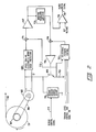
- FIG. 2 is shown a detailed block diagram of the circuitry of speed sense and torque generator circuit 58.
- the circuitry computes and compensates for the diameter of paper roll 13 using the principle that a DC motor generates an output voltage proportional to its rotational speed.
- the circuitry uses this generated voltage to vary the DC current applied to motor 55 to maintain a constant tension on paper web 32.
- spindle 57 and motor 55 are turning at a rate dependent on the diameter of the paper roll at each point in time.
- the ratio of motor speed to paper roll diameter is a parabolic function and is converted to a direct ratio in linearization amplifier 67.
- block 68 there are diodes (not shown) that are connected across the winding of motor 55 to prevent damage to the circuitry caused by turning motor 55 in reverse.
- diodes not shown
- block 68 there are also a bank of scaling resistors (not shown) that are jumper selectable, and are jumpered for different selected motor operating speeds.
- linearization circuit 67 is detecting an output voltage from motor 55 to determine the diameter of paper roll 13, any current through motor 55 reduces the detected voltage by the current times the internal winding resistance of the motor. All current caused by the voltage being detected, except for a few milliamps going through the scaling resistors in block 68, flows through transistor 69 and a current sensing resistor 70. The voltage drop across sensing resistor 70 is input to summing circuit 71 via lead 72. The voltage across sensing resistor 70 is summed with the scaled voltage output from the scaling resistors (not shown) in block 68 to provide a true level of the generated voltage from motor 55 as an input to linearization amplifier 67.
- the power required to be applied to motor 55 to produce a constant tension on paper web 32 is directly proportional to the radius of the remaining paper on paper roll 13, and thus inversely proportional to the linearized speed voltage.
- the output from linearization amplifier 67 is input to inverting translator amplifier which inverts the signal so that it is directly proportional to the linearized speed voltage signal.
- the inverted signal output from inverting amplifier 73 is summed in summing circuit 74 with a selectable feedback signal from selectable feedback control circuit 75 to produce a control signal which is input to current amplifier 76.
- the output from current amplifier 76 is connected to the base of power transistor 69 which is turned on and allows drive current flowing through motor 55 to flow through sensing resistor 70.
- the voltage across sensing resistor 70 is also input to selectable feedback control circuit 75, the output of which is input to summer circuit 74.
- Circuit 75 consists of several FET switches that control inputs from several tension level control logic control lines and also an on-off signal.
- the level control signals are used to program the amount of back tension to be applied to paper web 32 via power being applied to motor 55.
- the on-off signal is used to inhibit any power from being applied to motor 55.
- a negative power source is input to rewind current control circuit 76, which is basically a switch that is operated by a rewind control signal on lead 77, to apply reverse current to motor 55 that will cause a rewind torque to be generated by the motor.
- the rewind control signal is generated by a logic circuit (not shown) that controls the sequencing of the different DC torques motors as described previously in this specification.
- comparator 78 There is also a two input comparator 78 that has at one input the linearized speed signal output from amplifier 67, and the other input a reference voltage. When there has been a breakage of the paper web, or paper on paper roll 13 is depleted, spindle 57 stops and begins to turn counter-clockwise instead of clockwise. This is sensed by comparator 78 which provides an output signal on lead 79 indicating the breakage or running out of paper.
- FIG 3 is shown a combined detailed block diagram schematic of paper speed sense and motor torque circuit 59 and constant torque generator with load assist circuit 60, both shown in Figure 1.
- paper speed sense and motor torque generator 59 controls motor 33 in the first print mechanism 14
- constant torque generator with load assist circuit 60 controls motor 38 in the second print mechanism 15.
- the speed control of motor 33 is basically set by quartz crystal oscillator 80, the output of which is divided down by clock divider 81.
- One divided output from divider 81 is input to leading edge pulse generator 82 which also has the pulse output on lead 63 from incremental encoder 39 in Figure 1.
- the pulses output from encoder 39 are a feedback indicating the speed of motor 33.
- Generator 82 responds to the rising leading edge of each pulse output from incremental encoder 39 and to the clock signals from clock divider 81 to generate a narrow pulse for each pulse from encoder 39.
- the narrow pulses output from generator 82 are applied to, and each pulse triggers monostable circuit 83 which is a monostable multivibrator.
- the result is a series of precise pulses that are input to and integrated by counter 84 to produce a DC voltage.
- the DC output from integrator 84 is one of two inputs to a proportional integral differential amplifier 85.
- This lower frequency output is input to integrator 86 which integrates same and produces a DC reference voltage at its output.
- the DC reference voltage output from integrator 86 is also input to differential amplifier 85.
- Amplifier 85 is made up of two differential amplifiers, a first of which is a proportional stage having fast response, and the second of which is an integral stage having high gain but an integrated output for lower frequency response. This provides a more precise overall speed regulation.
- Differential amplifier 85 compares the two DC voltages at its two inputs and provides an output signal which is the difference between the two DC voltages.
- the output signal from differential amplifier 85 is a speed error signal for motor 33 and is input to pulse width modulator 87.
- the feedback speed error signal output of the integral differential amplifier is disabled until the printer is nearly at final speed. This is done by reducing its gain to unity.
- pulse width modulator 87 is enabled by the signal on lead 88 from logic circuit 20, its output is a pulse signal which has a pulse width that is proportional to the speed error signal.
- motor 33 is below its set speed the width of the pulses output from modulator 87 increase, and visa versa when the speed of motor 33 is greater than it should be.
- variable width pulses output from pulse width modulator 87 operate current drive amplifier 89 to gate pulses of current to motor 33.
- the width of current pulses applied to motor 33 is regulated, and when the two DC voltages input to differential amplifier 85 are equal, motor 33 is at its set speed.
- the control of motor 38 in second print mechanism 15 is basically done by a torque generator in which a DC voltage is converted to a constant current which produces a constant torque in motor 38, no matter what its speed.
- a precise reference voltage power supply has its output connected to a potentiometer 93 which is adjusted to provide an output voltage to set the desired torque of motor 38.
- the output voltage from potentiometer 93 is input to a summing circuit 94.
- a portion between five and fifty percent of the error signal output from modulator 85 is summed with the reference voltage from potentiometer 93 in summing circuit 94, and the sum is amplified by amplifier 96.
- the output of amplifier 96 is input to pulse width modulator 97.
- Modulator 97 operates the same as modulator 87 and provides output pulses having a pulse width proportional to the amplitude of the voltage at its input.
- Modulator 97 also is controlled by a turn on signal from logic circuit 20 in Figure 1 over lead 98.
- control circuit first enables back tension motor 55 via a turn on signal on lead 103 in Figure 1. Then power is applied to the drive motor in drive station 18. Thereafter, logic circuit provides a turn on signal on lead 98, Figure 3, to enable modulator 97 to gate amplifier 99 to provide power to motor 38. Finally, control logic circuit 20 provides a turn on signal on lead 88 to modulator 87 as previously described.
- pulse width modulator 97 When pulse width modulator 97 is enabled, it operates to gate pulses of current to motor 38. There is a current sensing resistor 100 connected in series with amplifier 99 and a feedback voltage across this resistor is applied to pulse width modulator 97 via lead 101.
- Constant torque generator circuit 61 in Figure 1 is alike the constant torque circuitry just described for motor 38 except that there is no feedback from the other motor control circuits, alike elements 94 and 95, on Figure 3. Accordingly, circuit 61 is not shown in any detail in any Figure and is not described any further. The turn on of circuit 61 is also controlled by control circuit via a signal on lead 102 for the sequence described two paragraphs back.
Landscapes
- Controlling Rewinding, Feeding, Winding, Or Abnormalities Of Webs (AREA)
- Handling Of Sheets (AREA)
- Handling Of Continuous Sheets Of Paper (AREA)
- Accessory Devices And Overall Control Thereof (AREA)
Applications Claiming Priority (2)
| Application Number | Priority Date | Filing Date | Title |
|---|---|---|---|
| US124695 | 1987-11-24 | ||
| US07/124,695 US4852785A (en) | 1987-11-24 | 1987-11-24 | Printer paper control apparatus and method |
Publications (2)
| Publication Number | Publication Date |
|---|---|
| EP0317762A2 true EP0317762A2 (fr) | 1989-05-31 |
| EP0317762A3 EP0317762A3 (fr) | 1990-03-07 |
Family
ID=22416313
Family Applications (1)
| Application Number | Title | Priority Date | Filing Date |
|---|---|---|---|
| EP88117397A Withdrawn EP0317762A3 (fr) | 1987-11-24 | 1988-10-19 | Méthode et dispositif pour la commande du papier d'une imprimante |
Country Status (4)
| Country | Link |
|---|---|
| US (1) | US4852785A (fr) |
| EP (1) | EP0317762A3 (fr) |
| JP (1) | JPH01267078A (fr) |
| AU (1) | AU616216B2 (fr) |
Cited By (14)
| Publication number | Priority date | Publication date | Assignee | Title |
|---|---|---|---|---|
| GB2236983A (en) * | 1989-10-17 | 1991-04-24 | Zirkon Druckmaschinen Gmbh | Regulation of web tension in a rotary printing machine |
| EP0673776A1 (fr) * | 1994-03-23 | 1995-09-27 | Kabushiki Kaisha TEC | Imprimante et méthode d'alimentation de papier continu à la zône d'impression |
| FR2724747A1 (fr) * | 1994-09-19 | 1996-03-22 | Kis | Installation automatique pour la realisation de documents personnalises sur leurs deux faces |
| EP0700788A3 (fr) * | 1994-08-26 | 1996-04-03 | Ko Pack Kk | |
| WO1996032290A3 (fr) * | 1995-04-12 | 1996-11-14 | Eastman Kodak Co | Impression numerique modulaire |
| US5704282A (en) * | 1996-09-17 | 1998-01-06 | Escher-Grad Technologies Inc. | Method of generating proofs of print signatures |
| EP0849077A1 (fr) * | 1996-12-20 | 1998-06-24 | Escher-Grad Technologies Inc. | Procédé de réalisation d'épreuves de cahiers |
| US5784077A (en) * | 1995-04-12 | 1998-07-21 | Eastman Kodak Company | Digital printing using plural cooperative modular printing devices |
| US5868069A (en) * | 1996-09-17 | 1999-02-09 | Escher-Grad Technologies Inc. | Method of generating proofs of print signatures |
| EP1190865A3 (fr) * | 2000-09-07 | 2002-04-10 | Seiko Epson Corporation | Appareil d'impression double face |
| US7303269B2 (en) | 2003-05-08 | 2007-12-04 | Seiko Epson Corporation | Recording apparatus and liquid ejecting apparatus |
| CN104023986A (zh) * | 2011-11-18 | 2014-09-03 | 柯达阿拉里斯股份有限公司 | 具有多个打印头的热敏打印机 |
| US10279605B2 (en) | 2007-06-29 | 2019-05-07 | R.R. Donnelley & Sons Company | Printing system |
| US10370214B2 (en) | 2017-05-31 | 2019-08-06 | Cryovac, Llc | Position control system and method |
Families Citing this family (25)
| Publication number | Priority date | Publication date | Assignee | Title |
|---|---|---|---|---|
| GB8830421D0 (en) * | 1988-12-30 | 1989-03-01 | Alcatel Business Systems | Postage stamp machine |
| US5129568A (en) * | 1990-01-22 | 1992-07-14 | Sequa Corporation | Off-line web finishing system |
| US5193456A (en) * | 1991-12-04 | 1993-03-16 | Crown Cork & Seal Company, Inc. | Apparatus for decorating beverage cans using a flexographic process |
| GB9206347D0 (en) * | 1992-03-24 | 1992-05-06 | Kodak Ltd | Film extraction unit |
| DE4241807A1 (de) * | 1992-12-11 | 1994-06-16 | Heidelberger Druckmasch Ag | Antrieb für eine Druckmaschine |
| US5365844A (en) * | 1993-07-29 | 1994-11-22 | Rockwell International Corporation | Device for controlling a web in a printing press |
| JPH07251995A (ja) * | 1994-03-16 | 1995-10-03 | Fujitsu Ltd | 媒体搬送制御装置 |
| TW417496U (en) * | 1995-07-14 | 2001-01-01 | Emhart Inc | Device for coupling golf club head to shaft and golf club assembly thereof |
| DE19623224C1 (de) * | 1996-06-11 | 1997-09-11 | Roland Man Druckmasch | Antrieb für eine Druckmaschine |
| US5735205A (en) * | 1996-11-07 | 1998-04-07 | Westvaco Corporation | Printing press controller |
| US5939646A (en) * | 1997-02-26 | 1999-08-17 | Hewlett-Packard Company | Sheet media weight detector |
| US5816152A (en) * | 1997-09-02 | 1998-10-06 | Delaware Capital Formation, Inc. | Reconfigurable printing press |
| GB9920012D0 (en) * | 1999-08-25 | 1999-10-27 | Xeikon Nv | Duplex printer and method of printing |
| DE10027442B4 (de) * | 2000-06-02 | 2005-12-01 | Man Roland Druckmaschinen Ag | Verfahren und Vorrichtung zur Detektion von Bahnrissen |
| US6735484B1 (en) * | 2000-09-20 | 2004-05-11 | Fargo Electronics, Inc. | Printer with a process diagnostics system for detecting events |
| US7163173B2 (en) * | 2000-12-22 | 2007-01-16 | Fuji Photo Film Co., Ltd. | Method of and apparatus for winding web |
| NL1027495C2 (nl) * | 2004-11-12 | 2006-05-15 | Oce Tech Bv | Printer en voorraadeenheid voor toepassing in deze printer. |
| US7530657B2 (en) * | 2005-02-03 | 2009-05-12 | Hewlett-Packard Development Company, L.P. | Media transport encoder accuracy |
| TWI331943B (en) * | 2007-12-03 | 2010-10-21 | Ind Tech Res Inst | Wire-receiving mechanism |
| FI122609B (fi) * | 2009-01-12 | 2012-04-13 | Abb Oy | Menetelmä, laitteisto ja tietokoneohjelmatuote aukirullaimen yhteydessä |
| TWI494261B (zh) | 2010-07-14 | 2015-08-01 | Bobst Sa | 用於轉換網狀基材,進料站及包裝生產機之保護轉換單元的方法 |
| DE102010060408A1 (de) | 2010-11-08 | 2012-05-10 | OCé PRINTING SYSTEMS GMBH | Anordnung zur Regelung des Bahnzugs einer Bedruckstoffbahn bei einem Druckgerät |
| DE102013014109A1 (de) * | 2012-09-13 | 2014-03-13 | Heidelberger Druckmaschinen Ag | Verfahren zum Einrichten und/oder Betreiben einer Rollendruckmaschine |
| US9616655B2 (en) * | 2013-12-19 | 2017-04-11 | Goss International Americas, Inc. | Method for reducing web printing press start-up waste, and related printing press and printed product |
| CN118929290B (zh) * | 2024-10-15 | 2024-12-10 | 四川创牌文化科技有限公司 | 一种用于酒瓶贴花纸印刷的进出料智能控制系统 |
Family Cites Families (11)
| Publication number | Priority date | Publication date | Assignee | Title |
|---|---|---|---|---|
| US1232217A (en) * | 1916-09-11 | 1917-07-03 | Ernest Camp | Means for coincidently playing pianos and organs. |
| US3257086A (en) * | 1963-08-02 | 1966-06-21 | John W Drenning | Tension equalizing control system |
| DE1761432C2 (de) * | 1968-05-18 | 1975-01-16 | Roland Offsetmaschinenfabrik Faber & Schleicher Ag, 6050 Offenbach | Vorrichtung zum Konstanthalten der Spannung einer durch eine Druckmaschine laufenden Werkstoffbahn |
| US3539085A (en) * | 1968-06-11 | 1970-11-10 | Web Press Eng Inc | Web control system |
| US3713600A (en) * | 1970-12-07 | 1973-01-30 | Harris Intertype Corp | Apparatus for use with a web fed mechanism |
| US4007866A (en) * | 1975-07-11 | 1977-02-15 | Moore Business Forms, Inc. | Web transport arrangement |
| DE3119398C2 (de) * | 1981-05-15 | 1984-05-30 | M.A.N.- Roland Druckmaschinen AG, 6050 Offenbach | Vorrichtung zur Einstellung der Länge einer zu bedruckenden Bahn in einer Rollenrotationsdruckmaschine |
| US4515053A (en) * | 1983-05-16 | 1985-05-07 | Dubois R Clark | Continuous web feeder with web cutting means |
| JPS6042048A (ja) * | 1983-08-18 | 1985-03-06 | Rengo Co Ltd | 多色印刷装置の位相合わせ装置 |
| US4696591A (en) * | 1986-02-19 | 1987-09-29 | Boyden Robert W | Fan folded printer output collector |
| DE3625387C1 (de) * | 1986-07-26 | 1987-11-26 | Triumph Adler Ag | Verfahren zum Betrieb von Schreibmaschinen,Druckern oder vergleichbaren Bueromaschinen |
-
1987
- 1987-11-24 US US07/124,695 patent/US4852785A/en not_active Expired - Lifetime
-
1988
- 1988-10-19 EP EP88117397A patent/EP0317762A3/fr not_active Withdrawn
- 1988-10-26 JP JP63270629A patent/JPH01267078A/ja active Pending
- 1988-10-27 AU AU24393/88A patent/AU616216B2/en not_active Ceased
Cited By (18)
| Publication number | Priority date | Publication date | Assignee | Title |
|---|---|---|---|---|
| GB2236983A (en) * | 1989-10-17 | 1991-04-24 | Zirkon Druckmaschinen Gmbh | Regulation of web tension in a rotary printing machine |
| EP0673776A1 (fr) * | 1994-03-23 | 1995-09-27 | Kabushiki Kaisha TEC | Imprimante et méthode d'alimentation de papier continu à la zône d'impression |
| US5505550A (en) * | 1994-03-23 | 1996-04-09 | Kabushiki Kaisha Tec | Printer and method of supplying continuous paper to printing portion |
| EP0700788A3 (fr) * | 1994-08-26 | 1996-04-03 | Ko Pack Kk | |
| FR2724747A1 (fr) * | 1994-09-19 | 1996-03-22 | Kis | Installation automatique pour la realisation de documents personnalises sur leurs deux faces |
| US5784077A (en) * | 1995-04-12 | 1998-07-21 | Eastman Kodak Company | Digital printing using plural cooperative modular printing devices |
| WO1996032290A3 (fr) * | 1995-04-12 | 1996-11-14 | Eastman Kodak Co | Impression numerique modulaire |
| US5704282A (en) * | 1996-09-17 | 1998-01-06 | Escher-Grad Technologies Inc. | Method of generating proofs of print signatures |
| US5868069A (en) * | 1996-09-17 | 1999-02-09 | Escher-Grad Technologies Inc. | Method of generating proofs of print signatures |
| EP0849077A1 (fr) * | 1996-12-20 | 1998-06-24 | Escher-Grad Technologies Inc. | Procédé de réalisation d'épreuves de cahiers |
| EP1190865A3 (fr) * | 2000-09-07 | 2002-04-10 | Seiko Epson Corporation | Appareil d'impression double face |
| US6916132B2 (en) | 2000-09-07 | 2005-07-12 | Seiko Epson Corporation | Double-sided printing apparatus |
| US7303269B2 (en) | 2003-05-08 | 2007-12-04 | Seiko Epson Corporation | Recording apparatus and liquid ejecting apparatus |
| US7334884B2 (en) | 2003-05-08 | 2008-02-26 | Seiko Epson Corporation | Recording apparatus and liquid ejecting apparatus |
| US10279605B2 (en) | 2007-06-29 | 2019-05-07 | R.R. Donnelley & Sons Company | Printing system |
| CN104023986A (zh) * | 2011-11-18 | 2014-09-03 | 柯达阿拉里斯股份有限公司 | 具有多个打印头的热敏打印机 |
| CN104023986B (zh) * | 2011-11-18 | 2016-08-31 | 柯达阿拉里斯股份有限公司 | 具有多个打印头的热敏打印机 |
| US10370214B2 (en) | 2017-05-31 | 2019-08-06 | Cryovac, Llc | Position control system and method |
Also Published As
| Publication number | Publication date |
|---|---|
| US4852785A (en) | 1989-08-01 |
| AU2439388A (en) | 1989-05-25 |
| JPH01267078A (ja) | 1989-10-24 |
| EP0317762A3 (fr) | 1990-03-07 |
| AU616216B2 (en) | 1991-10-24 |
Similar Documents
| Publication | Publication Date | Title |
|---|---|---|
| US4852785A (en) | Printer paper control apparatus and method | |
| US6626343B2 (en) | Method and apparatus for pinless feeding of web to a utilization device | |
| US5818470A (en) | System and method for directly feeding paper to printing devices | |
| US5979732A (en) | Method and apparatus for pinless feeding of web to a utilization device | |
| EP0863445B1 (fr) | Procédé pour déterminer le pois des feuilles | |
| US5774777A (en) | Continuous recording medium friction-conveying mechanism in image forming apparatus | |
| US6000595A (en) | Method and apparatus for pinless feeding of web to a utilization device | |
| EP1063191A1 (fr) | Dispositif de contrôle du repère d'une bande | |
| US5947408A (en) | Recording device using continuous paper and method of feeding continuous paper | |
| US6799507B2 (en) | Web printers | |
| US5809390A (en) | Device for controlling pinless paper movement in a continuous forms printer | |
| US6089566A (en) | Sheet supply and transfer device for printers presumable of sheet size for pinch rollers | |
| EP2042935B1 (fr) | Appareil de formation d'images | |
| US4796066A (en) | Printer apparatus having two-sided printing capability | |
| US4903956A (en) | Sheet stacking apparatus having positive control system for trailing sheet ends | |
| US5226742A (en) | Electrically powered paper stacking apparatus and method for impact printers and the like | |
| US6507768B1 (en) | Method and system to compensate for wear in a sheet handling device | |
| US6532356B2 (en) | Guide mechanism, paper feed control method, and image-forming device | |
| JP2964868B2 (ja) | 熱転写カードプリンタ | |
| JPH09295722A (ja) | 媒体搬送制御装置 | |
| JPH11165906A (ja) | 用紙搬送装置 | |
| JPH04255374A (ja) | 印字装置の用紙送り制御方法及び機構 | |
| JPS62105862A (ja) | 排紙装置 | |
| JPH06135607A (ja) | プリンタの用紙駆動装置 | |
| JPH10109802A (ja) | ロールシート給送装置及びシート処理装置 |
Legal Events
| Date | Code | Title | Description |
|---|---|---|---|
| PUAI | Public reference made under article 153(3) epc to a published international application that has entered the european phase |
Free format text: ORIGINAL CODE: 0009012 |
|
| AK | Designated contracting states |
Kind code of ref document: A2 Designated state(s): DE FR GB IT |
|
| PUAL | Search report despatched |
Free format text: ORIGINAL CODE: 0009013 |
|
| AK | Designated contracting states |
Kind code of ref document: A3 Designated state(s): DE FR GB IT |
|
| 17P | Request for examination filed |
Effective date: 19900808 |
|
| 17Q | First examination report despatched |
Effective date: 19920203 |
|
| STAA | Information on the status of an ep patent application or granted ep patent |
Free format text: STATUS: THE APPLICATION HAS BEEN WITHDRAWN |
|
| 18W | Application withdrawn |
Withdrawal date: 19920605 |