EP0317831A2 - Haltegitter für Kernbrennstäbe - Google Patents
Haltegitter für Kernbrennstäbe Download PDFInfo
- Publication number
- EP0317831A2 EP0317831A2 EP88118690A EP88118690A EP0317831A2 EP 0317831 A2 EP0317831 A2 EP 0317831A2 EP 88118690 A EP88118690 A EP 88118690A EP 88118690 A EP88118690 A EP 88118690A EP 0317831 A2 EP0317831 A2 EP 0317831A2
- Authority
- EP
- European Patent Office
- Prior art keywords
- fuel
- rod
- nuclear
- dimple
- strap section
- Prior art date
- Legal status (The legal status is an assumption and is not a legal conclusion. Google has not performed a legal analysis and makes no representation as to the accuracy of the status listed.)
- Granted
Links
Images


Classifications
-
- G—PHYSICS
- G21—NUCLEAR PHYSICS; NUCLEAR ENGINEERING
- G21C—NUCLEAR REACTORS
- G21C3/00—Reactor fuel elements and their assemblies; Selection of substances for use as reactor fuel elements
- G21C3/30—Assemblies of a number of fuel elements in the form of a rigid unit
- G21C3/32—Bundles of parallel pin-, rod-, or tube-shaped fuel elements
- G21C3/34—Spacer grids
- G21C3/356—Spacer grids being provided with fuel element supporting members
- G21C3/3563—Supporting members formed only by deformations in the strips
-
- Y—GENERAL TAGGING OF NEW TECHNOLOGICAL DEVELOPMENTS; GENERAL TAGGING OF CROSS-SECTIONAL TECHNOLOGIES SPANNING OVER SEVERAL SECTIONS OF THE IPC; TECHNICAL SUBJECTS COVERED BY FORMER USPC CROSS-REFERENCE ART COLLECTIONS [XRACs] AND DIGESTS
- Y02—TECHNOLOGIES OR APPLICATIONS FOR MITIGATION OR ADAPTATION AGAINST CLIMATE CHANGE
- Y02E—REDUCTION OF GREENHOUSE GAS [GHG] EMISSIONS, RELATED TO ENERGY GENERATION, TRANSMISSION OR DISTRIBUTION
- Y02E30/00—Energy generation of nuclear origin
- Y02E30/30—Nuclear fission reactors
Definitions
- the present invention relates generally to nuclear fuel assemblies and, more particularly, to a nuclear fuel rod supporting grid therefor.
- the reactor core consists of a large number of elongate fuel assemblies each including a plurality of fuel rods held in an organized array by means of support grids spaced apart axially along the fuel assembly and attached to elongate structural elements, usually control-rod guide thimbles, which have end structures of the fuel assembly secured to opposite ends thereof.
- the fuel rods extending through the various cells are laterally supported therein by means of detents, such as compliant springs and relatively rigid dimples, which are formed out of the metal of the interleaved straps and project into the respective cells far enough to frictionally engage and laterally support the fuel rods extending therethrough.
- detents such as compliant springs and relatively rigid dimples, which are formed out of the metal of the interleaved straps and project into the respective cells far enough to frictionally engage and laterally support the fuel rods extending therethrough.
- the springs in the cells of such conventional grid are oriented substantially parallel to the longitudinal axes of the respective cells whereas the dimples, which are arcuate so as to define open spaces between themselves and the respective strap sections from which they protrude, are oriented in planes substantially perpendicular to the longitudinal axes of the cells so as to minimize the flow impedance offered to reactor coolant flowing through the grid.
- the invention has for its principal object to provide an improved grid with dimples which likewise minimize flow impedance and, in addition, are essentially immune from damage caused during insertion of fuel rods into the grid cells.
- the invention accordingly resides in a nuclear-fuel-rod supporting grid composed of a plurality of straps interleaved with one another so as to form a matrix of fuel-rod receiving cells each defined by sections of said straps forming walls of the respective cell and having fuel-rod engaging and supporting structure formed thereon, the fuel-rod engaging and supporting structure on each strap section including at least one elongate, arcuate dimple which has opposite ends thereof connected to the associated strap section and which arches from the latter into the associated cell in a manner such as to define, between itself and the plane of said associated strap section, a space permitting unimpeded flow of coolant therethrough, characterized in that said dimple is slanted, with respect to the longitudinal axis of the associated cell, in a direction substantially parallel to the strap section from which the dimple protrudes.
- Each arcuate dimple thus slanted forms in effect a ramp over which a fuel-rod gripper employed during insertion of a fuel rod, and the fuel rod being inserted, can slide without the risk of snagging such as could cause cocking of the dimple and, consequentially, result in scratching and fretting of the fuel rod being inserted.
- each dimple is slanted about forty-five degrees relative to the longitudinal axis of the associated cell
- the fuel-rod engaging and supporting structure on each strap section preferably includes two such slanted dimples and also a slanted grid spring, as defined in subordinate claims appended hereto.
- the fuel assembly shown therein and designated generally with reference numeral 10 is of the type commonly used in pressurized-water reactors. Basically, it comprises a lower end structure or bottom nozzle 12 for supporting the assembly on the lower core plate (not shown) in the core region of a nuclear reactor (not shown), a plurality of guide tubes or thimbles 14 longitudinally extending upward from the bottom nozzle 12, a plurality of transverse grids 16 axially spaced apart along, and supported by, the guide thimbles 14, a plurality of elongate fuel rods 18 transversely spaced and supported in an organized array by the grids 16, an instrumentation tube 20 located in the center of the fuel assembly, and an upper end structure or top nozzle 22 attached to the upper ends of the guide thimbles 14. With the parts thus arranged, the fuel assembly 10 forms an integral unit which can be conveniently handled without damage to its parts.
- Each fuel rod 18 contains pellets 24 of fissile fuel and has its opposite ends hermetically sealed by means of end plugs 26 and 28, a plenum spring 30 being disposed between the upper end plug 26 and the stack of pellets 24 to maintain the latter firmly stacked within the rod 18.
- the top nozzle 22 supports a rod cluster control mechanism 34 including an internally threaded cylindrical member 36 with radially extending arms 38 each of which is connected to a control rod 32 axially movable in one of the guide thimbles 14, the control mechanism 34 being operable to move the control rods 32 up and down so as to control the fission process in the fuel assembly 10, all as well known in the art.
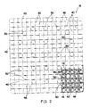
- the grid 16 illustrated therein is composed of inner straps 40 and outer straps 42 each having slots 44 formed therein to enable the straps to be interleaved with one another in an egg-crate-like configuration so as to form a matrix of open cells 46 for the fuel rods 18, and openings 48 for the guide thimbles, to extend therethrough.
- the straps 40, 42 are secured, preferably welded, together at their intersections.
- the openings 48 have inserted therein sleeves 50 which are attached, preferably welded, to the inner straps 40 and are employed to affix the grid 16 to the guide thimbles 14.
- Reference numeral 80 designates mixing vanes 80 formed, if desired, along the downstream (having regard to coolant flow) edges of the respective inner and outer straps of the grid 16.
- Each of the fuel-rod receiving cells 46 is defined by two pairs of oppositely disposed walls formed by strap sections which have fuel-rod engaging and supporting structure formed thereon. More particularly, and as shown in Figs. 3 to 5, the outer straps 42 define cell-wall sections 54 each of which has thereon a pair of vertically spaced fuel-rod engaging dimples 56 formed integral therewith. Similarly, the inner straps 40 define cell-wall sections 52 each of which has disposed thereon two vertically spaced dimples 78 and a resiliently yieldable spring 60 therebetween, the dimples 78 projecting from one side of the associated strap section 52, and the spring 60 projecting from the opposite side thereof.
- Each cell 46 formed along the periphery of the grid 16 by the inner and outer straps 40, 42 has associated therewith four dimples 56,78 and two springs 60, and each cell 46 formed in the grid 16 only by inner straps 40 has associated therewith four dimples 78 and two springs 60; thus, the fuel rod in each cell 46 is contacted and supported at six circumferentially and axially displaced locations thereon.
- each spring 60 consist of flexible, resiliently yieldable material, e.g. stainless steel, which is formed, preferably stamped, out of the respective inner straps 40.
- each spring 60 comprises two elongate spring legs 62 which extend in substantially parallel spaced relationship with respect to one another in a direction substantially parallel to the longitudinal axis of the associated grid cell 46, and an elongate spring cross-member 64 which extends diagonally between the two spring legs 62 and has its opposite ends integrally connected thereto.
- Each spring 60 thus formed by two spring legs 62 and a diagonal cross-member 64 has an effective length substantially greater than the actual length which it occupies on the associated strap section 52.
- each spring 60 preferably is slanted at an angle of about 45° with respect to the associated spring legs 62 and to the longitudinal axis of the associated grid cell 46.
- Each spring leg 62 is slightly bowed out of the plane of the associated strap section 52 and projects from the latter into the associated grid cell 46.
- each cross-member 64 is arched along a longitudinal section thereof and projects from its associated wall section 52 toward the longitudinal axis of the associated grid cell 46, however to a greater extent than the spring legs 62, i.e. far enough for its apex to engage and support the fuel rod 18 extending through the associated cell 46.
- the cross-member 64 of the spring 60 Upon insertion of a fuel rod into the cell 46, the cross-member 64 of the spring 60 will resiliently yield and be deflected by the fuel rod toward the associated strap section 52. In consequence of this resilient deflection of the cross-member 64, the spring legs 62 of the spring 60 will likewise be resiliently deflected, back into the plane of the associated strap section 52, and hence will not impede the flow of coolant through the grid cell 46.
- the dimples 78 are formed integral with the inner straps 40, preferably being stamped from the respective strap sections 52, and each strap section 52 has disposed thereon two dimples 78 and one grid spring 60 therebetween, the dimples 78 projecting from one side of the strap section and the grid spring 60 projecting from its opposite side.
- Each dimple 78 is arcuate, along a longitudinal section therethrough, and arches from the plane of the associated strap section 52 inwards of the respective grid cell 46 adjacent thereto.
- each dimple 78 is diagonal or slanted, preferably about 45°, with respect to the longitudinal axis of the associated grid cells 46, in a direction substantially parallel to the strap section 52 from which it protrudes.
- the two slanted dimples 78 on each wall section 52 are oriented substantially parallel with respect to each other and substantially orthogonal, or perpendicular, with respect to the longitudinal orientation of the diagonal cross-member 64 of the associated spring 60.
- Figs. 6-8 and Figs. 9-11 the two slanted dimples 78 on each wall section 52 are oriented substantially parallel with respect to each other and substantially orthogonal, or perpendicular, with respect to the longitudinal orientation of the diagonal cross-member 64 of the associated spring 60.
- the two slanted dimples 78 on each wall section 52 extend in directions substantially perpendicular to one another, one dimple 78 being oriented substantially parallel and the other substantially perpendicular with respect to the diagonal cross- member 64 of the associated spring 60.
- the slanted dimples 78 and the diagonal cross-member 64 of the associate spring 60 all are oriented substantially in parallel with respect to each other.
- each arcuate dimple 78 is slanted, with respect to the longitudinal axes of the associated grid cell 46, in a direction substantially parallel to the wall section 52 from which it protrudes, thus affording the advantages initially mentioned herein.
Landscapes
- Physics & Mathematics (AREA)
- Engineering & Computer Science (AREA)
- Plasma & Fusion (AREA)
- General Engineering & Computer Science (AREA)
- High Energy & Nuclear Physics (AREA)
- Fuel Cell (AREA)
Applications Claiming Priority (2)
| Application Number | Priority Date | Filing Date | Title |
|---|---|---|---|
| US07/125,514 US4803043A (en) | 1987-05-22 | 1987-11-25 | Nuclear fuel rod grid spring and dimple structures |
| US125514 | 1987-11-25 |
Publications (3)
| Publication Number | Publication Date |
|---|---|
| EP0317831A2 true EP0317831A2 (de) | 1989-05-31 |
| EP0317831A3 EP0317831A3 (en) | 1990-01-10 |
| EP0317831B1 EP0317831B1 (de) | 1993-03-17 |
Family
ID=22420065
Family Applications (1)
| Application Number | Title | Priority Date | Filing Date |
|---|---|---|---|
| EP88118690A Expired - Lifetime EP0317831B1 (de) | 1987-11-25 | 1988-11-10 | Haltegitter für Kernbrennstäbe |
Country Status (6)
| Country | Link |
|---|---|
| US (1) | US4803043A (de) |
| EP (1) | EP0317831B1 (de) |
| JP (2) | JPH01167696A (de) |
| KR (1) | KR0121455B1 (de) |
| DE (1) | DE3879396D1 (de) |
| ES (1) | ES2040815T3 (de) |
Cited By (1)
| Publication number | Priority date | Publication date | Assignee | Title |
|---|---|---|---|---|
| US5331678A (en) * | 1993-04-27 | 1994-07-19 | Combustion Engineering, Inc. | Spacer grid rod support system |
Families Citing this family (27)
| Publication number | Priority date | Publication date | Assignee | Title |
|---|---|---|---|---|
| JPH01173898A (ja) * | 1987-09-10 | 1989-07-10 | Mitsubishi Nuclear Fuel Co Ltd | 原子炉燃料集合体の支持格子 |
| US4895698A (en) * | 1988-03-14 | 1990-01-23 | Westinghouse Electric Corp. | Nuclear fuel rod grip with modified diagonal spring structures |
| US4923669A (en) * | 1989-02-21 | 1990-05-08 | Westinghouse Electric Corp. | Nuclear fuel rod grid spring and dimple structures having chamfered edges for reduced pressure drop |
| US5139736A (en) * | 1991-04-03 | 1992-08-18 | Combustion Engineering, Inc. | Fuel assembly support grid |
| US5444748A (en) * | 1994-04-04 | 1995-08-22 | Westinghouse Electric Corporation | Grid structure for supporting fuel rods in a nuclear reactor |
| US5488644A (en) | 1994-07-13 | 1996-01-30 | General Electric Company | Spring assemblies for adjoining nuclear fuel rod containing ferrules and a spacer formed of the spring assemblies and ferrules |
| US5519747A (en) | 1994-10-04 | 1996-05-21 | General Electric Company | Apparatus and methods for fabricating spacers for a nuclear fuel rod bundle |
| US5546437A (en) | 1995-01-11 | 1996-08-13 | General Electric Company | Spacer for nuclear fuel rods |
| US5566217A (en) | 1995-01-30 | 1996-10-15 | General Electric Company | Reduced height spacer for nuclear fuel rods |
| US5675621A (en) | 1995-08-17 | 1997-10-07 | General Electric Company | Reduced height flat spring spacer for nuclear fuel rods |
| US6144716A (en) * | 1997-07-02 | 2000-11-07 | Westinghouse Electric Corp. | Nuclear fuel assembly grid with diagonal fuel retaining springs |
| ES2216356T3 (es) * | 1998-01-27 | 2004-10-16 | Framatome Anp Gmbh | Espaciador de un elemento combustible de una central nuclear. |
| KR100287278B1 (ko) * | 1998-02-04 | 2001-04-16 | 장인순 | 회전유동발생장치를가진핵연료집합체지지격자 |
| JP3872598B2 (ja) * | 1998-07-08 | 2007-01-24 | 三菱重工業株式会社 | 原子炉燃料集合体の支持格子 |
| KR100330355B1 (ko) | 1999-06-04 | 2002-04-01 | 장인순 | 회전유동발생 날개를 가진 덕트형 핵연료 집합체 지지격자 |
| KR100330354B1 (ko) | 1999-06-11 | 2002-04-01 | 장인순 | 핵연료집합체의 바가지형 혼합날개 지지격자체 |
| US6310932B1 (en) * | 2000-10-23 | 2001-10-30 | Westinghouse Electric Company Llc | Fretting resistant spring design |
| KR100444699B1 (ko) * | 2001-12-26 | 2004-08-21 | 한국수력원자력 주식회사 | 입술형 다목적 핵연료 지지격자체 |
| US6606369B1 (en) * | 2002-03-06 | 2003-08-12 | Westinghouse Electric Company Llc | Nuclear reactor with improved grid |
| FR2837975B1 (fr) * | 2002-03-29 | 2005-08-26 | Framatome Anp | Grille entretoise d'un assemblage de combustible pour un reacteur nucleaire refroidi par de l'eau legere |
| US6819733B2 (en) | 2002-05-15 | 2004-11-16 | Westinghouse Electric Company Llc | Fuel assembly and associated grid for nuclear reactor |
| FR2878645B1 (fr) * | 2004-11-30 | 2007-02-09 | Framatome Anp Sas | Grille de maintien de crayons pour assemblage de combustible nucleaire et assemblage corresondant |
| FR2910687B1 (fr) * | 2006-12-26 | 2016-08-26 | Areva Np | Grille-entretoise a elements d'appui en forme de selle de cheval et assemblage de combustible nucleaire correspondant. |
| US8062055B2 (en) * | 2009-06-11 | 2011-11-22 | Tyco Electronics Corporation | Multi-position connector |
| US9378852B2 (en) | 2012-04-17 | 2016-06-28 | Bwxt Mpower, Inc. | Spacer grids for nuclear reactor |
| CN102760498B (zh) * | 2012-07-18 | 2015-04-22 | 中国核动力研究设计院 | 用于核燃料组件具有降低勾挂风险的定位格架 |
| US9734923B2 (en) * | 2013-06-20 | 2017-08-15 | Westinghouse Electric Company Llc | Nuclear fuel assembly having a spacer grid with one or more seamless corners |
Family Cites Families (5)
| Publication number | Priority date | Publication date | Assignee | Title |
|---|---|---|---|---|
| US3928131A (en) * | 1969-08-14 | 1975-12-23 | William J Wachter | Grid structure for nuclear reactor fuel assembly |
| US3933584A (en) * | 1973-04-23 | 1976-01-20 | Nuclear Fuel Services, Inc. | Grid for nuclear fuel assembly |
| DE2642220A1 (de) * | 1976-09-20 | 1978-03-23 | Kraftwerk Union Ag | Abstandshalter fuer kernreaktorbrennelemente |
| FR2465297A1 (fr) * | 1979-09-07 | 1981-03-20 | Commissariat Energie Atomique | Grille d'espacement pour elements combustibles de reacteurs nucleaires |
| US4692302A (en) * | 1983-12-30 | 1987-09-08 | Westinghouse Electric Corp. | Coolant flow mixer grid for a nuclear reactor fuel assembly |
-
1987
- 1987-11-25 US US07/125,514 patent/US4803043A/en not_active Expired - Lifetime
-
1988
- 1988-11-10 ES ES198888118690T patent/ES2040815T3/es not_active Expired - Lifetime
- 1988-11-10 DE DE8888118690T patent/DE3879396D1/de not_active Expired - Lifetime
- 1988-11-10 EP EP88118690A patent/EP0317831B1/de not_active Expired - Lifetime
- 1988-11-25 KR KR1019880015568A patent/KR0121455B1/ko not_active Expired - Fee Related
- 1988-11-25 JP JP63296390A patent/JPH01167696A/ja active Pending
-
1997
- 1997-07-01 JP JP005677U patent/JPH1012U/ja active Pending
Cited By (2)
| Publication number | Priority date | Publication date | Assignee | Title |
|---|---|---|---|---|
| US5331678A (en) * | 1993-04-27 | 1994-07-19 | Combustion Engineering, Inc. | Spacer grid rod support system |
| WO1994025965A1 (en) * | 1993-04-27 | 1994-11-10 | Combustion Engineering, Inc. | Spacer grid rod support system |
Also Published As
| Publication number | Publication date |
|---|---|
| ES2040815T3 (es) | 1993-11-01 |
| DE3879396D1 (de) | 1993-04-22 |
| EP0317831A3 (en) | 1990-01-10 |
| KR0121455B1 (ko) | 1997-11-20 |
| JPH1012U (ja) | 1998-01-16 |
| JPH01167696A (ja) | 1989-07-03 |
| EP0317831B1 (de) | 1993-03-17 |
| KR890008854A (ko) | 1989-07-12 |
| US4803043A (en) | 1989-02-07 |
Similar Documents
| Publication | Publication Date | Title |
|---|---|---|
| EP0317831B1 (de) | Haltegitter für Kernbrennstäbe | |
| EP0332941B1 (de) | Kernbrennstoffbündelstützgitter | |
| US4885127A (en) | Nuclear fuel rod support grid with attachable spring and dimple support spacers | |
| EP0196598B1 (de) | Abstandsgitter eines Kernreaktorbrennelementes | |
| US4585616A (en) | Nuclear fuel spacer grid with improved outer straps | |
| US4726926A (en) | Mixing grid | |
| US4474730A (en) | Nuclear fuel spacer grid | |
| US4923669A (en) | Nuclear fuel rod grid spring and dimple structures having chamfered edges for reduced pressure drop | |
| EP0452706B1 (de) | Abstandshalter und Feder für Kernbrennstabbündel | |
| US5002726A (en) | Nuclear fuel assembly spacer and loop spring with enhanced flexibility | |
| US4125435A (en) | Grid lattice with sliding strap | |
| US4585615A (en) | Nuclear fuel spacer grid with improved grid straps | |
| US3664924A (en) | Nuclear reactor spring ferrule spacer grid | |
| US4389369A (en) | Bi-metallic grid for a nuclear reactor fuel assembly | |
| US4297170A (en) | Devices for transversely holding the fuel rods of a nuclear reactor assembly | |
| US5085827A (en) | Nuclear fuel assembly spacer and loop spring with enhanced flexibility | |
| EP0200046A1 (de) | Kernbrennstabhaltegitter mit Vielfachnoppenanordnung | |
| US4028180A (en) | Support grid for fuel elements in a nuclear reactor | |
| EP0291736B1 (de) | Kernbrennstoffstabstützgitter | |
| EP0378094B1 (de) | Zwischenmischgitter | |
| US4725402A (en) | Welded nuclear fuel grid and method | |
| JPH067187B2 (ja) | スペーサグリッドと一体の旋回羽根 | |
| GB2060981A (en) | Spacer grid | |
| Finch | Support grid for fuel elements in a nuclear reactor | |
| JPH01299494A (ja) | 燃料棒スペーサ |
Legal Events
| Date | Code | Title | Description |
|---|---|---|---|
| PUAI | Public reference made under article 153(3) epc to a published international application that has entered the european phase |
Free format text: ORIGINAL CODE: 0009012 |
|
| AK | Designated contracting states |
Kind code of ref document: A2 Designated state(s): BE DE ES FR GB IT SE |
|
| PUAL | Search report despatched |
Free format text: ORIGINAL CODE: 0009013 |
|
| AK | Designated contracting states |
Kind code of ref document: A3 Designated state(s): BE DE ES FR GB IT SE |
|
| 17P | Request for examination filed |
Effective date: 19900216 |
|
| 17Q | First examination report despatched |
Effective date: 19911024 |
|
| GRAA | (expected) grant |
Free format text: ORIGINAL CODE: 0009210 |
|
| AK | Designated contracting states |
Kind code of ref document: B1 Designated state(s): BE DE ES FR GB IT SE |
|
| PG25 | Lapsed in a contracting state [announced via postgrant information from national office to epo] |
Ref country code: IT Free format text: LAPSE BECAUSE OF FAILURE TO SUBMIT A TRANSLATION OF THE DESCRIPTION OR TO PAY THE FEE WITHIN THE PRE;WARNING: LAPSES OF ITALIAN PATENTS WITH EFFECTIVE DATE BEFORE 2007 MAY HAVE OCCURRED AT ANY TIME BEFORE 2007. THE CORRECT EFFECTIVE DATE MAY BE DIFFERENT FROM THE ONE RECORDED.SCRIBED TIME-LIMIT Effective date: 19930317 Ref country code: DE Effective date: 19930317 |
|
| REF | Corresponds to: |
Ref document number: 3879396 Country of ref document: DE Date of ref document: 19930422 |
|
| ET | Fr: translation filed | ||
| REG | Reference to a national code |
Ref country code: ES Ref legal event code: FG2A Ref document number: 2040815 Country of ref document: ES Kind code of ref document: T3 |
|
| PLBE | No opposition filed within time limit |
Free format text: ORIGINAL CODE: 0009261 |
|
| STAA | Information on the status of an ep patent application or granted ep patent |
Free format text: STATUS: NO OPPOSITION FILED WITHIN TIME LIMIT |
|
| 26N | No opposition filed | ||
| EAL | Se: european patent in force in sweden |
Ref document number: 88118690.2 |
|
| PGFP | Annual fee paid to national office [announced via postgrant information from national office to epo] |
Ref country code: SE Payment date: 20011106 Year of fee payment: 14 |
|
| REG | Reference to a national code |
Ref country code: GB Ref legal event code: IF02 |
|
| PG25 | Lapsed in a contracting state [announced via postgrant information from national office to epo] |
Ref country code: SE Free format text: LAPSE BECAUSE OF NON-PAYMENT OF DUE FEES Effective date: 20021111 |
|
| EUG | Se: european patent has lapsed | ||
| PGFP | Annual fee paid to national office [announced via postgrant information from national office to epo] |
Ref country code: GB Payment date: 20041004 Year of fee payment: 17 |
|
| PG25 | Lapsed in a contracting state [announced via postgrant information from national office to epo] |
Ref country code: GB Free format text: LAPSE BECAUSE OF NON-PAYMENT OF DUE FEES Effective date: 20051110 |
|
| GBPC | Gb: european patent ceased through non-payment of renewal fee |
Effective date: 20051110 |
|
| PGFP | Annual fee paid to national office [announced via postgrant information from national office to epo] |
Ref country code: ES Payment date: 20071114 Year of fee payment: 20 |
|
| PGFP | Annual fee paid to national office [announced via postgrant information from national office to epo] |
Ref country code: BE Payment date: 20071212 Year of fee payment: 20 |
|
| PGFP | Annual fee paid to national office [announced via postgrant information from national office to epo] |
Ref country code: FR Payment date: 20071105 Year of fee payment: 20 |
|
| BE20 | Be: patent expired |
Owner name: *WESTINHOUSE ELECTRIC CY LLC Effective date: 20081110 |
|
| REG | Reference to a national code |
Ref country code: ES Ref legal event code: FD2A Effective date: 20081111 |
|
| PG25 | Lapsed in a contracting state [announced via postgrant information from national office to epo] |
Ref country code: ES Free format text: LAPSE BECAUSE OF EXPIRATION OF PROTECTION Effective date: 20081111 |