US4803043A - Nuclear fuel rod grid spring and dimple structures - Google Patents
Nuclear fuel rod grid spring and dimple structures Download PDFInfo
- Publication number
- US4803043A US4803043A US07/125,514 US12551487A US4803043A US 4803043 A US4803043 A US 4803043A US 12551487 A US12551487 A US 12551487A US 4803043 A US4803043 A US 4803043A
- Authority
- US
- United States
- Prior art keywords
- cell
- wall section
- longitudinal axis
- fuel rod
- recited
- Prior art date
- Legal status (The legal status is an assumption and is not a legal conclusion. Google has not performed a legal analysis and makes no representation as to the accuracy of the status listed.)
- Expired - Lifetime
Links
Images




Classifications
-
- G—PHYSICS
- G21—NUCLEAR PHYSICS; NUCLEAR ENGINEERING
- G21C—NUCLEAR REACTORS
- G21C3/00—Reactor fuel elements and their assemblies; Selection of substances for use as reactor fuel elements
- G21C3/30—Assemblies of a number of fuel elements in the form of a rigid unit
- G21C3/32—Bundles of parallel pin-, rod-, or tube-shaped fuel elements
- G21C3/34—Spacer grids
-
- G—PHYSICS
- G21—NUCLEAR PHYSICS; NUCLEAR ENGINEERING
- G21C—NUCLEAR REACTORS
- G21C3/00—Reactor fuel elements and their assemblies; Selection of substances for use as reactor fuel elements
- G21C3/30—Assemblies of a number of fuel elements in the form of a rigid unit
- G21C3/32—Bundles of parallel pin-, rod-, or tube-shaped fuel elements
- G21C3/34—Spacer grids
- G21C3/356—Spacer grids being provided with fuel element supporting members
- G21C3/3563—Supporting members formed only by deformations in the strips
-
- Y—GENERAL TAGGING OF NEW TECHNOLOGICAL DEVELOPMENTS; GENERAL TAGGING OF CROSS-SECTIONAL TECHNOLOGIES SPANNING OVER SEVERAL SECTIONS OF THE IPC; TECHNICAL SUBJECTS COVERED BY FORMER USPC CROSS-REFERENCE ART COLLECTIONS [XRACs] AND DIGESTS
- Y02—TECHNOLOGIES OR APPLICATIONS FOR MITIGATION OR ADAPTATION AGAINST CLIMATE CHANGE
- Y02E—REDUCTION OF GREENHOUSE GAS [GHG] EMISSIONS, RELATED TO ENERGY GENERATION, TRANSMISSION OR DISTRIBUTION
- Y02E30/00—Energy generation of nuclear origin
- Y02E30/30—Nuclear fission reactors
Definitions
- the present invention relates generally to nuclear fuel assemblies and, more particularly, is concerned with a nuclear fuel rod grid having unique fuel rod engaging spring and dimple structures.
- the reactor core is comprised of a large number of elongated fuel assemblies.
- Conventional designs of these fuel assemblies include a plurality of fuel rods held in an organized array by a plurality of grids spaced axially along the fuel assembly length and attached to a plurality of elongated control guide thimbles of the fuel assembly. Top and bottom nozzles on opposite ends of the fuel assembly are secured to the guide thimbles which extend slightly above and below the ends of the fuel rods.
- the grids as well known in the art are used to precisely maintain the spacing between the fuel rods in the reactor core, prevent rod vibration, provide lateral support for the fuel rods, and, to some extent, frictionally retain the rods against longitudinal movement.
- Representative grid designs include those of some of the patent applications cross-referenced above.
- One popular conventional grid design including a multiplicity of interleaved inner and outer straps having an egg-crate configuration foming a multiplicity of cells which individually accept the fuel rods and control rod guide thimbles.
- the cells of each grid which accept and support the fuel rods at a given axial location therealong typically use relatively resilient springs and/or relatively rigid protrusions (called dimples) formed into the metal of the interleaved straps.
- the springs and dimples of each grid cell frictionally engage or contact the respective fuel rod extending through the cell.
- the outer straps are attached together and peripherally enclose the inner straps to impart strength and rigidity to the grid.
- the present invention provides a fuel rod grid designed to satisfy the aforementioned needs.
- the grid of the present invention includes inner grid straps containing unique fuel rod engaging spring structures and dimples on wall sections thereof defining a matrix of I0 fuel rod receiving grid cells.
- Each spring structure is composed of a pair of laterally spaced spring leg members each extending vertically and anchored at their respective pairs of opposite ends and a cross spring member which extends diagonally between and integrally connects to the spring leg members. Both of the leg members are curved slightly and the cross is arched, all projecting toward the longitudinal axis of the grid cell.
- the spring structure has an effective length approximately two times greater than the actual length it occupies within the grid, allowing a substantial reduction in the height of the grid over the one having the prior vertically-oriented spring configuration.
- the cross spring member is preferably set approximately forty-five degrees to the direction of the longitudinal axis of the grid cell and to the direction of coolant fluid flow through the grid and fuel assembly in which the grid is used. Yet the cross spring member is open with respect to the direction of flow. Forty-five degrees appears to be the optimum angle so that grid height can be reduced and spring profile exposed to coolant flow can be minimized. Angles greater than fortyfive degrees will increase pressure drop due to increased grid height, whereas lesser angles increase blockage of flow. The profile of the improved spring structure as seen by the flow is actually less than a horizontal dimple because smaller radii can be stamped due to the forty-five degree angle.
- the diagonal cross member also stiffens the inner grid strap and thereby the grid and increases its stability.
- the design of the unique spring structure gives a soft compliant spring action.
- a fuel rod When inserted, it engages the middle of the cross member and causes deflection of the vertical leg members away from the longitudinal axis of the cell so that the leg members are placed in profile (or plane) of the wall section of the inner grid strap and thereby offer no additional blockage to coolant flow.
- each dimple is preferably set approximately forty-five degrees to the direction of the longitudinal axis of the grid cell and to the direction of coolant fluid flow through the grid.
- the dimple has an arched configuration which, in effect, provides a ramp which eliminates hangup of fuel rods being inserted through the grid.
- the present invention is directed to a plurality of fuel rod engaging spring structures in a nuclear fuel rod grid.
- the grid includes a plurality of inner and outer straps being interleaved with one another to form a matrix of hollow cells, each cell for receiving one fuel rod and being defined by pairs of opposing wall sections of the straps which wall sections are shared with adjacent cells.
- Each cell has a central longitudinal axis.
- Each fuel rod engaging spring structure made of resiliently yieldable material and integrally formed on each wall section of the inner straps, includes: (a) a pair of laterally spaced elongated leg members each having a pair of opposite ends only at which it is anchored to the wall sections; and (b) an elongated cross member having a pair of opposite ends, the cross member extending diagonally between and integrally attached at its opposite ends to the leg members such that the spring structure formed by the leg and cross members has an effective length greater than the actual length it occupies on the wall section.
- the cross member at one of its opposite ends is rigidly attached to one of the leg members adjacent to one end thereof and at the other of its opposite ends is rigidly attached to the other of the leg members adjacent to the opposite other end thereof.
- each leg member is arcuate-shaped in its configuration along a longitudinal section therethrough so as to project from the wall section into one of the cells toward the longitudinal axis thereof.
- the cross member is arcuate-shaped in configuration along a longitudinal section therethrough so as to project from the wall section farther into one cell toward the longitudinal axis thereof than the leg members project into the one cell for engaging a fuel rod when received through the one cell.
- the cross member is capable of resiliently deflecting in a direction generally orthogonal to and away from the longitudinal axis of the cell and toward the wall section upon engagement by a fuel rod when received in the cell.
- Each wall section is generally planar in configuration.
- the leg members project from the plane of one wall section when the cell is unoccupied by a fuel rod but are capable of resiliently deflecting back within the plane of the wall section due to resilient yielding of the cross member by engagement with a fuel rod received within the cell.
- each leg member extends generally parallel to one another and in a direction generally parallel to the longitudinal axis of the cell.
- the cross member is disposed approximately forty-five degrees with respect to each leg member and with respect to the direction of the longitudinal axis of the cell.
- each fuel rod engaging dimple is made of resiliently yieldable material and integrally formed on each wall section of the inner straps.
- Dimples are located both above and below the spring structures on the wall sections.
- Each dimple extends into the respective grid cell and is oriented diagonally with respect to the central longitudinal axis of the respective grid cell.
- the diagonal orientation of the dimple above the spring structure is either parallel to the orientations of the spring structures cross member and of the dimple below the spring structure, or orthogonal to one or both of them.
- the dimples are arcuate-shaped in configuration along a longitudinal section therethrough.
- the diagonal orientation ot each dimple is approximately forty-five degrees with respect to the cell longitudinal axis.
- FIG. 1 is an elevational view, partly in section, of a fuel assembly which employs the fuel rod grid of the present invention, the assembly being illustrated in vertically foreshortened form with parts broken away for clarity.
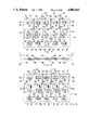
- FIG. 2 is an enlarged top plan view, as seen along line 2--2 of FIG. 1, of the fuel rod grid having the fuel rod engaging spring structures of the present invention, showing the grid removed from the fuel assembly.
- FIG. 3 is an enlarged fragmentary top plan view of the lower right corner of the grid of FIG. 2.
- FIGS. 4 and 5 are elevational views of end portions of the outer straps which meet to form the corner of the grid as seen along respective lines 4--4 and 5--5 of FIG. 3.
- FIG. 6 is an enlarged fragmentary top plan view of the inner strap of one set thereof in the grid of FIG. 2 which interfits with the inner strap of the other set thereof shown in FIG. 9.
- FIG. 7 is a side elevational view as seen along line 7--7 of FIG. 6 from one side of the inner strap in the one set thereof.
- FIG. 8 is another side elevational view as seen along line 8--8 of FIG. 6 from an opposite side of the inner strap in the one set thereof.
- FIG. 9 is an enlarged fragmentary top plan view of the inner strap of the other set thereof in the grid of FIG. 2 which interfits with the inner strap of the one set thereof shown in FIG. 6.
- FIG. 10 is a side elevational view as seen along line 10--10 of FIG. 9 from one side of the inner strap in the other set thereof.
- FIG. 11 is another side elevational view as seen along line 11--11 of FIG. 9 from an opposite side of the inner strap in the other set thereof.
- FIG. 12 is a fragmentary portion of the side elevational view in FIG. 11 of the inner strap in the other set thereof.
- FIG. 13 is an end elevational view as seen along line 13--13 of FIG. 12, showing one set of the dimples and the spring structure on the inner strap.
- FIG. 14 is a sectional view taken along line 14--14 of FIG. 12, showing the same set of dimples and spring structure of the inner strap as seen in FIG. 13.
- FIG. 15 is an enlarged sectional view taken along line 15--15 of FIG. 12, showing the curvature of the leg members of the spring structure of the inner strap.
- FIG. 16 is an enlarged sectional view taken along line 1613 16 of FIG. 12, showing the curvature of one of the dimples on the inner strap.
- FIG. 17 is an enlarged sectional view taken along line 17--17 of FIG. 12, showing the curvature of the cross member of the spring structure on the inner strap.
- FIG. 18 is another enlarged sectional view taken along line 18--18 of FIG. 12, showing the curvature of leg and cross members of the spring structure on the inner strap.
- FIG. 19 is an enlarged fragmentary top plan view of a modified version of the inner strap of one set thereof in the grid of FIG. 2 which interfits with the modified version of the inner strap of the other set thereof in FIG. 22.
- FIG. 20 is a side elevational view as seen along line 20--20 of FIG. 19 from one side of the modified inner strap in the one set thereof.
- FIG. 21 is another side elevational view as seen along line 21--21 of FIG. 19 from an opposite side of the modified inner strap in the one set thereof.
- FIG. 22 is an enlarged fragmentary top plan view of a modified version of the inner strap of the other set thereof in the grid of FIG. 2 which interfits with the modified version of the inner strap of the one set thereof in FIG. 19.
- FIG. 23 is a side elevational view as seen along line 2313 23 of FIG. 22 from one side of the modified inner strap in the other set thereof.
- FIG. 24 is another side elevational view along line 2413 24 of FIG. 22 from an opposite side of the modified inner strap in the other set thereof.
- FIG. 25 is an enlarged fragmentary top plan view of another modified version of the inner strap of either one or the other sets thereof in the grid of FIG. 2.
- FIG. 26 is a side elevational view as seen along line 2613 26 of FIG. 25 from one side of the other modified version of inner strap.
- FIG. 27 is another side elevational view as seen along line 2713 27 of FIG. 25 from an opposite side of the modified version of the inner strap.
- FIG. 28 is a fragmentary portion of the side elevational view in FIG. 21 of the modified inner strap in the one set thereof.
- FIG. 29 is an end elevational view as seen along line 29--29 of FIG. 28 showing one set of modified dimples and the spring structure on the modified inner strap.
- FIG. 30 is a sectional view taken along line 30--30 of FIG. 28, showing the same set of modified dimples and spring structue as seen in FIG. 29.
- FIG. 31 is an enlarged sectional view taken along line 31--31 of FIG. 28, showing the curvature of one of the modified dimples on the modified inner strap.
- FIG. 32 is an enlarged sectional view taken along line 32--32 of FIG. 28, showing the curvature of the one of the modified dimples on the modified inner strap from a different angle than seen in FIG. 31.
- FIG. 33 is an enlarged sectional view taken along line 33--33 of FIG. 28, showing the curvature of the cross member of the spring structure of the modified strap.
- FIG. 34 is an enlarged sectional view taken along line 34--34 of FIG. 28, showing the curvature of one of the modified dimples and the cross member of the spring structure of the modified strap.
- FIG. 35 is a fragmentary portion of the side elevational view in FIG. 24 of the modified inner strap in the other set thereof.
- FIG. 36 an end elevational view as seen along line 36--36 of FIG. 35, showing the other set of modified dimples and the spring structure on the modified inner strap.
- FIG. 37 is a sectional view taken along line 37--37 of FIG. 35, showing the same set of modified dimples and spring structures as seen in FIG. 36.
- FIG. 38 is an enlarged sectional view taken along line 38--38 of FIG. 35, showing the curvature of one of the modified dimples on the modified inner strap.
- FIG. 39 is an enlarged sectional view taken along line 39--39 of FIG. 35, showing the curvature of the one of the modified dimples on the modified inner strap from a different angle than seen in FIG. 38.
- FIG. 40 an enlarged sectional view taken along line 40--40 of FIG. 35, showing the curvature of the cross member of the spring structure of the modified strap.
- FIG. 41 is an enlarged sectional view taken along line 41--41 of FIG. 35, showing the curvatures of one of the modified dimples and cross member of the spring structure of the modified strap.
- FIG. 42 is a fragmentary portion of the side elevational view in FIG. 27 of the other modified inner strap of one or the other sets thereof.
- FIG. 43 is an end elevational view as seen along line 43--43 of FIG. 42, showing the set of modified dimples and the spring structure of the other modified inner strap.
- FIG. 44 is a sectional view taken along line 44--44 of FIG. 42, showing the same set of modified dimples and spring as seen in FIG. 43.
- FIG. 45 is an enlarged sectional view taken along line 45--45 of FIG. 42, showing the curvature of one of the modified dimples on the modified inner strap.
- FIG. 46 is an enlarged sectional view taken along line 46--46 of FIG. 42, showing the curvature of the one of the modified dimples on the other modified inner strap from a different angle than seen in FIG. 45.
- FIG. 47 is an enlarged sectional view taken along line 47--47 of FIG. 42, showing the curvature of the cross member of the spring structure of the modified strap.
- FIG. 48 is an enlarged sectional view taken along line 48--48 of FIG. 42, showing the curvatures of one of the modified dimples and the cross member of the spring structure of the modified strap.
- the fuel assembly 10 is the type used in a pressurized water reactor (PWR) and basically includes a lower end structure or bottom nozzle 12 for supporting the assembly on the lower core plate (not shown) in the core region of a reactor (not shown), and a number of longitudinally extending guide tubes or thimbles 14 which project upwardly from the bottom nozzle 12.
- the assembly 10 further includes a plurality of transverse grids 16 constructed in accordance with the principles of the present invention, as will be described in detail below.
- the grids 16 are axially spaced along and supported by the guide thimbles 14.
- the assembly 10 also includes a plurality of elongated fuel rods 18 transversely spaced and supported in an organized array by the grids 16. Also, the assembly 10 has an instrumentation tube 20 located in the center thereof and an upper end structure or top nozzle 22 attached to the upper ends of the guide thimbles 14. With such arrangement of parts, the fuel assembly 10 forms an integral unit capable of being conveniently handled without damaging the assembly parts.
- each fuel rod 18 in the array thereof in the assembly 10 is held in spaced relationship with one another by the grids 16 spaced along the fuel assembly length.
- Each fuel rod 18 includes nuclear fuel pellets 24 and the opposite ends of the rod are closed by upper and lower end plugs 26,28 to hermetically seal the rod.
- a plenum spring 30 is disposed between the upper end plug 26 and the pellets 24 to maintain the pellets in a tight, stacked relationship within the rod 18.
- the fuel pellets 24 composed of fissile material are responsible for creating the reactive power of the PWR.
- a liquid moderator/coolant such as water, or water containing boron, is pumped upwardly through the fuel assemblies of the core in order to extract heat generated therein for the production of useful work.
- a number of control rods 32 are reciprocally movable in the guide thimbles 14 located at predetermined positions in the fuel assembly 10.
- the top nozzle 22 has associated therewith a rod cluster control mechanism 34 having an internally threaded cylindrical member 36 with a plurality of radially extending flukes or arms 38.
- Each arm 38 is interconnected to a control rod 32 such that the control mechanism 34 is operable to move the control rods 32 vertically in the guide thimbles 14 to thereby control the fission process in the fuel assembly 10, all in a well-known manner.
- the grid 16 includes a plurality of inner and outer straps 40,42 having slots 44 by which the straps are interleaved with one another in an egg-crate configuration to form a matrix of hollow cells 46 and a plurality of openings 48. At the intersections of the straps 40,42, they are suitably secured together, such as by welding.
- the hollow cells 46 of the grid 16 receive therethrough respective ones of the fuel rods 18, whereas the openings 48 of the grid 16 have sleeves 50 inserted therein and attached to the inner straps 40 by which the grid 16 is disposed along and attached to the guide thimbles 14.
- Each cell 46 receiving one fuel rod 18 is defined by pairs of opposing wall sections.
- the wall sections 52 compose the inner straps 40, whereas the wall sections 54 compose the outer straps 42.
- the inner strap wall sections 54 are shared with adjacent cells.
- the wall sections 54 of the outer strap 42 each has a pair of horizontally extending and vertically spaced fuel rod engaging dimples 56 integrally formed thereon in association with each cell 46.
- the wall sections 52 of the inner straps 40 also each has a pair of horizontally extending and vertically spaced fuel rod engaging dimples 58 integrally formed thereon in association with each cell 46.
- each cell 46 formed along the periphery of the grid 16 by the inner and outer straps 40,42 has associated with it four dimples 56,58 and two spring structures 60, whereas each cell 46 formed in the grid 16 by inner straps 40 only has associated with it four dimples 56 and two spring structures 60.
- each fuel rod in each cell 46 is contacted at six circumferentially and axially displaced locations thereon.
- each fuel rod spring engaging structure 60 in accordance with the principles of the present invention, is composed of resiliently yieldable flexible material of the inner straps 40, such as stainless steel metal.
- the components of the spring structure 60 which will be described next, are integrally formed, such as by a conventionally stamping operation, from and on each wall section 52 of the inner straps 40 in association with each cell 46 of the grid 16.
- each spring structure 60 includes a pair of laterally spaced elongated spring leg members 62 and
- each leg member 62 has a pair of opposite upper and lower ends 66,688 and is anchored by being integrally and rigidly connected to the upper and lower portions 70,72 of the respective wall section 52 at only the leg member upper and lower ends 66,688.
- Each cross member 64 has a pair of upper and lower opposite ends 74,76 and extends diagonally between and is integrally attached at such respective ends to the leg members 62 of a pair thereof such that the spring structure 60 formed by the leg and cross members 62,64 has an effective length greater than (for instance, two times) the actual length it occupies on each wall section 52 of the inner straps 40.
- each leg member 62 extends generally parallel to one another and in a direction generally parallel to the central longitudinal axis of the respective grid cell 46.
- the cross member 64 is disposed approximately forty-five degrees with respect to the leg members 62 and to the direction of coolant fluid flow through the grid and to the longitudinal axis of the respective grid cell 46.
- each leg member 62 is slightly bowed or arcuate-shaped in its configuration along a longitudinal section through the leg member. Given such curvature, the leg member 62 projects from the plane P of the wall section 52 into its associated one of the cells 46 toward the central longitudinal axis thereof.
- Each cross member 64 is arched or arcuate-shaped in configuration along a longitudinal section of the cross member. Given such configuration, the cross member 64 projects from the leg members 62 away from the wall section 52 a farther distance into the associated cell 46 toward its longitudinal axis than does the leg members 62. At such position, the cross member 64 at its middle point 78 engages the fuel rod 18 received through the cell 46.
- the cross member 64 is capable of resiliently deflecting or yielding in a direction generally orthogonal to and away from the longitudinal axis of the associated cell 46 and toward the wall section 52 upon engagement by a fuel rod when inserted in the cell 46.
- the leg members 62 project from the plane P of the wall section 52 when the cell 46 is unoccupied by a fuel rod 18. However, they are capable of resiliently deflecting back within the wall section plane P due to resilient deflection of the cross member 64 by its engagement with the fuel rod 18 in the cell 46. In such deflected positions, the leg members 62 do not block coolant flow through the grid 16.
- the cross member 64 like the dimples 58 project from the wall section 52 so as to define an open space therebetween which permits unimpeded flow of coolant fluid therethrough and along the fuel rod received in the cell.
- the configuration of the spring structure 60 allows a very low profile, a reduced grid height, and a low spring constant.
- the spring cross member 64 is set forty-five degrees to the direction of coolant fluid flow, but in manufacture is stamped out parallel to the direction of flow.
- the spring structure 60 has the pair of integral flexible spring leg members 62 which allow the spring structure to be compliant without adding to flow blockage.
- the grid 16 can have mixing vanes 80 formed along the top edge of the inner and outer straps 40,42 thereof.
- FIGS. 19-48 there is shown modified versions of dimples 78 on the inner straps 40 of the transverse fuel rod grid 16 of FIG. 2. Since all of the parts of the inner straps 40 illustrated in FIGS. 6-18 are identical to the parts of the inner straps 40 illustrated in FIGS. 19-48 except for the dimples 58 which are now replaced by modified dimples 78, all of these identical parts will not be identified again in FIGS. 19-48.
- Each dimple 78 is made of the same resiliently yieldable material of the straps 40 and integrally formed, such as by a stamping operation, on each wall section 52 thereof of each cell 46. As before, the dimples 78 as located spaced above and below the spring structure 60 on the wall section 52. Also, each dimple 78 extends or projects into the respective grid cell 46 and is arcuate-shaped along a longitudinal section therethrough.
- each dimple 78 is modified to extend in a diagonal orientation with respect to the central longitudinal axis of the respective grid cell 46.
- the diagonal orientation of each dimple 78 is approximately forty-five degrees with respect to the cell longitudinal axis, the same as the angular orientation of the cross member 64 of each spring structure 60.
- the upper and lower dimples 78 are oriented generally parallel to one another. However, the dimples 78 are oriented generally orthogonal or perpendicular to the orientation of the spring structure cross members 64.
- the upper and lower dimples 78 are oriented again generally parallel to one another. This time the dimples 78 are also oriented generally parallel to the orientations of the spring structure cross members 64.
- the upper dimples 78 are oriented generally perpendicular to both the lower dimples 78 and the spring structure cross members 64. It should be readily apparent that the respective orientations of the upper and lower dimples 78 could be reversed with respect to one another and to the cross members 64.
Landscapes
- Physics & Mathematics (AREA)
- Engineering & Computer Science (AREA)
- Plasma & Fusion (AREA)
- General Engineering & Computer Science (AREA)
- High Energy & Nuclear Physics (AREA)
- Fuel Cell (AREA)
Priority Applications (7)
| Application Number | Priority Date | Filing Date | Title |
|---|---|---|---|
| US07/125,514 US4803043A (en) | 1987-05-22 | 1987-11-25 | Nuclear fuel rod grid spring and dimple structures |
| EP88118690A EP0317831B1 (de) | 1987-11-25 | 1988-11-10 | Haltegitter für Kernbrennstäbe |
| DE8888118690T DE3879396D1 (de) | 1987-11-25 | 1988-11-10 | Haltegitter fuer kernbrennstaebe. |
| ES198888118690T ES2040815T3 (es) | 1987-11-25 | 1988-11-10 | Reja de soporte de barras de combustible nuclear. |
| KR1019880015568A KR0121455B1 (ko) | 1987-11-25 | 1988-11-25 | 핵연료봉 지지 격자 |
| JP63296390A JPH01167696A (ja) | 1987-11-25 | 1988-11-25 | 燃料棒格子のスプリング構造 |
| JP005677U JPH1012U (ja) | 1987-11-25 | 1997-07-01 | 燃料棒格子のスプリング構造 |
Applications Claiming Priority (2)
| Application Number | Priority Date | Filing Date | Title |
|---|---|---|---|
| US5399087A | 1987-05-22 | 1987-05-22 | |
| US07/125,514 US4803043A (en) | 1987-05-22 | 1987-11-25 | Nuclear fuel rod grid spring and dimple structures |
Related Parent Applications (1)
| Application Number | Title | Priority Date | Filing Date |
|---|---|---|---|
| US5399087A Continuation-In-Part | 1987-05-22 | 1987-05-22 |
Publications (1)
| Publication Number | Publication Date |
|---|---|
| US4803043A true US4803043A (en) | 1989-02-07 |
Family
ID=22420065
Family Applications (1)
| Application Number | Title | Priority Date | Filing Date |
|---|---|---|---|
| US07/125,514 Expired - Lifetime US4803043A (en) | 1987-05-22 | 1987-11-25 | Nuclear fuel rod grid spring and dimple structures |
Country Status (6)
| Country | Link |
|---|---|
| US (1) | US4803043A (de) |
| EP (1) | EP0317831B1 (de) |
| JP (2) | JPH01167696A (de) |
| KR (1) | KR0121455B1 (de) |
| DE (1) | DE3879396D1 (de) |
| ES (1) | ES2040815T3 (de) |
Cited By (27)
| Publication number | Priority date | Publication date | Assignee | Title |
|---|---|---|---|---|
| US4895698A (en) * | 1988-03-14 | 1990-01-23 | Westinghouse Electric Corp. | Nuclear fuel rod grip with modified diagonal spring structures |
| US4923669A (en) * | 1989-02-21 | 1990-05-08 | Westinghouse Electric Corp. | Nuclear fuel rod grid spring and dimple structures having chamfered edges for reduced pressure drop |
| US4957697A (en) * | 1987-09-10 | 1990-09-18 | Westinghouse Electric Corp. | Nuclear fuel rod support grid with generally S-shaped spring structures |
| US5139736A (en) * | 1991-04-03 | 1992-08-18 | Combustion Engineering, Inc. | Fuel assembly support grid |
| US5331678A (en) * | 1993-04-27 | 1994-07-19 | Combustion Engineering, Inc. | Spacer grid rod support system |
| US5444748A (en) * | 1994-04-04 | 1995-08-22 | Westinghouse Electric Corporation | Grid structure for supporting fuel rods in a nuclear reactor |
| US5488644A (en) | 1994-07-13 | 1996-01-30 | General Electric Company | Spring assemblies for adjoining nuclear fuel rod containing ferrules and a spacer formed of the spring assemblies and ferrules |
| US5519747A (en) | 1994-10-04 | 1996-05-21 | General Electric Company | Apparatus and methods for fabricating spacers for a nuclear fuel rod bundle |
| US5546437A (en) | 1995-01-11 | 1996-08-13 | General Electric Company | Spacer for nuclear fuel rods |
| US5566217A (en) | 1995-01-30 | 1996-10-15 | General Electric Company | Reduced height spacer for nuclear fuel rods |
| US5675621A (en) | 1995-08-17 | 1997-10-07 | General Electric Company | Reduced height flat spring spacer for nuclear fuel rods |
| WO1999001872A3 (en) * | 1997-07-02 | 1999-03-25 | Westinghouse Electric Corp | A nuclear fuel assembly grid with diagonal fuel retaining springs |
| EP0932162A1 (de) * | 1998-01-27 | 1999-07-28 | Siemens Aktiengesellschaft | Abstandhalter für ein Brennelement eines Kernkraftwerkes |
| US6236702B1 (en) * | 1998-02-04 | 2001-05-22 | Korea Atomic Energy Research Institute | Fuel assembly spacer grid with swirl deflectors and hydraulic pressure springs |
| US6278758B1 (en) * | 1998-07-08 | 2001-08-21 | Mitsubishi Heavy Industries, Ltd. | Support grid for a nuclear reactor fuel assembly |
| US6310932B1 (en) * | 2000-10-23 | 2001-10-30 | Westinghouse Electric Company Llc | Fretting resistant spring design |
| US6393087B1 (en) | 1999-06-04 | 2002-05-21 | Korea Atomic Energy Research Institute | Duct-type spacer grid with swirl flow vanes for nuclear fuel assemblies |
| US6421407B1 (en) | 1999-06-11 | 2002-07-16 | Korea Atomic Energy Research Institute | Nuclear fuel spacer grid with dipper vanes |
| US6606369B1 (en) * | 2002-03-06 | 2003-08-12 | Westinghouse Electric Company Llc | Nuclear reactor with improved grid |
| KR100444699B1 (ko) * | 2001-12-26 | 2004-08-21 | 한국수력원자력 주식회사 | 입술형 다목적 핵연료 지지격자체 |
| US6819733B2 (en) | 2002-05-15 | 2004-11-16 | Westinghouse Electric Company Llc | Fuel assembly and associated grid for nuclear reactor |
| US20050226358A1 (en) * | 2002-03-29 | 2005-10-13 | Framatome Anp | Spacer grid for a fuel unit in a nuclear reactor cooled by light water |
| US20090296876A1 (en) * | 2006-12-26 | 2009-12-03 | Areva Np | Spacer grid with saddle-shaped supports and corresponding nuclear fuel assembly |
| US20100317219A1 (en) * | 2009-06-11 | 2010-12-16 | John Mark Myer | Multi-position connector |
| CN102760498A (zh) * | 2012-07-18 | 2012-10-31 | 中国核动力研究设计院 | 用于核燃料组件具有降低勾挂风险的定位格架 |
| WO2013162669A3 (en) * | 2012-04-17 | 2014-01-03 | Babcock & Wilcox Mpower, Inc. | Spacer grids for nuclear reactor |
| US20140376681A1 (en) * | 2013-06-20 | 2014-12-25 | Westinghouse Electric Company Llc | Nuclear fuel assembly having a spacer grid with one or more seamless corners |
Families Citing this family (1)
| Publication number | Priority date | Publication date | Assignee | Title |
|---|---|---|---|---|
| FR2878645B1 (fr) * | 2004-11-30 | 2007-02-09 | Framatome Anp Sas | Grille de maintien de crayons pour assemblage de combustible nucleaire et assemblage corresondant |
Citations (3)
| Publication number | Priority date | Publication date | Assignee | Title |
|---|---|---|---|---|
| US3933584A (en) * | 1973-04-23 | 1976-01-20 | Nuclear Fuel Services, Inc. | Grid for nuclear fuel assembly |
| US4396573A (en) * | 1979-09-07 | 1983-08-02 | Commissariat A L'energie Atomique | Space grate for fuel-elements of nuclear reactors |
| US4692302A (en) * | 1983-12-30 | 1987-09-08 | Westinghouse Electric Corp. | Coolant flow mixer grid for a nuclear reactor fuel assembly |
Family Cites Families (2)
| Publication number | Priority date | Publication date | Assignee | Title |
|---|---|---|---|---|
| US3928131A (en) * | 1969-08-14 | 1975-12-23 | William J Wachter | Grid structure for nuclear reactor fuel assembly |
| DE2642220A1 (de) * | 1976-09-20 | 1978-03-23 | Kraftwerk Union Ag | Abstandshalter fuer kernreaktorbrennelemente |
-
1987
- 1987-11-25 US US07/125,514 patent/US4803043A/en not_active Expired - Lifetime
-
1988
- 1988-11-10 ES ES198888118690T patent/ES2040815T3/es not_active Expired - Lifetime
- 1988-11-10 DE DE8888118690T patent/DE3879396D1/de not_active Expired - Lifetime
- 1988-11-10 EP EP88118690A patent/EP0317831B1/de not_active Expired - Lifetime
- 1988-11-25 KR KR1019880015568A patent/KR0121455B1/ko not_active Expired - Fee Related
- 1988-11-25 JP JP63296390A patent/JPH01167696A/ja active Pending
-
1997
- 1997-07-01 JP JP005677U patent/JPH1012U/ja active Pending
Patent Citations (3)
| Publication number | Priority date | Publication date | Assignee | Title |
|---|---|---|---|---|
| US3933584A (en) * | 1973-04-23 | 1976-01-20 | Nuclear Fuel Services, Inc. | Grid for nuclear fuel assembly |
| US4396573A (en) * | 1979-09-07 | 1983-08-02 | Commissariat A L'energie Atomique | Space grate for fuel-elements of nuclear reactors |
| US4692302A (en) * | 1983-12-30 | 1987-09-08 | Westinghouse Electric Corp. | Coolant flow mixer grid for a nuclear reactor fuel assembly |
Cited By (36)
| Publication number | Priority date | Publication date | Assignee | Title |
|---|---|---|---|---|
| US4957697A (en) * | 1987-09-10 | 1990-09-18 | Westinghouse Electric Corp. | Nuclear fuel rod support grid with generally S-shaped spring structures |
| US4895698A (en) * | 1988-03-14 | 1990-01-23 | Westinghouse Electric Corp. | Nuclear fuel rod grip with modified diagonal spring structures |
| US4923669A (en) * | 1989-02-21 | 1990-05-08 | Westinghouse Electric Corp. | Nuclear fuel rod grid spring and dimple structures having chamfered edges for reduced pressure drop |
| US5139736A (en) * | 1991-04-03 | 1992-08-18 | Combustion Engineering, Inc. | Fuel assembly support grid |
| US5331678A (en) * | 1993-04-27 | 1994-07-19 | Combustion Engineering, Inc. | Spacer grid rod support system |
| US5444748A (en) * | 1994-04-04 | 1995-08-22 | Westinghouse Electric Corporation | Grid structure for supporting fuel rods in a nuclear reactor |
| US5488644A (en) | 1994-07-13 | 1996-01-30 | General Electric Company | Spring assemblies for adjoining nuclear fuel rod containing ferrules and a spacer formed of the spring assemblies and ferrules |
| US5519747A (en) | 1994-10-04 | 1996-05-21 | General Electric Company | Apparatus and methods for fabricating spacers for a nuclear fuel rod bundle |
| US5546437A (en) | 1995-01-11 | 1996-08-13 | General Electric Company | Spacer for nuclear fuel rods |
| US5566217A (en) | 1995-01-30 | 1996-10-15 | General Electric Company | Reduced height spacer for nuclear fuel rods |
| US5675621A (en) | 1995-08-17 | 1997-10-07 | General Electric Company | Reduced height flat spring spacer for nuclear fuel rods |
| WO1999001872A3 (en) * | 1997-07-02 | 1999-03-25 | Westinghouse Electric Corp | A nuclear fuel assembly grid with diagonal fuel retaining springs |
| US6144716A (en) * | 1997-07-02 | 2000-11-07 | Westinghouse Electric Corp. | Nuclear fuel assembly grid with diagonal fuel retaining springs |
| EP0932162A1 (de) * | 1998-01-27 | 1999-07-28 | Siemens Aktiengesellschaft | Abstandhalter für ein Brennelement eines Kernkraftwerkes |
| US6320925B1 (en) * | 1998-01-27 | 2001-11-20 | Siemens Aktiengesellschaft | Space for a fuel assembly of a nuclear power station |
| US6236702B1 (en) * | 1998-02-04 | 2001-05-22 | Korea Atomic Energy Research Institute | Fuel assembly spacer grid with swirl deflectors and hydraulic pressure springs |
| US6278758B1 (en) * | 1998-07-08 | 2001-08-21 | Mitsubishi Heavy Industries, Ltd. | Support grid for a nuclear reactor fuel assembly |
| US6393087B1 (en) | 1999-06-04 | 2002-05-21 | Korea Atomic Energy Research Institute | Duct-type spacer grid with swirl flow vanes for nuclear fuel assemblies |
| US6608881B2 (en) * | 1999-06-04 | 2003-08-19 | Korea Atomic Energy Research Institute | Duct-type spacer grid with swirl flow vane for nuclear fuel assembly |
| US6421407B1 (en) | 1999-06-11 | 2002-07-16 | Korea Atomic Energy Research Institute | Nuclear fuel spacer grid with dipper vanes |
| US6310932B1 (en) * | 2000-10-23 | 2001-10-30 | Westinghouse Electric Company Llc | Fretting resistant spring design |
| KR100444699B1 (ko) * | 2001-12-26 | 2004-08-21 | 한국수력원자력 주식회사 | 입술형 다목적 핵연료 지지격자체 |
| US6606369B1 (en) * | 2002-03-06 | 2003-08-12 | Westinghouse Electric Company Llc | Nuclear reactor with improved grid |
| US20050226358A1 (en) * | 2002-03-29 | 2005-10-13 | Framatome Anp | Spacer grid for a fuel unit in a nuclear reactor cooled by light water |
| US7469030B2 (en) * | 2002-03-29 | 2008-12-23 | Framatome Anp | Spacer grid for a fuel unit in a nuclear reactor cooled by light water |
| US6819733B2 (en) | 2002-05-15 | 2004-11-16 | Westinghouse Electric Company Llc | Fuel assembly and associated grid for nuclear reactor |
| US20090296876A1 (en) * | 2006-12-26 | 2009-12-03 | Areva Np | Spacer grid with saddle-shaped supports and corresponding nuclear fuel assembly |
| US8644446B2 (en) | 2006-12-26 | 2014-02-04 | Areva Np | Spacer grid with saddle-shaped supports and corresponding nuclear fuel assembly |
| US20100317219A1 (en) * | 2009-06-11 | 2010-12-16 | John Mark Myer | Multi-position connector |
| US8062055B2 (en) * | 2009-06-11 | 2011-11-22 | Tyco Electronics Corporation | Multi-position connector |
| WO2013162669A3 (en) * | 2012-04-17 | 2014-01-03 | Babcock & Wilcox Mpower, Inc. | Spacer grids for nuclear reactor |
| US9378852B2 (en) | 2012-04-17 | 2016-06-28 | Bwxt Mpower, Inc. | Spacer grids for nuclear reactor |
| CN102760498A (zh) * | 2012-07-18 | 2012-10-31 | 中国核动力研究设计院 | 用于核燃料组件具有降低勾挂风险的定位格架 |
| CN102760498B (zh) * | 2012-07-18 | 2015-04-22 | 中国核动力研究设计院 | 用于核燃料组件具有降低勾挂风险的定位格架 |
| US20140376681A1 (en) * | 2013-06-20 | 2014-12-25 | Westinghouse Electric Company Llc | Nuclear fuel assembly having a spacer grid with one or more seamless corners |
| US9734923B2 (en) * | 2013-06-20 | 2017-08-15 | Westinghouse Electric Company Llc | Nuclear fuel assembly having a spacer grid with one or more seamless corners |
Also Published As
| Publication number | Publication date |
|---|---|
| ES2040815T3 (es) | 1993-11-01 |
| DE3879396D1 (de) | 1993-04-22 |
| EP0317831A3 (en) | 1990-01-10 |
| EP0317831A2 (de) | 1989-05-31 |
| KR0121455B1 (ko) | 1997-11-20 |
| JPH1012U (ja) | 1998-01-16 |
| JPH01167696A (ja) | 1989-07-03 |
| EP0317831B1 (de) | 1993-03-17 |
| KR890008854A (ko) | 1989-07-12 |
Similar Documents
| Publication | Publication Date | Title |
|---|---|---|
| US4803043A (en) | Nuclear fuel rod grid spring and dimple structures | |
| US4895698A (en) | Nuclear fuel rod grip with modified diagonal spring structures | |
| US4957697A (en) | Nuclear fuel rod support grid with generally S-shaped spring structures | |
| US4923669A (en) | Nuclear fuel rod grid spring and dimple structures having chamfered edges for reduced pressure drop | |
| US4885127A (en) | Nuclear fuel rod support grid with attachable spring and dimple support spacers | |
| US4726926A (en) | Mixing grid | |
| US4692302A (en) | Coolant flow mixer grid for a nuclear reactor fuel assembly | |
| US3379617A (en) | Means for supporting fuel elements in a nuclear reactor | |
| US4585616A (en) | Nuclear fuel spacer grid with improved outer straps | |
| EP0196598B1 (de) | Abstandsgitter eines Kernreaktorbrennelementes | |
| US5434898A (en) | Nuclear fuel assembly | |
| US4544522A (en) | Nuclear fuel assembly spacer | |
| US4125435A (en) | Grid lattice with sliding strap | |
| US4474730A (en) | Nuclear fuel spacer grid | |
| US4585615A (en) | Nuclear fuel spacer grid with improved grid straps | |
| US4659541A (en) | Nuclear fuel rod support grid with improved multiple dimple arrangement | |
| US3674637A (en) | Spacer grid for nuclear reactor fuel element assembly | |
| US3664924A (en) | Nuclear reactor spring ferrule spacer grid | |
| US4571324A (en) | Nuclear fuel assembly spacer | |
| US4028180A (en) | Support grid for fuel elements in a nuclear reactor | |
| US3824153A (en) | Nuclear reactor fuel assembly spacer grid | |
| EP0291736B1 (de) | Kernbrennstoffstabstützgitter | |
| US3813288A (en) | Nuclear reactor fuel assembly spacer grid | |
| USRE30247E (en) | Means for supporting fuel elements in a nuclear reactor | |
| US4606880A (en) | Symmetric blanket nuclear fuel assembly |
Legal Events
| Date | Code | Title | Description |
|---|---|---|---|
| AS | Assignment |
Owner name: WESTINGHOUSE ELECTRIC CORPORATION, WESTINGHOUSE BU Free format text: ASSIGNMENT OF ASSIGNORS INTEREST.;ASSIGNORS:DE MARIO, EDMUND E.;STREET, BOBBY D.;REEL/FRAME:004887/0767;SIGNING DATES FROM 19880104 TO 19880105 Owner name: WESTINGHOUSE ELECTRIC CORPORATION, A CORP. OF PA,P Free format text: ASSIGNMENT OF ASSIGNORS INTEREST;ASSIGNORS:DE MARIO, EDMUND E.;STREET, BOBBY D.;SIGNING DATES FROM 19880104 TO 19880105;REEL/FRAME:004887/0767 |
|
| STCF | Information on status: patent grant |
Free format text: PATENTED CASE |
|
| FPAY | Fee payment |
Year of fee payment: 4 |
|
| FPAY | Fee payment |
Year of fee payment: 8 |
|
| AS | Assignment |
Owner name: WESTINGHOUSE ELECTRIC CO. LLC, PENNSYLVANIA Free format text: ASSIGNMENT OF ASSIGNORS INTEREST;ASSIGNOR:CBS CORPORATION (FORMERLY KNOWN AS WESTINGHOUSE ELECTRIC CORPORATION;REEL/FRAME:010070/0819 Effective date: 19990322 |
|
| FPAY | Fee payment |
Year of fee payment: 12 |