EP0318147A1 - Feu de sécurité monté sur une roue - Google Patents
Feu de sécurité monté sur une roue Download PDFInfo
- Publication number
- EP0318147A1 EP0318147A1 EP88309608A EP88309608A EP0318147A1 EP 0318147 A1 EP0318147 A1 EP 0318147A1 EP 88309608 A EP88309608 A EP 88309608A EP 88309608 A EP88309608 A EP 88309608A EP 0318147 A1 EP0318147 A1 EP 0318147A1
- Authority
- EP
- European Patent Office
- Prior art keywords
- housing
- top housing
- generally circular
- electrical contact
- light source
- Prior art date
- Legal status (The legal status is an assumption and is not a legal conclusion. Google has not performed a legal analysis and makes no representation as to the accuracy of the status listed.)
- Granted
Links
- 239000004020 conductor Substances 0.000 claims description 27
- 230000002093 peripheral effect Effects 0.000 claims description 7
- 238000010586 diagram Methods 0.000 description 2
- 230000000881 depressing effect Effects 0.000 description 1
- 238000000034 method Methods 0.000 description 1
- 230000000284 resting effect Effects 0.000 description 1
Images


Classifications
-
- B—PERFORMING OPERATIONS; TRANSPORTING
- B60—VEHICLES IN GENERAL
- B60Q—ARRANGEMENT OF SIGNALLING OR LIGHTING DEVICES, THE MOUNTING OR SUPPORTING THEREOF OR CIRCUITS THEREFOR, FOR VEHICLES IN GENERAL
- B60Q1/00—Arrangement of optical signalling or lighting devices, the mounting or supporting thereof or circuits therefor
- B60Q1/26—Arrangement of optical signalling or lighting devices, the mounting or supporting thereof or circuits therefor the devices being primarily intended to indicate the vehicle, or parts thereof, or to give signals, to other traffic
- B60Q1/2696—Mounting of devices using LEDs
-
- B—PERFORMING OPERATIONS; TRANSPORTING
- B60—VEHICLES IN GENERAL
- B60Q—ARRANGEMENT OF SIGNALLING OR LIGHTING DEVICES, THE MOUNTING OR SUPPORTING THEREOF OR CIRCUITS THEREFOR, FOR VEHICLES IN GENERAL
- B60Q1/00—Arrangement of optical signalling or lighting devices, the mounting or supporting thereof or circuits therefor
- B60Q1/26—Arrangement of optical signalling or lighting devices, the mounting or supporting thereof or circuits therefor the devices being primarily intended to indicate the vehicle, or parts thereof, or to give signals, to other traffic
- B60Q1/32—Arrangement of optical signalling or lighting devices, the mounting or supporting thereof or circuits therefor the devices being primarily intended to indicate the vehicle, or parts thereof, or to give signals, to other traffic for indicating vehicle sides, e.g. clearance lights
- B60Q1/326—Arrangement of optical signalling or lighting devices, the mounting or supporting thereof or circuits therefor the devices being primarily intended to indicate the vehicle, or parts thereof, or to give signals, to other traffic for indicating vehicle sides, e.g. clearance lights on or for wheels
-
- B—PERFORMING OPERATIONS; TRANSPORTING
- B62—LAND VEHICLES FOR TRAVELLING OTHERWISE THAN ON RAILS
- B62J—CYCLE SADDLES OR SEATS; AUXILIARY DEVICES OR ACCESSORIES SPECIALLY ADAPTED TO CYCLES AND NOT OTHERWISE PROVIDED FOR, e.g. ARTICLE CARRIERS OR CYCLE PROTECTORS
- B62J6/00—Arrangement of optical signalling or lighting devices on cycles; Mounting or supporting thereof; Circuits therefor
- B62J6/20—Arrangement of reflectors, e.g. on the wheel spokes ; Lighting devices mounted on wheel spokes
Definitions
- This invention relates to safety warning lights and and in particular to warning lights for mounting on a wheel of a vehicle or on the person.
- warning lights of the prior art projected a beam of light either perpendicular to the plane of the wheel or radially parallel to the plane of the wheel thus narrowing the viewing angle from which the warning light can be seen.
- the device of the present invention provides a more reliable switching apparatus and a more easily seen light source in which a generally circular bottom housing having a bottom electrical conductor disposed along the inner surface thereof coaxially engages a generally circular top housing.
- the top housing includes a top electrical conductor extending from proximate center thereof to proximate the outer edge thereof that can be rotated with respect to the bottom housing to connect the ends of the two conductors together in the manner of a switch.
- the other end of the top conductor is connected to a light source mounted on the top housing.
- the other end of the bottom conductor is connected to one side of a source of electrical energy.
- the other side of the light source is connected to the other side of the source of electrical energy.
- Means is provided to attaching the device to the valve stem of a tire.
- Additional means is provided to attaching the device to the person's clothing.
- an object of the present invention to provide a warning safety light for mounting on a vehicle.
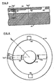
- safety warning light 10 of the present invention comprising a generally circular top housing 12 enclosed and coaxially aligned within a generally circular bottom housing 14.
- Generally circular top housing 12 comprises, basically, a base support member 20 having first tab 22 projecting radially outward from the peripheral edge 24 of top housing 12 with a second tab 26 projecting radially from the peripheral edge 24 of top housing 12 approximately 180 degrees from said first tab 22.
- Top housing 12 further comprises a light emitting diode 28 located proximate the top of housing 12 and having one side electrically connected to one end of top electrical conductor 30 contained within top base support 20.
- the other end of top electrical conductor 30 extends to first tab 22 and is adapted to be attached to, and exposed along, the top side of tab 22 to define top electrical contact 32.
- the other side of light emitting diode 28 is electrically connected to battery contact electrode 34 through conductor 36.
- Contact electrode 34 is adapted to be placed in electrical contact with one side of battery 38.
- Bottom housing 14 comprises, basically, a bottom base support 40 having a generally cylindrical rim 42 adapted to enclose and slide about outer peripheral edge 24 of top housing 12 in the manner of a bearing.
- Cylindrical rim 42 further comprises an inwardly projecting lip 44 proximate the top of rim 42 defining a recess 46 adapted to receive and engage first and second tabs 22 and 26, respectively, of top housing 12.
- a bottom electrical conductor 48 is disposed along the inner surface of bottom housing 40 having one end extending up through rim 42 to terminate along the underside of top lip 44 where it defines second electrical contact 50 adapted to make electrical contact with top electrical contact 32.
- FIG. 2 there is illustrated a top partial cut-away view of safety warning light 10 of the present invention.
- FIG 3 there is illustrated a partial sectional, elevational view of safety warning light 10 of the present invention taken at lines 3-3 of Figure 3.
- bottom housing 14 further comprises two pair of detents 60, 62 and along the underside of lip 44.
- Each pair of detents comprises two detents spaced 180 degrees apart.
- Figure 3 illustrates a set of detents along one side of lip 44.
- detent 60 When top housing 12 is rotated to the "ON" position, detent 60 is adapted to receive the end of bottom conductor 48 defining electrical contact 50 and also receive tab 22 to make contact with electrical contact 32.
- detent 62 is adapted to receive tab 22.
- a pair of oppositely disposed slots 66 and 68 are located in lip 44 which are adapted to permit top housing 12 to be removed from bottom housing 14 when top housing 12 is rotated so that tabs 22 and 26 coincide with slots 66 and 68, respectively.
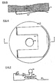
- FIG. 4 there is illustrated a top, partial cut-away view of bottom housing 14 with top housing 12 removed.
- Bottom conductor 48 is shown disposed along the inside surface of bottom housing 14 with battery 38 resting proximate the center of bottom conductor 48 and making electrical contact therewith.
- bottom conductor 48 is raised or offset from the inside surface of bottom housing 14.
- Bottom conductor 48 is preferably fabricated from a resilient, electrically conductive material to allow axial movement to top housing 12 when rotating top housing 12 between detents 60 and 66 and slot 66.
- bottom housing 14 further comprises a threaded hole 70 adapted to receive the threaded valve stem of a bicycle or other vehicle tire.
- bottom housing 14 further comprises a resilient clip 72 adapted to connect to a belt of other piece of wearing apparel.
- bottom housing 14 further illustrating the shape of clip 72 and its relationship to threaded hole 70.
- one side (-) of battery 38 is connected to the appropriate side of light emitting diode 28 through battery contact plate 34 and conductor 36.
- the other side (+) of battery 38 is electrical connected to bottom conductor 48 leading to bottom electrical contact 50.
- top housing 12 is rotated to allow top electrical contact 32 to make contact with bottom contact 50, the electrical circuit is them completed through top conductor 30 to the other side of light emitting diode 28.
- the safety warning light 10 of the present invention is connected to valve stem 80 of tire 86 which is mounted on rim 82 of wheel 88.
- Spokes 84 connect rim 82 to the wheel hub (not shown) common in the art.
- Spokes 84 could be enlarged to define a single circular plate for connecting rim 82 to the wheel hub.
- the single circular plate would then have an opening for access to the tire valve on which would repose safety warning light 10.
- light source 28 would be viewable in a 360 degree horizontal plane about the wheel as the it rotates.
- battery 38 is first placed on top of bottom electrical conductor 48 with the correct polarity in electrical contact therewith.
- Top housing 12 is them place on top of bottom housing 14 with tabs 22 and 26 aligned, respectively, with slots 66 and 68 in lip 44 of bottom housing 14.
- Top housing 12 is them pushed axially downwards, depressing the raised portion of bottom conductor 48, and rotated until tab 22 is aligned with detent 62, i.e., the "ON" position, and then released.
- top housing 12 is again pushed axially downward and rotated until tab 22 is aligned with detent 60, i.e., the "OFF" position, and then released.
Landscapes
- Engineering & Computer Science (AREA)
- Mechanical Engineering (AREA)
- Lighting Device Outwards From Vehicle And Optical Signal (AREA)
- Road Signs Or Road Markings (AREA)
- Arrangement Of Elements, Cooling, Sealing, Or The Like Of Lighting Devices (AREA)
- Professional, Industrial, Or Sporting Protective Garments (AREA)
Priority Applications (1)
| Application Number | Priority Date | Filing Date | Title |
|---|---|---|---|
| AT88309608T ATE89656T1 (de) | 1987-11-23 | 1988-10-13 | Am rad befestigtes sicherheitslicht. |
Applications Claiming Priority (2)
| Application Number | Priority Date | Filing Date | Title |
|---|---|---|---|
| US124551 | 1987-11-23 | ||
| US07/124,551 US4800469A (en) | 1987-11-23 | 1987-11-23 | Wheel mounted safety light |
Publications (2)
| Publication Number | Publication Date |
|---|---|
| EP0318147A1 true EP0318147A1 (fr) | 1989-05-31 |
| EP0318147B1 EP0318147B1 (fr) | 1993-05-19 |
Family
ID=22415535
Family Applications (1)
| Application Number | Title | Priority Date | Filing Date |
|---|---|---|---|
| EP88309608A Expired - Lifetime EP0318147B1 (fr) | 1987-11-23 | 1988-10-13 | Feu de sécurité monté sur une roue |
Country Status (5)
| Country | Link |
|---|---|
| US (1) | US4800469A (fr) |
| EP (1) | EP0318147B1 (fr) |
| JP (1) | JPH01166401A (fr) |
| AT (1) | ATE89656T1 (fr) |
| DE (1) | DE3881167T2 (fr) |
Cited By (1)
| Publication number | Priority date | Publication date | Assignee | Title |
|---|---|---|---|---|
| US9296440B2 (en) | 2011-08-16 | 2016-03-29 | Trek Bicycle Corporation | Lighted bicycle wheel hub assembly |
Families Citing this family (47)
| Publication number | Priority date | Publication date | Assignee | Title |
|---|---|---|---|---|
| US4847735A (en) * | 1987-04-30 | 1989-07-11 | Masaki Kawasaki | Fitting structure of safety lamp to wheel |
| USD317055S (en) | 1989-03-27 | 1991-05-21 | Moore Terrence J | Combined spoke-mounted string of bicycle lights and switch therefor |
| US5205640A (en) * | 1991-04-11 | 1993-04-27 | Nuri Co., Ltd. | Miniature flashlight |
| JPH0589002U (ja) * | 1991-08-20 | 1993-12-03 | スタンレー電気株式会社 | 太陽電池付ホイールマーカー |
| JPH0589001U (ja) * | 1991-08-20 | 1993-12-03 | スタンレー電気株式会社 | ホイールマーカー |
| US5158356A (en) * | 1992-02-10 | 1992-10-27 | Guthrie Alan V | Ornamental lamp with internal switch |
| US5278732A (en) * | 1992-10-20 | 1994-01-11 | John Frankum | Bicycle wheel portable light and reflector |
| US5653523A (en) * | 1993-07-15 | 1997-08-05 | Roberts; Thomas J. | Miniature centrifugal lighting assembly |
| US5550721A (en) * | 1995-05-08 | 1996-08-27 | Carmen & Thomas Rapisarda Enterprises | Motion sensitive light and battery assembly switched on and off by the oscillation of a helical spring |
| US5599088A (en) * | 1995-08-21 | 1997-02-04 | Chien; Tseng L. | Flashing footwear light module |
| US5584562A (en) * | 1995-09-05 | 1996-12-17 | Geran; Michael R. | Bicycle wheel with battery powered safety lights |
| GB2310608B (en) * | 1996-02-27 | 1998-08-12 | Hsu Chi Hsueh | Roller blade skate with illuminatable wheel |
| RU2126751C1 (ru) * | 1996-07-09 | 1999-02-27 | Чернов Евгений Иванович | Осветительное устройство для транспортного средства |
| US5800035A (en) * | 1996-10-29 | 1998-09-01 | Aichele; William E. | Wheel lighting apparatus |
| USD397233S (en) | 1997-02-03 | 1998-08-18 | Startronics Solar Lighting II, Inc. | Solar-powered area light |
| USD397470S (en) | 1997-02-03 | 1998-08-25 | Startronics Solar Lighting II, Inc. | Solar-powered area light |
| US6168301B1 (en) * | 1998-04-17 | 2001-01-02 | Marvin R. Martinez | Wheel luminaire |
| US6070997A (en) * | 1999-02-03 | 2000-06-06 | Mjm, Inc. | Waterproof valve stem safety light for vehicles |
| US6168288B1 (en) * | 1999-08-05 | 2001-01-02 | Tektite Industries West Llc | Flashlight with light emitting diodes |
| US6224235B1 (en) * | 1999-09-20 | 2001-05-01 | Pelican Products, Inc. | Marker flashlight |
| WO2001058720A1 (fr) * | 2000-02-10 | 2001-08-16 | Hae Young Lee | Capuchon eclairant destine a une tige de soupape |
| US6299323B1 (en) | 2000-10-13 | 2001-10-09 | Sun Yu | Miniature led flashlight |
| US6402471B1 (en) * | 2000-11-03 | 2002-06-11 | General Electric Company | Turbine blade for gas turbine engine and method of cooling same |
| US6467939B2 (en) | 2001-01-09 | 2002-10-22 | Theory 3, Inc. | Light for vehicle wheels |
| US6685337B2 (en) | 2001-06-22 | 2004-02-03 | Garry W. Klees | Combination flashlight and candle lantern |
| US6612726B1 (en) | 2002-02-08 | 2003-09-02 | Cary Gloodt | Illuminated automobile wheels |
| US6962427B2 (en) * | 2002-02-08 | 2005-11-08 | Gloodt Cary E | Automobile wheel lighting system |
| US6871987B1 (en) * | 2002-03-28 | 2005-03-29 | Kenny F. Morton | Rim illuminating device |
| US6906472B2 (en) * | 2002-09-04 | 2005-06-14 | Cheerine Development (Hong Kong) Ltd. | Articles with flashing lights |
| US7048421B1 (en) | 2003-01-10 | 2006-05-23 | Linda Marie Allen-Atkins | Self-contained light-emitting means for a vehicle |
| US7004598B2 (en) * | 2003-02-18 | 2006-02-28 | Cheerine Development (Hong Kong) Ltd. | Flashing light system with power selection |
| US20040201983A1 (en) * | 2003-04-08 | 2004-10-14 | Sun Yu | Directable beam miniature led flashlight |
| US7170019B2 (en) * | 2003-07-14 | 2007-01-30 | Cheerine Development (Hong Kong), Ltd. | Inertia switch and flashing light system |
| US20050024852A1 (en) * | 2003-07-31 | 2005-02-03 | Wong Wai Kai | Letter flashing system for footwear and personal articles |
| US20050047161A1 (en) * | 2003-08-26 | 2005-03-03 | Mei-Hui Tai | Centrifugal force-activated signal light assembly for vehicles |
| US7057354B2 (en) * | 2003-09-15 | 2006-06-06 | Cheerine Development (Hong Kong) Limited | Frequency controlled lighting system |
| US7067986B2 (en) * | 2003-09-15 | 2006-06-27 | Cheerine Development (Hong Kong) Limited | Frequency controlled lighting system |
| US7029140B2 (en) * | 2003-12-23 | 2006-04-18 | Cheerine Development (Hong Kong) Ltd. | Flashing light system with multiple voltages |
| US20060209536A1 (en) * | 2004-06-16 | 2006-09-21 | Bartels Kurt W | Lighting assembly and a wheel rim including a lighting assembly |
| US7354182B2 (en) * | 2004-06-16 | 2008-04-08 | Kurt Wilson Bartels | Lighting assembly and a wheel rim including a lighting assembly |
| US7229182B2 (en) * | 2005-05-09 | 2007-06-12 | Darren E Schrader | Lighted hoop |
| US7207688B2 (en) * | 2005-08-18 | 2007-04-24 | Wong Wai Yuen | Interactive shoe light device |
| US20080036165A1 (en) * | 2006-08-08 | 2008-02-14 | Roger Reinson | Skateboard Riser Light |
| WO2008121883A1 (fr) * | 2007-04-02 | 2008-10-09 | The Coleman Company, Inc. | Eclairage de bicyclette avec fixation |
| US20130208491A1 (en) * | 2011-11-16 | 2013-08-15 | Charles E. Franklin | Stem light |
| US9140416B2 (en) * | 2012-07-18 | 2015-09-22 | Krista L. Bostic | Toilet bolt finial night light |
| USD993796S1 (en) * | 2020-04-01 | 2023-08-01 | Strategic Sports Limited | Reflector |
Citations (7)
| Publication number | Priority date | Publication date | Assignee | Title |
|---|---|---|---|---|
| US2518437A (en) * | 1947-08-23 | 1950-08-15 | Butler Brothers | Flashlight |
| US3176092A (en) * | 1962-04-02 | 1965-03-30 | Arthur S Lukasek | Flashlight switch construction with rotatable contact structure |
| US4101955A (en) * | 1976-10-12 | 1978-07-18 | Precision Lamp | Ornamental article with illuminated display |
| DE2818973A1 (de) * | 1978-04-28 | 1979-11-08 | Siemens Ag | Elektrische dauerleuchte |
| EP0010279A1 (fr) * | 1978-10-20 | 1980-04-30 | Gipelec S.A. | Lanterne alimentée par une pile électrique |
| US4220985A (en) * | 1978-02-03 | 1980-09-02 | Hiroshi Hukuba | Illumination device |
| US4417299A (en) * | 1982-03-22 | 1983-11-22 | Rupp John W | Fishing pole light |
Family Cites Families (15)
| Publication number | Priority date | Publication date | Assignee | Title |
|---|---|---|---|---|
| US2382832A (en) * | 1944-04-14 | 1945-08-14 | Thornton Charles Warren | Signal device for vehicles |
| GB774386A (en) * | 1953-12-31 | 1957-05-08 | Bluemel Brothers Ltd | Improvements in or relating to portable battery and cycle electric lamps |
| US2852632A (en) * | 1955-07-05 | 1958-09-16 | Electric Storage Battery Co | Flashlight construction |
| US2852633A (en) * | 1955-07-05 | 1958-09-16 | Electric Storage Battery Co | Flashlight construction |
| US2811633A (en) * | 1956-08-03 | 1957-10-29 | Albin A Bjork | Safety bicycle light |
| US3789208A (en) * | 1972-09-18 | 1974-01-29 | E Lewis | Skate wheel attachment |
| US3820852A (en) * | 1973-06-06 | 1974-06-28 | Beatrice Foods Co | Spoke mountable display device with integral bracket |
| US3987409A (en) * | 1974-09-26 | 1976-10-19 | Freeman Anthony L | Vehicle signal light |
| US4176390A (en) * | 1977-02-04 | 1979-11-27 | Galbert-French, Inc. | Light |
| US4135229A (en) * | 1977-09-01 | 1979-01-16 | Esteban Modurkay | Safety device for use on a bicycle wheel |
| US4383244A (en) * | 1979-10-31 | 1983-05-10 | Knauff Robert J | Pseudo multi light display device and generator therefor |
| US4323879A (en) * | 1980-10-10 | 1982-04-06 | Kelley Dale T | Bicycle safety flasher with optional mounting means for other uses |
| US4398237A (en) * | 1982-01-21 | 1983-08-09 | Doyel John S | Miniature battery-operated light |
| US4523259A (en) * | 1983-12-23 | 1985-06-11 | Dorsett Danny R | Bolt-light bulb combination |
| US4562516A (en) * | 1985-01-28 | 1985-12-31 | Chastain Edward H | Illuminating spinner |
-
1987
- 1987-11-23 US US07/124,551 patent/US4800469A/en not_active Expired - Lifetime
-
1988
- 1988-10-13 DE DE8888309608T patent/DE3881167T2/de not_active Expired - Fee Related
- 1988-10-13 AT AT88309608T patent/ATE89656T1/de not_active IP Right Cessation
- 1988-10-13 EP EP88309608A patent/EP0318147B1/fr not_active Expired - Lifetime
- 1988-11-08 JP JP63280555A patent/JPH01166401A/ja active Pending
Patent Citations (7)
| Publication number | Priority date | Publication date | Assignee | Title |
|---|---|---|---|---|
| US2518437A (en) * | 1947-08-23 | 1950-08-15 | Butler Brothers | Flashlight |
| US3176092A (en) * | 1962-04-02 | 1965-03-30 | Arthur S Lukasek | Flashlight switch construction with rotatable contact structure |
| US4101955A (en) * | 1976-10-12 | 1978-07-18 | Precision Lamp | Ornamental article with illuminated display |
| US4220985A (en) * | 1978-02-03 | 1980-09-02 | Hiroshi Hukuba | Illumination device |
| DE2818973A1 (de) * | 1978-04-28 | 1979-11-08 | Siemens Ag | Elektrische dauerleuchte |
| EP0010279A1 (fr) * | 1978-10-20 | 1980-04-30 | Gipelec S.A. | Lanterne alimentée par une pile électrique |
| US4417299A (en) * | 1982-03-22 | 1983-11-22 | Rupp John W | Fishing pole light |
Cited By (1)
| Publication number | Priority date | Publication date | Assignee | Title |
|---|---|---|---|---|
| US9296440B2 (en) | 2011-08-16 | 2016-03-29 | Trek Bicycle Corporation | Lighted bicycle wheel hub assembly |
Also Published As
| Publication number | Publication date |
|---|---|
| US4800469A (en) | 1989-01-24 |
| ATE89656T1 (de) | 1993-06-15 |
| JPH01166401A (ja) | 1989-06-30 |
| EP0318147B1 (fr) | 1993-05-19 |
| DE3881167D1 (de) | 1993-06-24 |
| DE3881167T2 (de) | 1993-09-02 |
Similar Documents
| Publication | Publication Date | Title |
|---|---|---|
| US4800469A (en) | Wheel mounted safety light | |
| US5993022A (en) | Multi-pivot flashlight | |
| US3706882A (en) | Emergency signal light with magnetic contacts | |
| US20030021108A1 (en) | Beacon light | |
| US5392200A (en) | Circuit for providing illumination on a motor vehicle wheel | |
| US3784809A (en) | Emergency rotating warning lamp | |
| US4225848A (en) | Electric lighting system for bicycle wheels | |
| US3117302A (en) | Rotating signal light | |
| US3781538A (en) | Emergency warning lamp | |
| US6572251B1 (en) | Light emitting assembly for vehicle wheel | |
| US6082871A (en) | Ceiling light | |
| US4921429A (en) | Rotatable bulb socket assembly | |
| US4124880A (en) | Rotating signal light | |
| US6059431A (en) | Wheel mounted safety light | |
| EP0610681A3 (en) | Contact holder for a socket or for a plug of an electrical connector. | |
| US6309085B1 (en) | Lamp support for emergency light fixture | |
| US2772349A (en) | Illuminating apparatus | |
| US20050047161A1 (en) | Centrifugal force-activated signal light assembly for vehicles | |
| US6247829B1 (en) | Interchangeable lamp apparatus having a detachable plug | |
| US20030031019A1 (en) | Light-emitting structure for tires | |
| CA1249862A (fr) | Lampe de lecture et de courtoisie pour interieur de vehicule | |
| JPH02288117A (ja) | ステアリングホイールのスイッチ付ノブ | |
| EP0199594A3 (fr) | Contacts d'interrupteur pour courant fort | |
| JPH0231330Y2 (fr) | ||
| EP1445849A2 (fr) | Moteur |
Legal Events
| Date | Code | Title | Description |
|---|---|---|---|
| PUAI | Public reference made under article 153(3) epc to a published international application that has entered the european phase |
Free format text: ORIGINAL CODE: 0009012 |
|
| AK | Designated contracting states |
Kind code of ref document: A1 Designated state(s): AT BE CH DE ES FR GB GR IT LI LU NL SE |
|
| 17P | Request for examination filed |
Effective date: 19891028 |
|
| 17Q | First examination report despatched |
Effective date: 19910718 |
|
| GRAA | (expected) grant |
Free format text: ORIGINAL CODE: 0009210 |
|
| AK | Designated contracting states |
Kind code of ref document: B1 Designated state(s): AT BE CH DE ES FR GB GR IT LI LU NL SE |
|
| PG25 | Lapsed in a contracting state [announced via postgrant information from national office to epo] |
Ref country code: SE Effective date: 19930519 Ref country code: LI Effective date: 19930519 Ref country code: FR Effective date: 19930519 Ref country code: AT Effective date: 19930519 Ref country code: GR Free format text: LAPSE BECAUSE OF FAILURE TO SUBMIT A TRANSLATION OF THE DESCRIPTION OR TO PAY THE FEE WITHIN THE PRESCRIBED TIME-LIMIT Effective date: 19930519 Ref country code: NL Effective date: 19930519 Ref country code: BE Effective date: 19930519 Ref country code: ES Free format text: THE PATENT HAS BEEN ANNULLED BY A DECISION OF A NATIONAL AUTHORITY Effective date: 19930519 Ref country code: CH Effective date: 19930519 Ref country code: IT Free format text: LAPSE BECAUSE OF FAILURE TO SUBMIT A TRANSLATION OF THE DESCRIPTION OR TO PAY THE FEE WITHIN THE PRESCRIBED TIME-LIMIT;WARNING: LAPSES OF ITALIAN PATENTS WITH EFFECTIVE DATE BEFORE 2007 MAY HAVE OCCURRED AT ANY TIME BEFORE 2007. THE CORRECT EFFECTIVE DATE MAY BE DIFFERENT FROM THE ONE RECORDED. Effective date: 19930519 |
|
| REF | Corresponds to: |
Ref document number: 89656 Country of ref document: AT Date of ref document: 19930615 Kind code of ref document: T |
|
| REF | Corresponds to: |
Ref document number: 3881167 Country of ref document: DE Date of ref document: 19930624 |
|
| REG | Reference to a national code |
Ref country code: CH Ref legal event code: PL |
|
| EN | Fr: translation not filed | ||
| PG25 | Lapsed in a contracting state [announced via postgrant information from national office to epo] |
Ref country code: LU Free format text: LAPSE BECAUSE OF NON-PAYMENT OF DUE FEES Effective date: 19931031 |
|
| NLV1 | Nl: lapsed or annulled due to failure to fulfill the requirements of art. 29p and 29m of the patents act | ||
| PLBE | No opposition filed within time limit |
Free format text: ORIGINAL CODE: 0009261 |
|
| STAA | Information on the status of an ep patent application or granted ep patent |
Free format text: STATUS: NO OPPOSITION FILED WITHIN TIME LIMIT |
|
| 26N | No opposition filed | ||
| PGFP | Annual fee paid to national office [announced via postgrant information from national office to epo] |
Ref country code: GB Payment date: 19941004 Year of fee payment: 7 |
|
| PGFP | Annual fee paid to national office [announced via postgrant information from national office to epo] |
Ref country code: DE Payment date: 19941010 Year of fee payment: 7 |
|
| PG25 | Lapsed in a contracting state [announced via postgrant information from national office to epo] |
Ref country code: GB Effective date: 19951013 |
|
| GBPC | Gb: european patent ceased through non-payment of renewal fee |
Effective date: 19951013 |
|
| PG25 | Lapsed in a contracting state [announced via postgrant information from national office to epo] |
Ref country code: DE Effective date: 19960702 |