EP0318165B1 - Dispositif de contrôle de la vitesse de l'élément rotatif pour résonance magnétique nucléaire - Google Patents
Dispositif de contrôle de la vitesse de l'élément rotatif pour résonance magnétique nucléaire Download PDFInfo
- Publication number
- EP0318165B1 EP0318165B1 EP88310272A EP88310272A EP0318165B1 EP 0318165 B1 EP0318165 B1 EP 0318165B1 EP 88310272 A EP88310272 A EP 88310272A EP 88310272 A EP88310272 A EP 88310272A EP 0318165 B1 EP0318165 B1 EP 0318165B1
- Authority
- EP
- European Patent Office
- Prior art keywords
- rotor
- torque
- rotational
- sense
- stator
- Prior art date
- Legal status (The legal status is an assumption and is not a legal conclusion. Google has not performed a legal analysis and makes no representation as to the accuracy of the status listed.)
- Expired
Links
- 239000000523 sample Substances 0.000 description 20
- 238000005481 NMR spectroscopy Methods 0.000 description 3
- 230000005284 excitation Effects 0.000 description 2
- 230000004044 response Effects 0.000 description 2
- 238000009987 spinning Methods 0.000 description 2
- 238000012935 Averaging Methods 0.000 description 1
- 230000009471 action Effects 0.000 description 1
- 238000004458 analytical method Methods 0.000 description 1
- 238000013016 damping Methods 0.000 description 1
- 230000000694 effects Effects 0.000 description 1
- 239000012530 fluid Substances 0.000 description 1
- 238000000265 homogenisation Methods 0.000 description 1
- 238000007373 indentation Methods 0.000 description 1
- 230000007246 mechanism Effects 0.000 description 1
- 230000004048 modification Effects 0.000 description 1
- 238000012986 modification Methods 0.000 description 1
- 238000001228 spectrum Methods 0.000 description 1
- 230000006641 stabilisation Effects 0.000 description 1
- 238000011105 stabilization Methods 0.000 description 1
- 230000000087 stabilizing effect Effects 0.000 description 1
Images
Classifications
-
- G—PHYSICS
- G01—MEASURING; TESTING
- G01R—MEASURING ELECTRIC VARIABLES; MEASURING MAGNETIC VARIABLES
- G01R33/00—Arrangements or instruments for measuring magnetic variables
- G01R33/20—Arrangements or instruments for measuring magnetic variables involving magnetic resonance
- G01R33/28—Details of apparatus provided for in groups G01R33/44 - G01R33/64
- G01R33/30—Sample handling arrangements, e.g. sample cells, spinning mechanisms
- G01R33/307—Sample handling arrangements, e.g. sample cells, spinning mechanisms specially adapted for moving the sample relative to the MR system, e.g. spinning mechanisms, flow cells or means for positioning the sample inside a spectrometer
Definitions
- the invention is in the field of instrumentation for analysis of samples by nuclear magnetic resonance and particularly relates to mechanisms for rotation of a sample in such instrumentation.
- EP-A-020085 discloses spinner apparatus for rotating a sample under study in an NMR spectrometer, comprising a rotor for holding said sample, a stator surrounding said rotor, said stator forming a gas bearing in which said rotor is levitated by pressurized gas means incorporated in said stator, said stator comprising first torque means imparting rotation in a first sense to said rotor at a preselected area of the rotor.
- the present invention improves on this arrangement by providing second torque means selectively imparting rotational torque to said rotor in a sense opposite said first sense at the same preselected area of the rotor. Performance and response of the sample spinner is thereby improved.
- a positive braking action can be implemented providing a more precise control over the sample spinner, a capability to select the sense of rotation, and to modulate the sample rotation rate and to completely stop sample rotation. Moreover, undesired rotational torques arising from imperfection in practical fluid bearings may be partially or wholly compensated with the selectably controllable torque of either sense.
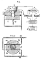
- FIG. 1 there is shown a common arrangement illustrating the present invention.
- the sample spinner system is situated within the bore of a magnet, not shown.
- the sample spinner is surrounded by an RF probe coil 2 which provides RF excitation for resonating nuclei, and subsequently operates to pick up the signal emitted by de-exciting nuclei of the sample.
- the probe coil 2 is shared for these functions through multiplexer 5 operating to alternately connect probe coil 2 to transmitter 6 and receiver 7 for the separate purposes of excitation and signal acquisition.
- Transmitter 6 includes modulation apparatus control by processor 8
- receiver 7 includes a digitization means and phase resolving means.
- Processor 8 controls the multiplexer 5, transmitter 6, and receiver 7 and other apparatus not shown, such as magnetic field stabilization and homogenization equipment, for example.
- the spinner includes rotor 10, which in turn has keel portion 13 and rotor bearing surface 14.
- Stator 15 includes stator bearing surface 16. The sample is contained in a sample well 17 in the rotor 10.
- Stator incorporates jets 19 in the stator bearing surface 16 and radial stabilizing jets 21 directed toward keel portion 13 of rotor 10.
- FIG. 2 indicates one arrangement for the jets 19, where a first pair of jets 19a are disposed to direct a pressurized gas substantially tangentially directed onto bearing surface 14 of the rotor to bear against scalloped indentations 14a. Those jets 19a produce a torque tending to rotate rotor 10 in one sense (counterclockwise, as seen in FIG. 2). A second set of jets, 19b, cause an oppositely-directed torque.
- Separate pressurization circuits 22a and 22b for the respective jets 19a and 19b permit the rotation rate in sense to be controlled through relative pressures at the respective jets.
- a valve 25, and corresponding pressure source, is commonly provided to pneumatically expel the sample and rotor from the system.
Landscapes
- Physics & Mathematics (AREA)
- Condensed Matter Physics & Semiconductors (AREA)
- General Physics & Mathematics (AREA)
- Magnetic Bearings And Hydrostatic Bearings (AREA)
- Container, Conveyance, Adherence, Positioning, Of Wafer (AREA)
Claims (6)
Applications Claiming Priority (2)
| Application Number | Priority Date | Filing Date | Title |
|---|---|---|---|
| US120574 | 1987-11-13 | ||
| US07/120,574 US4806868A (en) | 1987-11-13 | 1987-11-13 | NMR spinner speed control |
Publications (2)
| Publication Number | Publication Date |
|---|---|
| EP0318165A1 EP0318165A1 (fr) | 1989-05-31 |
| EP0318165B1 true EP0318165B1 (fr) | 1991-08-07 |
Family
ID=22391186
Family Applications (1)
| Application Number | Title | Priority Date | Filing Date |
|---|---|---|---|
| EP88310272A Expired EP0318165B1 (fr) | 1987-11-13 | 1988-11-01 | Dispositif de contrôle de la vitesse de l'élément rotatif pour résonance magnétique nucléaire |
Country Status (4)
| Country | Link |
|---|---|
| US (1) | US4806868A (fr) |
| EP (1) | EP0318165B1 (fr) |
| JP (1) | JPH01155252A (fr) |
| DE (1) | DE3864125D1 (fr) |
Families Citing this family (15)
| Publication number | Priority date | Publication date | Assignee | Title |
|---|---|---|---|---|
| FR2628213B1 (fr) * | 1988-03-01 | 1990-06-22 | Sadis Bruker Spectrospin Sa | Sonde perfectionnee pour mesures spectrometriques de resonances magnetiques aux tres hautes temperatures |
| US5202633A (en) * | 1990-11-01 | 1993-04-13 | Doty Scientific, Inc. | High temperature nmr sample spinner |
| US5508615A (en) * | 1991-02-25 | 1996-04-16 | Doty; F. David | Supersonic sample spinner |
| US5644235A (en) * | 1995-06-07 | 1997-07-01 | Varian Associates, Inc. | Use of audio signals for monitoring sample spinning speeds in nuclear magnetic spectrometers |
| US5754048A (en) * | 1996-07-17 | 1998-05-19 | Bruker Instruments, Inc. | Method and apparatus for precisely controlling the periodic motion of an object |
| US5886525A (en) * | 1997-03-17 | 1999-03-23 | The United States Of America As Represented By The Secretary Of The Navy | Apparatus and method for performing NMR spectroscopy on solid sample by rotation |
| JP4021402B2 (ja) * | 2003-11-11 | 2007-12-12 | 株式会社日立製作所 | 制御可能な検波部を有する核磁気共鳴装置 |
| JP5046319B2 (ja) * | 2006-08-31 | 2012-10-10 | 株式会社 Jeol Resonance | 細胞・微生物のnmr測定方法及びnmr用プローブ並びにnmr制御装置 |
| JP2009216430A (ja) * | 2008-03-07 | 2009-09-24 | Hitachi Ltd | Nmr用気体軸受およびそれを備えたnmr装置 |
| US8835866B2 (en) * | 2011-05-19 | 2014-09-16 | Fei Company | Method and structure for controlling magnetic field distributions in an ExB Wien filter |
| DE102017220709B4 (de) | 2017-11-20 | 2019-05-29 | Bruker Biospin Ag | MAS-NMR-Rotorsystem mit verbesserter Raumnutzung |
| CN108872290B (zh) * | 2018-04-24 | 2020-02-11 | 厦门大学 | 一种小型核磁共振谱仪自动旋转提升分辨率的方法及装置 |
| JP6857642B2 (ja) * | 2018-12-25 | 2021-04-14 | 日本電子株式会社 | Nmr測定装置及び試料管回転制御方法 |
| JP7065137B2 (ja) * | 2020-03-05 | 2022-05-11 | 日本電子株式会社 | Nmr測定システム及び試料管センタリング方法 |
| DE102020204379B3 (de) | 2020-04-03 | 2021-05-20 | Bruker Switzerland Ag | Magnetisch kompensierter NMR-Rotor und Verfahren zur Auslegung und Herstellung |
Family Cites Families (8)
| Publication number | Priority date | Publication date | Assignee | Title |
|---|---|---|---|---|
| US2960649A (en) * | 1954-06-18 | 1960-11-15 | Bloch Felix | Line narrowing gyromagnetic apparatus |
| US3681683A (en) * | 1970-09-14 | 1972-08-01 | Varian Associates | Gyromagnetic resonance spectrometer utilizing an improved sample spinning and ejecting structure |
| US3746971A (en) * | 1972-04-03 | 1973-07-17 | Us Army | Sample spinning cell for nmr of flowing systems |
| GB1480478A (en) * | 1973-05-21 | 1977-07-20 | Perkin Elmer Ltd | Spinning in a magnetic field |
| JPS5550146A (en) * | 1978-10-06 | 1980-04-11 | Jeol Ltd | Sample turning device for nmr apparatus |
| US4275350A (en) * | 1979-05-29 | 1981-06-23 | Varian Associates, Inc. | Sample spinning mechanism for NMR probes |
| US4446430A (en) * | 1981-08-31 | 1984-05-01 | Monsanto Company | Sample spinner for nuclear magnetic resonance spectrometer |
| US4491276A (en) * | 1982-07-06 | 1985-01-01 | Speeflo Manufacturing Corporation | Electrostatic spray apparatus |
-
1987
- 1987-11-13 US US07/120,574 patent/US4806868A/en not_active Expired - Fee Related
-
1988
- 1988-11-01 DE DE8888310272T patent/DE3864125D1/de not_active Expired - Lifetime
- 1988-11-01 EP EP88310272A patent/EP0318165B1/fr not_active Expired
- 1988-11-04 JP JP63277557A patent/JPH01155252A/ja active Pending
Also Published As
| Publication number | Publication date |
|---|---|
| EP0318165A1 (fr) | 1989-05-31 |
| US4806868A (en) | 1989-02-21 |
| JPH01155252A (ja) | 1989-06-19 |
| DE3864125D1 (de) | 1991-09-12 |
Similar Documents
| Publication | Publication Date | Title |
|---|---|---|
| EP0318165B1 (fr) | Dispositif de contrôle de la vitesse de l'élément rotatif pour résonance magnétique nucléaire | |
| US4254373A (en) | Sensor for generating nuclear magnetic resonance signals | |
| US4739270A (en) | High speed spinner for NMR spectrometer | |
| US7023118B1 (en) | System for controlling a magnetically levitated rotor | |
| US20090306829A1 (en) | Aircraft with transient-discriminating propeller balancing system | |
| US20020047404A1 (en) | Rotor spinning device with a contactless, passive, radial bearing for the spinning rotor | |
| EP0054617B1 (fr) | Paliers magnétiques linéaires | |
| US4201941A (en) | Spinning apparatus for NMR spectrometers | |
| US5170120A (en) | Rotor synchronized cross polarization of solid state nmr | |
| DE69613890T2 (de) | Verfahren zur Vibrationsschätzung für rotierenden Körper in einem statischen Feld | |
| CA2105676C (fr) | Appareil de rotation de tube echantillon rmn | |
| US5254528A (en) | Brake device including magnet and superconductor | |
| JPH09101272A (ja) | 核磁気スペクトロメータ内のサンプル回転速度をモニターするためにオーディオ信号を使用する装置及び方法 | |
| US4464943A (en) | Seeker gyroscope having reduced cross-coupling between rotor spin and precession | |
| WO1999054749A1 (fr) | Spectrometre a cyclage de champ pour rmn assurant le deplacement d'un echantillon sur un trajet circulaire a une vitesse angulaire preetablie | |
| Morrison et al. | Fully suspended, five-axis, three-magnetic-bearing dynamic spin rig with forced excitation | |
| Ormandy et al. | Dynamics of the Oscillogyro | |
| US4084428A (en) | Torque reaction motor performance evaluation | |
| US3225607A (en) | Gyroscope | |
| US3079803A (en) | Fettered gyroscope for flight control of airborne objects | |
| SE8803200D0 (sv) | Anordning for dynamiska provningar av flektarbetshjul | |
| US5936809A (en) | Precision rotator | |
| EP0147389B1 (fr) | Gyroscope chercheur possedant un couplage transversal reduit entre la precession et le spin du rotor | |
| Downey et al. | Arcsecond grating drive mechanism for operation at 4 K | |
| SU1659863A1 (ru) | Устройство дл контрол скорости вращени |
Legal Events
| Date | Code | Title | Description |
|---|---|---|---|
| PUAI | Public reference made under article 153(3) epc to a published international application that has entered the european phase |
Free format text: ORIGINAL CODE: 0009012 |
|
| 17P | Request for examination filed |
Effective date: 19881205 |
|
| AK | Designated contracting states |
Kind code of ref document: A1 Designated state(s): CH DE GB LI |
|
| 17Q | First examination report despatched |
Effective date: 19900801 |
|
| GRAA | (expected) grant |
Free format text: ORIGINAL CODE: 0009210 |
|
| AK | Designated contracting states |
Kind code of ref document: B1 Designated state(s): CH DE GB LI |
|
| REF | Corresponds to: |
Ref document number: 3864125 Country of ref document: DE Date of ref document: 19910912 |
|
| PLBE | No opposition filed within time limit |
Free format text: ORIGINAL CODE: 0009261 |
|
| STAA | Information on the status of an ep patent application or granted ep patent |
Free format text: STATUS: NO OPPOSITION FILED WITHIN TIME LIMIT |
|
| 26N | No opposition filed | ||
| REG | Reference to a national code |
Ref country code: GB Ref legal event code: 746 Effective date: 19970711 |
|
| PGFP | Annual fee paid to national office [announced via postgrant information from national office to epo] |
Ref country code: CH Payment date: 19981027 Year of fee payment: 11 |
|
| PG25 | Lapsed in a contracting state [announced via postgrant information from national office to epo] |
Ref country code: CH Free format text: LAPSE BECAUSE OF NON-PAYMENT OF DUE FEES Effective date: 19991130 Ref country code: LI Free format text: LAPSE BECAUSE OF NON-PAYMENT OF DUE FEES Effective date: 19991130 |
|
| REG | Reference to a national code |
Ref country code: CH Ref legal event code: PL |
|
| REG | Reference to a national code |
Ref country code: GB Ref legal event code: 732E |
|
| REG | Reference to a national code |
Ref country code: GB Ref legal event code: IF02 |
|
| PGFP | Annual fee paid to national office [announced via postgrant information from national office to epo] |
Ref country code: DE Payment date: 20070102 Year of fee payment: 19 |
|
| PGFP | Annual fee paid to national office [announced via postgrant information from national office to epo] |
Ref country code: GB Payment date: 20071128 Year of fee payment: 20 |
|
| PG25 | Lapsed in a contracting state [announced via postgrant information from national office to epo] |
Ref country code: DE Free format text: LAPSE BECAUSE OF NON-PAYMENT OF DUE FEES Effective date: 20080603 |
|
| REG | Reference to a national code |
Ref country code: GB Ref legal event code: PE20 Expiry date: 20081031 |
|
| PG25 | Lapsed in a contracting state [announced via postgrant information from national office to epo] |
Ref country code: GB Free format text: LAPSE BECAUSE OF EXPIRATION OF PROTECTION Effective date: 20081031 |