EP0318269A2 - Revêtement supprimant une radiation électromagnétique - Google Patents
Revêtement supprimant une radiation électromagnétique Download PDFInfo
- Publication number
- EP0318269A2 EP0318269A2 EP88311088A EP88311088A EP0318269A2 EP 0318269 A2 EP0318269 A2 EP 0318269A2 EP 88311088 A EP88311088 A EP 88311088A EP 88311088 A EP88311088 A EP 88311088A EP 0318269 A2 EP0318269 A2 EP 0318269A2
- Authority
- EP
- European Patent Office
- Prior art keywords
- absorber
- radiation
- permittivity
- suppression
- particles
- Prior art date
- Legal status (The legal status is an assumption and is not a legal conclusion. Google has not performed a legal analysis and makes no representation as to the accuracy of the status listed.)
- Withdrawn
Links
- 230000005670 electromagnetic radiation Effects 0.000 title claims abstract description 70
- 239000000463 material Substances 0.000 claims abstract description 145
- 239000002245 particle Substances 0.000 claims abstract description 103
- 239000000203 mixture Substances 0.000 claims abstract description 8
- 239000002344 surface layer Substances 0.000 claims abstract description 6
- UQSXHKLRYXJYBZ-UHFFFAOYSA-N iron oxide Inorganic materials [Fe]=O UQSXHKLRYXJYBZ-UHFFFAOYSA-N 0.000 claims abstract description 4
- 230000005855 radiation Effects 0.000 claims description 113
- 239000002131 composite material Substances 0.000 claims description 74
- 230000035699 permeability Effects 0.000 claims description 71
- 239000004020 conductor Substances 0.000 claims description 39
- 239000011230 binding agent Substances 0.000 claims description 21
- 238000000034 method Methods 0.000 claims description 17
- 239000010410 layer Substances 0.000 claims description 12
- 230000008859 change Effects 0.000 claims description 11
- 230000007423 decrease Effects 0.000 claims description 11
- 229920001577 copolymer Polymers 0.000 claims description 8
- 229920000642 polymer Polymers 0.000 claims description 8
- 239000002904 solvent Substances 0.000 claims description 8
- 229910017052 cobalt Inorganic materials 0.000 claims description 7
- 239000010941 cobalt Substances 0.000 claims description 7
- GUTLYIVDDKVIGB-UHFFFAOYSA-N cobalt atom Chemical compound [Co] GUTLYIVDDKVIGB-UHFFFAOYSA-N 0.000 claims description 7
- XEEYBQQBJWHFJM-UHFFFAOYSA-N Iron Chemical group [Fe] XEEYBQQBJWHFJM-UHFFFAOYSA-N 0.000 claims description 6
- SZVJSHCCFOBDDC-UHFFFAOYSA-N ferrosoferric oxide Chemical compound O=[Fe]O[Fe]O[Fe]=O SZVJSHCCFOBDDC-UHFFFAOYSA-N 0.000 claims description 6
- 238000000576 coating method Methods 0.000 claims description 5
- 239000011248 coating agent Substances 0.000 claims description 4
- 238000002156 mixing Methods 0.000 claims description 4
- 230000008020 evaporation Effects 0.000 claims description 3
- 238000001704 evaporation Methods 0.000 claims description 3
- 238000001125 extrusion Methods 0.000 claims description 3
- 230000005294 ferromagnetic effect Effects 0.000 claims description 3
- 229940056319 ferrosoferric oxide Drugs 0.000 claims description 3
- NDLPOXTZKUMGOV-UHFFFAOYSA-N oxo(oxoferriooxy)iron hydrate Chemical compound O.O=[Fe]O[Fe]=O NDLPOXTZKUMGOV-UHFFFAOYSA-N 0.000 claims description 3
- 229920000098 polyolefin Polymers 0.000 claims description 3
- 239000011347 resin Substances 0.000 claims description 3
- 229920005989 resin Polymers 0.000 claims description 3
- 230000009467 reduction Effects 0.000 claims description 2
- 239000006096 absorbing agent Substances 0.000 claims 39
- 239000006100 radiation absorber Substances 0.000 claims 23
- 239000003795 chemical substances by application Substances 0.000 claims 8
- 229920005573 silicon-containing polymer Polymers 0.000 claims 2
- 230000001629 suppression Effects 0.000 abstract description 165
- 235000013980 iron oxide Nutrition 0.000 abstract 1
- VBMVTYDPPZVILR-UHFFFAOYSA-N iron(2+);oxygen(2-) Chemical class [O-2].[Fe+2] VBMVTYDPPZVILR-UHFFFAOYSA-N 0.000 abstract 1
- 230000000694 effects Effects 0.000 description 25
- 230000005291 magnetic effect Effects 0.000 description 23
- 238000010521 absorption reaction Methods 0.000 description 15
- 230000001066 destructive effect Effects 0.000 description 12
- 238000012216 screening Methods 0.000 description 12
- 239000011238 particulate composite Substances 0.000 description 11
- 230000005684 electric field Effects 0.000 description 10
- 229910052751 metal Inorganic materials 0.000 description 10
- 239000002184 metal Substances 0.000 description 10
- 229910000746 Structural steel Inorganic materials 0.000 description 9
- 230000005540 biological transmission Effects 0.000 description 9
- 230000005415 magnetization Effects 0.000 description 8
- 230000010287 polarization Effects 0.000 description 8
- 238000010438 heat treatment Methods 0.000 description 7
- 238000004458 analytical method Methods 0.000 description 6
- -1 alkyl acrylamides Chemical group 0.000 description 5
- 230000002999 depolarising effect Effects 0.000 description 5
- 230000008569 process Effects 0.000 description 5
- 239000000758 substrate Substances 0.000 description 5
- 238000009826 distribution Methods 0.000 description 4
- 230000014509 gene expression Effects 0.000 description 4
- 230000000977 initiatory effect Effects 0.000 description 4
- 238000005304 joining Methods 0.000 description 4
- 230000000670 limiting effect Effects 0.000 description 4
- 238000004519 manufacturing process Methods 0.000 description 4
- 238000005325 percolation Methods 0.000 description 4
- 230000002829 reductive effect Effects 0.000 description 4
- 230000003068 static effect Effects 0.000 description 4
- 239000013598 vector Substances 0.000 description 4
- CPLXHLVBOLITMK-UHFFFAOYSA-N Magnesium oxide Chemical compound [Mg]=O CPLXHLVBOLITMK-UHFFFAOYSA-N 0.000 description 3
- 239000000853 adhesive Substances 0.000 description 3
- 230000001070 adhesive effect Effects 0.000 description 3
- 239000000470 constituent Substances 0.000 description 3
- 238000004132 cross linking Methods 0.000 description 3
- WHHGLZMJPXIBIX-UHFFFAOYSA-N decabromodiphenyl ether Chemical compound BrC1=C(Br)C(Br)=C(Br)C(Br)=C1OC1=C(Br)C(Br)=C(Br)C(Br)=C1Br WHHGLZMJPXIBIX-UHFFFAOYSA-N 0.000 description 3
- 229920001971 elastomer Polymers 0.000 description 3
- 239000000806 elastomer Substances 0.000 description 3
- 230000003993 interaction Effects 0.000 description 3
- 150000002739 metals Chemical class 0.000 description 3
- FQPSGWSUVKBHSU-UHFFFAOYSA-N methacrylamide Chemical compound CC(=C)C(N)=O FQPSGWSUVKBHSU-UHFFFAOYSA-N 0.000 description 3
- XLOMVQKBTHCTTD-UHFFFAOYSA-N zinc oxide Inorganic materials [Zn]=O XLOMVQKBTHCTTD-UHFFFAOYSA-N 0.000 description 3
- 239000004698 Polyethylene Substances 0.000 description 2
- 235000021355 Stearic acid Nutrition 0.000 description 2
- OKKRPWIIYQTPQF-UHFFFAOYSA-N Trimethylolpropane trimethacrylate Chemical compound CC(=C)C(=O)OCC(CC)(COC(=O)C(C)=C)COC(=O)C(C)=C OKKRPWIIYQTPQF-UHFFFAOYSA-N 0.000 description 2
- 230000002411 adverse Effects 0.000 description 2
- 229910000410 antimony oxide Inorganic materials 0.000 description 2
- 238000013459 approach Methods 0.000 description 2
- 238000005260 corrosion Methods 0.000 description 2
- 230000007797 corrosion Effects 0.000 description 2
- 238000002425 crystallisation Methods 0.000 description 2
- 230000008025 crystallization Effects 0.000 description 2
- 230000001419 dependent effect Effects 0.000 description 2
- 238000013461 design Methods 0.000 description 2
- 230000008030 elimination Effects 0.000 description 2
- 238000003379 elimination reaction Methods 0.000 description 2
- 229920006244 ethylene-ethyl acrylate Polymers 0.000 description 2
- 230000004907 flux Effects 0.000 description 2
- 238000011065 in-situ storage Methods 0.000 description 2
- 238000009434 installation Methods 0.000 description 2
- 239000000395 magnesium oxide Substances 0.000 description 2
- AXZKOIWUVFPNLO-UHFFFAOYSA-N magnesium;oxygen(2-) Chemical compound [O-2].[Mg+2] AXZKOIWUVFPNLO-UHFFFAOYSA-N 0.000 description 2
- 239000006249 magnetic particle Substances 0.000 description 2
- 239000011159 matrix material Substances 0.000 description 2
- 238000005259 measurement Methods 0.000 description 2
- 239000006078 metal deactivator Substances 0.000 description 2
- 239000000178 monomer Substances 0.000 description 2
- OQCDKBAXFALNLD-UHFFFAOYSA-N octadecanoic acid Natural products CCCCCCCC(C)CCCCCCCCC(O)=O OQCDKBAXFALNLD-UHFFFAOYSA-N 0.000 description 2
- 230000010355 oscillation Effects 0.000 description 2
- 230000036961 partial effect Effects 0.000 description 2
- 239000008188 pellet Substances 0.000 description 2
- 229920000573 polyethylene Polymers 0.000 description 2
- 229920000915 polyvinyl chloride Polymers 0.000 description 2
- 239000004800 polyvinyl chloride Substances 0.000 description 2
- 230000001902 propagating effect Effects 0.000 description 2
- 239000008117 stearic acid Substances 0.000 description 2
- 239000000126 substance Substances 0.000 description 2
- 239000011787 zinc oxide Substances 0.000 description 2
- SMZOUWXMTYCWNB-UHFFFAOYSA-N 2-(2-methoxy-5-methylphenyl)ethanamine Chemical compound COC1=CC=C(C)C=C1CCN SMZOUWXMTYCWNB-UHFFFAOYSA-N 0.000 description 1
- NIXOWILDQLNWCW-UHFFFAOYSA-N 2-Propenoic acid Natural products OC(=O)C=C NIXOWILDQLNWCW-UHFFFAOYSA-N 0.000 description 1
- HCILJBJJZALOAL-UHFFFAOYSA-N 3-(3,5-ditert-butyl-4-hydroxyphenyl)-n'-[3-(3,5-ditert-butyl-4-hydroxyphenyl)propanoyl]propanehydrazide Chemical compound CC(C)(C)C1=C(O)C(C(C)(C)C)=CC(CCC(=O)NNC(=O)CCC=2C=C(C(O)=C(C=2)C(C)(C)C)C(C)(C)C)=C1 HCILJBJJZALOAL-UHFFFAOYSA-N 0.000 description 1
- LMYSNFBROWBKMB-UHFFFAOYSA-N 4-[2-(dipropylamino)ethyl]benzene-1,2-diol Chemical compound CCCN(CCC)CCC1=CC=C(O)C(O)=C1 LMYSNFBROWBKMB-UHFFFAOYSA-N 0.000 description 1
- HRPVXLWXLXDGHG-UHFFFAOYSA-N Acrylamide Chemical compound NC(=O)C=C HRPVXLWXLXDGHG-UHFFFAOYSA-N 0.000 description 1
- 238000012935 Averaging Methods 0.000 description 1
- RYGMFSIKBFXOCR-UHFFFAOYSA-N Copper Chemical compound [Cu] RYGMFSIKBFXOCR-UHFFFAOYSA-N 0.000 description 1
- 229920002943 EPDM rubber Polymers 0.000 description 1
- 241001149900 Fusconaia subrotunda Species 0.000 description 1
- 244000043261 Hevea brasiliensis Species 0.000 description 1
- 239000004610 Internal Lubricant Substances 0.000 description 1
- CERQOIWHTDAKMF-UHFFFAOYSA-N Methacrylic acid Chemical compound CC(=C)C(O)=O CERQOIWHTDAKMF-UHFFFAOYSA-N 0.000 description 1
- WHNWPMSKXPGLAX-UHFFFAOYSA-N N-Vinyl-2-pyrrolidone Chemical compound C=CN1CCCC1=O WHNWPMSKXPGLAX-UHFFFAOYSA-N 0.000 description 1
- 239000006057 Non-nutritive feed additive Substances 0.000 description 1
- ISWSIDIOOBJBQZ-UHFFFAOYSA-N Phenol Chemical compound OC1=CC=CC=C1 ISWSIDIOOBJBQZ-UHFFFAOYSA-N 0.000 description 1
- 239000004952 Polyamide Substances 0.000 description 1
- 239000004793 Polystyrene Substances 0.000 description 1
- 239000004820 Pressure-sensitive adhesive Substances 0.000 description 1
- 229910000831 Steel Inorganic materials 0.000 description 1
- DAKWPKUUDNSNPN-UHFFFAOYSA-N Trimethylolpropane triacrylate Chemical compound C=CC(=O)OCC(CC)(COC(=O)C=C)COC(=O)C=C DAKWPKUUDNSNPN-UHFFFAOYSA-N 0.000 description 1
- BGYHLZZASRKEJE-UHFFFAOYSA-N [3-[3-(3,5-ditert-butyl-4-hydroxyphenyl)propanoyloxy]-2,2-bis[3-(3,5-ditert-butyl-4-hydroxyphenyl)propanoyloxymethyl]propyl] 3-(3,5-ditert-butyl-4-hydroxyphenyl)propanoate Chemical compound CC(C)(C)C1=C(O)C(C(C)(C)C)=CC(CCC(=O)OCC(COC(=O)CCC=2C=C(C(O)=C(C=2)C(C)(C)C)C(C)(C)C)(COC(=O)CCC=2C=C(C(O)=C(C=2)C(C)(C)C)C(C)(C)C)COC(=O)CCC=2C=C(C(O)=C(C=2)C(C)(C)C)C(C)(C)C)=C1 BGYHLZZASRKEJE-UHFFFAOYSA-N 0.000 description 1
- 239000011358 absorbing material Substances 0.000 description 1
- 238000009825 accumulation Methods 0.000 description 1
- 239000000654 additive Substances 0.000 description 1
- 230000000996 additive effect Effects 0.000 description 1
- 150000001338 aliphatic hydrocarbons Chemical class 0.000 description 1
- 125000000217 alkyl group Chemical group 0.000 description 1
- 229920006125 amorphous polymer Polymers 0.000 description 1
- 230000003466 anti-cipated effect Effects 0.000 description 1
- 150000004945 aromatic hydrocarbons Chemical class 0.000 description 1
- 230000009286 beneficial effect Effects 0.000 description 1
- 125000004432 carbon atom Chemical group C* 0.000 description 1
- 239000000919 ceramic Substances 0.000 description 1
- 238000004891 communication Methods 0.000 description 1
- 238000013329 compounding Methods 0.000 description 1
- 229910052802 copper Inorganic materials 0.000 description 1
- 239000010949 copper Substances 0.000 description 1
- 238000010586 diagram Methods 0.000 description 1
- 230000005292 diamagnetic effect Effects 0.000 description 1
- 239000003989 dielectric material Substances 0.000 description 1
- 150000001993 dienes Chemical class 0.000 description 1
- 239000006185 dispersion Substances 0.000 description 1
- 230000005288 electromagnetic effect Effects 0.000 description 1
- 238000010894 electron beam technology Methods 0.000 description 1
- 230000007613 environmental effect Effects 0.000 description 1
- 230000005293 ferrimagnetic effect Effects 0.000 description 1
- 239000012760 heat stabilizer Substances 0.000 description 1
- UCNNJGDEJXIUCC-UHFFFAOYSA-L hydroxy(oxo)iron;iron Chemical compound [Fe].O[Fe]=O.O[Fe]=O UCNNJGDEJXIUCC-UHFFFAOYSA-L 0.000 description 1
- 230000001771 impaired effect Effects 0.000 description 1
- 230000002452 interceptive effect Effects 0.000 description 1
- JEIPFZHSYJVQDO-UHFFFAOYSA-N iron(III) oxide Inorganic materials O=[Fe]O[Fe]=O JEIPFZHSYJVQDO-UHFFFAOYSA-N 0.000 description 1
- 230000001678 irradiating effect Effects 0.000 description 1
- 230000001788 irregular Effects 0.000 description 1
- 239000007788 liquid Substances 0.000 description 1
- 238000011068 loading method Methods 0.000 description 1
- 229940050561 matrix product Drugs 0.000 description 1
- 239000000155 melt Substances 0.000 description 1
- 238000002844 melting Methods 0.000 description 1
- 230000008018 melting Effects 0.000 description 1
- 238000005065 mining Methods 0.000 description 1
- 229920003052 natural elastomer Polymers 0.000 description 1
- 229920001194 natural rubber Polymers 0.000 description 1
- 239000012811 non-conductive material Substances 0.000 description 1
- QIQXTHQIDYTFRH-UHFFFAOYSA-N octadecanoic acid Chemical compound CCCCCCCCCCCCCCCCCC(O)=O QIQXTHQIDYTFRH-UHFFFAOYSA-N 0.000 description 1
- 230000003534 oscillatory effect Effects 0.000 description 1
- 230000001590 oxidative effect Effects 0.000 description 1
- VTRUBDSFZJNXHI-UHFFFAOYSA-N oxoantimony Chemical compound [Sb]=O VTRUBDSFZJNXHI-UHFFFAOYSA-N 0.000 description 1
- 239000003973 paint Substances 0.000 description 1
- 150000002989 phenols Chemical class 0.000 description 1
- 230000000704 physical effect Effects 0.000 description 1
- 239000004033 plastic Substances 0.000 description 1
- 229920003023 plastic Polymers 0.000 description 1
- 229920001084 poly(chloroprene) Polymers 0.000 description 1
- 229920000058 polyacrylate Polymers 0.000 description 1
- 229920002647 polyamide Polymers 0.000 description 1
- 229920001296 polysiloxane Polymers 0.000 description 1
- 229920002223 polystyrene Polymers 0.000 description 1
- 229920002635 polyurethane Polymers 0.000 description 1
- 239000004814 polyurethane Substances 0.000 description 1
- 238000003825 pressing Methods 0.000 description 1
- 238000012545 processing Methods 0.000 description 1
- 230000004044 response Effects 0.000 description 1
- 230000002441 reversible effect Effects 0.000 description 1
- 239000004065 semiconductor Substances 0.000 description 1
- 239000007787 solid Substances 0.000 description 1
- 238000001228 spectrum Methods 0.000 description 1
- 239000012798 spherical particle Substances 0.000 description 1
- 239000010959 steel Substances 0.000 description 1
- 229920003051 synthetic elastomer Polymers 0.000 description 1
- 229920001169 thermoplastic Polymers 0.000 description 1
- 239000012815 thermoplastic material Substances 0.000 description 1
- 239000004416 thermosoftening plastic Substances 0.000 description 1
- 229940096522 trimethylolpropane triacrylate Drugs 0.000 description 1
- 229910000859 α-Fe Inorganic materials 0.000 description 1
Images


Classifications
-
- H—ELECTRICITY
- H05—ELECTRIC TECHNIQUES NOT OTHERWISE PROVIDED FOR
- H05K—PRINTED CIRCUITS; CASINGS OR CONSTRUCTIONAL DETAILS OF ELECTRIC APPARATUS; MANUFACTURE OF ASSEMBLAGES OF ELECTRICAL COMPONENTS
- H05K9/00—Screening of apparatus or components against electric or magnetic fields
-
- H—ELECTRICITY
- H05—ELECTRIC TECHNIQUES NOT OTHERWISE PROVIDED FOR
- H05K—PRINTED CIRCUITS; CASINGS OR CONSTRUCTIONAL DETAILS OF ELECTRIC APPARATUS; MANUFACTURE OF ASSEMBLAGES OF ELECTRICAL COMPONENTS
- H05K9/00—Screening of apparatus or components against electric or magnetic fields
- H05K9/0073—Shielding materials
- H05K9/0081—Electromagnetic shielding materials, e.g. EMI, RFI shielding
- H05K9/0083—Electromagnetic shielding materials, e.g. EMI, RFI shielding comprising electro-conductive non-fibrous particles embedded in an electrically insulating supporting structure, e.g. powder, flakes, whiskers
Definitions
- the present invention relates to coverings for selected structures which, in the path of electromagnetic radiation, would otherwise cause such electromagnetic radiation to be present significantly in regions where unwanted and, more particularly, to coverings for suppressing such electromagnetic radiation in these regions in selected portions of the electromagnetic spectrum to a selected degree.
- electromagnetic radiation emanating from these sources is subject to encountering various objects and being reflected therefrom or transmitted therethrough to a greater or lesser degree depending on the material or geometrical characteristics of such objects.
- Such radiation is particularly well reflected by those objects which are good electrical conductors such as structures of one sort or another containing metals.
- this reflection or transmission of such electromagnetic radiation places that radiation in regions or locales where it is unwanted.
- electromagnetic radiation emanating from a transmitter arrangement in a distance ranging system which impinges on, and is reflected from, any conducting structures in the immediate vicinity thereof will lead to substantial portions of this radiation being reflected directly back to the receiving arrangement of the system with unwanted effects.
- any digital system operating at high switching rates will be a source of electromagnetic radiation which may not be in any way significantly confined if housed in a non-conductive structure such as a plastic enclosure.
- a typical material arrangement for accomplishing this is a composite material having a dielectric host, or binding, material portion in which are dispersed particles, capable of responding to impinging radiation in selected frequency ranges, these together providing an absorbing composite material.
- Such materials can be provided in various forms including paints or other coatings, sheets to be fastened to an underlying substrate perhaps after being bent to more closely match the substrate shape, preformed material structures to be fastened to a more or less matching underlying substrate, etc.
- host or binder dielectric materials including certain polymers and ceramics, among others.
- particles of various natures have been used including metals, magnetic metals, semiconductors, and ferrites.
- Such composite materials are difficult to apply or fasten to the underlying substrates.
- the proper thickness of the material and its mounting are often very important to provide the desired suppression of electromagnetic radiation.
- the desired characteristics of such coverings can be difficult to achieve uniformly on many kinds of structures with many of these forms of material. These difficulties can be compounded by there often being a need to minimize the number of joinings of such material so that rain or other contaminates cannot reach the underlying substrate, and to reduce installation cost.
- the desire to have suppression at some frequencies of incident radiation, but not at others, and to a selected degree requires particulates well suited to those selected frequency ranges. Particles are often needed in such quantities to assure reaching the degree of suppression desired that the weight of the absorbing material arrangement becomes too heavy for the system in which it is used.
- the present invention provides an electromagnetic radiation suppression covering to suppress reflections of incident radiation on structures covered thereby having at least a sheet portion thereof selectively configured.
- a sheet is formed of a selectively conformable, polymeric binding material having one or more particles distributed therein.
- This sheet is characterized by a permittivity and a permeability parameter at least one of which has a significant imaginary part with respect to its real part at selected frequencies.
- This sheet after being conformed to a structure selected to be covered, is of a resulting thickness that is (i) substantially one-fortieth to one-fourth of a wavelength of any electromagnetic radiation propagating in the sheet portion due to that radiation having impinged on the sheet portion containing at least some of the selected frequencies, or (ii) sufficiently great to provide a selected degree of absorption at the selected frequencies in the situation where a sufficiently low degree of impingement surface reflection has been arranged.
- the covering can be any of several configurations, including having a cross section of a continuous loop to form a tubular configuration, and may be provided as a laminate with the lamina having a selected polymeric binding material in at least a sheet portion and selected particles distributed therein.
- the laminate nearest the structure to which the cover is formed may alternatively be an electrical conductor. Gradations in the particulate distribution can provide radiation suppression results like those obtained in a laminar structure. Conformability can be provided by using a shrinkable material, one which shrinks in the presence of sufficient heat or solvent depending on the polymeric binding material chosen. Alternatively, an elastomer which can be mechanically stretched and then released to conform can be chosen for the binding material.
- Electromagnetic radiation emanating from a source as traveling waves moves through a vacuum or through a material medium with a corresponding characteristic velocity and will be reflected at least in part at discontinuities between various media encountered along its path. Where the material medium changes from relatively non-conductive to being quite electrically conductive, the reflected portion will be a very great fraction of the incident electromagnetic radiation impinging on such a conductive medium.
- Such electromagnetic radiation reflections can come about in many forms as is suggested in Figure 1.
- Figure 1 There is shown in that schematic figure a representation of a source of electromagnetic radiation, 10, from which electromagnetic radiation is emanating as suggested by outward-pointing arrows.
- a radiation reflector, 11, which in this figure can be considered a cross section view of an electrical conductor such as a metal cable, rod or wire.
- a portion of the radiation being reflected from conductor 11 reaches a region containing equipment, 12, in which such reflected radiation can lead to electronic signals that are unwanted because they are disruptive, or cause errors, mislead the operator, or lead to other undesirable effects.
- reflector 11 has a surface which appears to be an excellent reflector at the wavelength of the radiation being emanated, there will be specular reflection in which the angle of the instant radiation impinging on reflector 11 with respect to the local surface normal direction is matched by the angle of departure of the reflected radiation. This is suggested by long solid arrows, 13, showing this radiation path.
- Another possibility is non-specular reflection which can result from reflector 11 having a rough surface or a surface having particles embedded therein which are of a size that is on the order of the wavelength of the instant radiation. This reflection is shown by long dashed sequences of arrows, 14, which indicate that the angle of incidence of the impinging radiation may be considerably different than the angle of departure of the reflected radiation.
- the radiation path shown by the short series of arrows, 15, is the result of incident electromagnetic radiation impinging on conductor 11 at a very shallow angle on a surface thereof, which radiation then propagates along the surface of conductor 11 on that side opposite source 10 while continuously radiating in all directions. This includes radiating in such a direction as to lead to a return to equipment 12.
- Various other kinds of surface propagation phenomena are also known to occur.
- An electromagnetic radiation suppression covering can be provided around reflector 11 as a screen to reduce the reflected electromagnetic radiation of selected frequencies which would otherwise occur at region 12 due to incident electromagnetic radiation containing such frequencies having impinged on and then been reflected from such a screened combination.
- Figure 2 shows, for such an arrangement, a portion of a reflector, 11′, (which is an electrical conductor) provided with a portion of such a suppression covering, 16, thereagainst.
- An arrow representing incident electromagnetic radiation, 15′ is shown in Figure 2 for the situation of specular reflection so that the angle, ⁇ of incidence with respect to the local normal axis to the surface of covering 16 is equal to the angle of departure or reflection, from that surface with respect to this same axis.
- the arrangement shown in Figure 2 is an accurate representation for reflector or conductor 11′ being such as to have a flat surface over which suppression covering 16 is provided with a uniform thickness.
- the representation in Figure 2 is also accurate for curved surfaces for purposes of determining the effects of impinging electromagnetic radiation if the radius of curvature for the surface at any location under consideration for these purposes is sufficiently large with respect to the wavelength of the impinging radiation. If so, the impinging radiation behaves as though it were impinging on what is effectively a flat surface.
- the condition which is placed on the surface curvature for it to appear effectively flat is that Im(kr curv ) > 1 where r curv is the radius of curvature of the surface area under question and k is the wave number characterizing the plane wave incident electromagnetic radiation.
- the letters Im stand for the imaginary part of that which is enclosed in the parentheses following these letters, the wave number k typically being a complex number.
- suppression covering 16 is assumed to be directly against conductor 11′ so that conductor 11′ serves as a ground plane (conductive reflector) without any intervening gap or other material being interposed therebetween which would lead to differing results than are obtained in the absence of such gaps or other materials.
- this material may have further effects on such radiation traveling therein through being absorptive to thereby lessen its intensity or energy.
- an analysis of the electromagnetic radiation transmission and reflection situation of Figure 2 can be made on the basis of the well known scattering parameters.
- a version of this analysis defines a propagator matrix at each interface between adjacent pairs of material media, and the matrix product of these matrices can be used to find a transmission coefficient and a reflection coefficient for this system. Since suppression of reflected radiation of some selected wavelength ⁇ o is of primary interest, solutions subject to the condition that this reflection coefficient for the system be zero or thereabout are of primary interest here.
- the transmission coefficient at the surface of conductor 11′ is zero because of its good electrical conductivity.
- This spatial orientation is defined with respect to the plane of incidence which is that plane containing both the incident and reflected wave vectors, these wave vectors being normal to the planar wave fronts and pointing in the direction of energy flow.
- the radiation is defined to have a perpendicular polarization when the electric field is perpendicular to the plane of incidence, and to have a parallel polarization when the field is parallel to the plane of incidence. Radiation having other polarizations can also be represented as a combination of such perpendicular and parallel polarized waves.
- the thickness d for suppression covering 16 becomes d ⁇ /4.
- the thickness of suppression covering 16 is to be a quarter of the wavelength ⁇ of that portion of the electromagnetic radiation propagating in that covering which has been transmitted from the incident radiation impinging on the left-hand surface of covering 16. This remaining portion of the incident electromagnetic radiation impinging on the left-hand surface of suppression covering 16 is reflected. That is, the incident electromagnetic radiation impinging on the left-hand surface of suppression covering 16 is partially reflected and partially transmitted.
- the transmitted portion of the radiation reflects completely from the surface of the left-hand side of conductor 11′ because of its substantial electrical conductivity. If the thickness for suppression covering 16 is ⁇ /4, this radiation reflected from the left-hand surface of conductor 11′ meets the reflected radiation from the left-hand surface of suppression covering 16 in the region to the left of this latter surface in the directly opposite phase so that destructive interference results.
- this solution for the thickness of suppression cover 16 is just that thickness needed for a single rightward or forward transversal of, followed by a corresponding single reverse or leftward transversal of, suppression cover 16 by the transmitted portion of the impinging electromagnetic radiation to result in destructive interference.
- This portion of the radiation which is first transmitted from the left-hand surface of suppression covering 16 in the structural arrangement of Figure 2 and then reflected back through that surface interferes destructively with the portion which is reflected only from the left-hand surface of suppression covering 16.
- this solution is likely to be the thickest value for suppression covering 16 which will be useful in suppressing radiation of incident wavelength ⁇ o since it depends primarily on destructive interference because the reflected portion of the impinging radiation is essentially canceled by a single transversal of the covering 16 material of the transmitted portion of the impinging radiation.
- suppression coverings are undesirable in that they add weight and cost, and are therefore unlikely to be used.
- the thickness d must be a real number, this result means that the permeability must be purely imaginary, or at least in view of this being an approximation, must be quite large relative to its real part.
- the presence of an imaginary part in the permeability or the permittivity is the basis for absorption of electromagnetic radiation energy passing through such material.
- the limiting case for suppression radiation reflections at a selected wavelength ⁇ o just described using a thin suppression covering having large absorption capabilities, as represented by the last equation, is the solution resulting if the covering material "impedance" is much greater than one.
- the impedance will be large.
- the partial reflection of incident radiation from the left-hand surface of suppression covering 16 is a function of the impedance because the reflection coefficient for this interference taken alone is related to the impedance by For the typical situation of air occurring to the left of cover 16, Z o ⁇ 1.
- the amplitude of the electric field part of the partially reflected wave is comparable to the amplitude of the electric field part of the incident wave and there would be a large resulting reflection.
- Destructive interference is required to be provided in such a situation to achieve nearly zero total reflected power.
- the amplitude of the electric field part of the partially reflected wave is comparable to the amplitude of the electric field part of the incident wave.
- the vector sum of the fields in the waves moving to the left away from the left-hand surface of suppression covering 16 must be zero.
- the waves moving to the left away from the left-hand surface include the partially reflected incident wave and the series of waves arising from the partially transmitted incident wave.
- the partially transmitted wave gives rise to a series of waves moving to the left away from the left-hand surface due to multiple reflections at the surfaces of the covering and partial transmission at the left-hand surface of the covering.
- the covering has suppressed the reflection through destructive interference. If the impedence of the suppression covering is much greater than one or much less than one, destructive interference is required to achieve nearly zero total reflection.
- suppression covering 16 which rely on both destructive interference and absorption to eliminate, or nearly eliminate, reflections of electromagnetic radiation impinging on the structural arrangement of Figure 2 in at least selected regions with respect thereto, the foregoing suggests that there must be a careful selection of the material and configuration for suppression covering 16. That is, the constituent materials for suppression covering 16 must be chosen to yield the necessary permittivity and permeability parameters of the material taken as a whole to thereby give the desired reflection result in conjunction with the choice of thickness for that material. However, several other criteria must be met by suppression covering 16 to be suitable in the several situations that can occur for it to serve successfully as a means for screening selected structures which would otherwise cause unwanted reflections of impinging electromagnetic radiation.
- suppression covering 16 should be assured of having intimate contact with a conductive material against the side thereof which is facing the structure to be screened even though such structure may have an irregular surface.
- gaps or other materials interposed between suppression covering 16 and such an electrically conductive surface serving as a ground plane (conductive reflector) may lead to unexpected results in shifting the range of frequencies of impinging electromagnetic radiation which is suppressed or negating such suppression to a significant degree if not altogether.
- suppression covering 16 should be configured in such a manner that it can be retroactively applied around such selected structures to screen them so as to suppress reflection of electromagnetic radiation impinging thereon.
- suppression covering 16 should be applicable about such structures in an effective and economical manner in a way which permits later installation effectively.
- suppression covering 16 in providing such reflection suppression screening about selected structures may have to do so in adverse environments such as weather, a variety of chemical atmospheres, etc. In doing so, suppression covering 16 may be required to maintain a watertight seal, withstand temperature extremes, withstand corrosion, and the like.
- Such a composite material will have a host material, or binding material, in which is distributed one or more selected kinds of particles such that such materials in combination together provide the desired material characteristics for suppression covering 16.
- a binding material, or host material, for such a composite material which can be selectively conformed to a corresponding selected structure can, in many instances, assure that suppression covering 16 will thereby fit tightly against that selected structure if that structure is not too involuted. This will assure that the selected structure, as an electrical conductor, will provide a good ground plane to assure the system in the manner of Figure 2 operates as designed. If the structure is so involuted as to make conforming to it prohibitively difficult, a metal layer can be positioned between the solid structure and suppression covering 16, as shown in Figure 3, to assure that suppression covering 16 is against a good electrical conductor to provide a sufficient ground plane.
- Figure 3 shows a selected structure, 11 ⁇ , in the form of an "angle iron" or pair of steel strips affixed at right angles to one another along the length thereof.
- angle iron Surrounding angle iron 11 ⁇ is a braided metal mesh covering, 17, which is pressed against the surface of angle iron 11 ⁇ by suppression covering, 16a, shown at its end, except those surfaces thereof which form and are immediately adjacent to the included right angle.
- Metal mesh 17 can be formed, for instance, by a tinned copper braid such as Scotch Brand 24 Electro Shield Tape supplied by Minnesota Mining and Manufacturing Company (3M). Alternatives to use of a mesh braid to provide a ground plane would be to metallize the surface of the interior of suppression covering 16a or to fill spaces between the covering and the structure with an electrically conductive sealer.
- a tinned copper braid such as Scotch Brand 24 Electro Shield Tape supplied by Minnesota Mining and Manufacturing Company (3M).
- Alternatives to use of a mesh braid to provide a ground plane would be to metallize the surface of the interior of suppression covering 16a or to fill spaces between the covering and the structure with an electrically conductive sealer.
- suppression covering 16 of mesh against angle iron 11 ⁇ in Figure 3 is accomplished very well by choosing the binding material, or host material, of suppression covering 16a to be capable of being placed over mesh 17 and angle iron 11 ⁇ and shrunken thereagainst in a suitable manner. The result is that suppression covering 16a is selectively conformed through forces internal thereto to angle iron 11 ⁇ about mesh 17 to provide a close fit.
- this kind of arrangement can be used for conforming suppression covering 16 of Figure 2 to a less involuted structure, like that of rod or cable 11 in Figure 1, with the result shown in the cross section view of Figure 4.
- This structure of smoother surface contour allows the elimination of mesh 17 as this suppression covering, 16b, shown at its end, conforms by shrinking due to forces internal thereto directly against the entire surface of conductive rod or cable 11.
- the result in Figure 4 is that suppression covering 16b is conformed about conductive cable 11 in a tight fit thereagainst so that conductor 11, as screened by covering 16b, serves as a ground plane for the structural system of Figure 4.
- a mesh, 17′ could be used in the systems of Figure 4 as is indicated by the dashed lines therein. Mesh 17′ would not be needed, however, if suppression covering 16 forms itself as a result of shrinking with a sufficiently close fit to conductor cable 11.
- the situation described for the structural systems of Figures 3 and 4, having suppression covering shrunken against a conductive base is especially effective for those situations where the structure being screened by the covering has already been formed and is to be installed.
- the suppression covering may be formed as a tube, usually by extrusion, and positioned over and around such a structure selected to be screened thereby, perhaps angle iron 11 ⁇ shown in Figure 3 or conductive rod or cable 11 shown in Figure 4, or some other selected structure.
- This covering is then shrunken against the selected structure by suitable means.
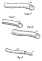
- An end portion of such a tube, again designated 16b, suitable for these purposes is shown in Figure 5A, with the end of the tube shown having a cross section which follows a seamless closed curve.
- the structure selected to be screened may be already installed between supports making it difficult or impossible to position a tube with a closed circumference, such as that shown in Figure 5A, thereover, at least without extensive disassembly of the installed structure.
- suppression covering 16b of Figure 5A can be divided or slit parallel to its lengthwise axis such that the structure that was a tube can now have the wall thereof spread apart from the slit at which it has been divided as in the end portion version, 16c, shown in Figure 5B. This arrangement can then be positioned about and wrapped around the installed structure selected for screening.
- a shape like that of tube-like covering 16c in Figure 5B could be also extruded but with a lengthwise opening along a side thereof. Again, this suppression covering arrangement could be spread apart and then positioned about and wrapped around the installed structure selected for screening.
- a locking means could be extruded along the lengthwise opening in this arrangement so that the positioning of the tube around the structure selected for screening is maintained after being wrapped thereabout. To do so, one edge of the lengthwise opening in this arrangement is, through the locking means, locked to the other to hold the tube-like arrangement in position for further joining steps.
- FIG 5C an end portion of a suppression covering, 16d, is shown with two differently directed, one in and one out, angled wall extensions along an edge of the lengthwise opening. These angled wall extensions can be placed with one inside the other after being wrapped about a selected structure to lock covering 16d in that position.
- Either of the configurations shown in Figures 5B and 5C, or other similar split tube configurations, can be finished as a complete tube through joining the edge regions on opposite sides of the lengthwise opening together permanently through bonding.
- Such bonding can be accomplished, for instance, with an adhesive, or with a pressure sensitive tape, or with other means strong enough to hold the edge regions together on opposite sides of the lengthwise opening in a fixed relative position during the subsequent shrinking step used to provide conformance of the suppression covering to the structure selected to be screened.
- the suppression covering After such edge joining, the suppression covering would have a cross section which would again follow a closed curve but with a seam.
- a suitable adhesive or pressure sensitive tape to be used with the elevated temperature encountered in heat shrinking may depend on the particular material chosen for binding or host material in the composite material used for the suppression covering.
- a generally satisfactory adhesive and composite material treatment begins with treating the surface of the suppression covering to enable a polar liquid to wet its surface, then coating the surface so treated with a monomer selected from acrylic acid, methacrylic acid and others thereof, acrylamide, methacrylamide, sterically non-hindered tertiary alkyl acrylamides and methacrylamides, secondary alkyl acrylamides and methacrylamides having three or less carbon atoms in the alkyl group, and N-vinyl pyrrolidone.
- a suppression covering can be formed directly about and against the conductor structure which has been selected for screening.
- a conductive wire or cable or rod can have a suppression covering extruded thereabout at the time of fabrication of the screened structure.
- Figure 5D Such an arrangement is shown in Figure 5D where an end portion of a suppression covering, 16e, is shown extruded about an end portion of a conductor, 11′′′. Again, a cross section of suppression covering 16e follows a seamless closed curve.
- suppression covering 16e could be a shrinkable covering like coverings 16b, 16c or 16d, and then be used in a suitable positioning and shrinking process at the time of fabricating a screened conductor such as shown in Figure 5D rather than being extruded therewith.
- the binding or host material will be chosen as a polymeric material which can be selectively caused to shrink after being positioned about a structure selected to be screened so as to be able to conform thereto upon shrinkage due to some shrinkage initiating event.
- Some typical polymeric materials would be those which can be shrunk as a result of a significant application of heat thereto with the initiating event being such an application of heat.
- the heat will usually be applied by convective or conductive means rather than by radiative means as the electromagnetic radiation absorption characteristics of the composite material will usually be determined by the need to suppress radiation reflections at frequencies lower than infrared which will usually not accommodate also choosing the characteristic of sufficient infrared absorption for heating purposes.
- polymeric material would be one which can be shrunk as a result of a solvent being evaporated therefrom with the initiating event being this evaporation of a solvent therefrom.
- polymeric material be an elastomer which is mechanically stretched over and around the structure selected to be screened and then released to thereby conform to such structures.
- each of these forms of suppression covering conformance the extent of a surface in at least one direction is reduced, i.e. shrunk, to result in a selective conformance of the suppression covering about the corresponding structure selected to be screened.
- the only forces acting to reduce this surface extent are forces internal to the polymeric material, that is, molecular forces, which are given effect through the corresponding initiating event.
- suppression coverings 16, 16a, 16b, 16c or 16d both as to its shrinkage properties and as to its electrical and magnetic properties (only these latter properties need be considered for the material of covering 16e) in conjunction with the electromagnetic properties of the particles distributed therein.
- the suppression of reflection of electromagnetic radiation of selected frequencies that has impinged upon a structure, in at least some regions with respect thereto, which has been screened by such a composite material will be negligible for only certain selected combinations of the permittivity or permeability, or both, of this composite material and its final thickness after being conformed to the selected structure.
- the final thickness of a suppression covering resulting after conformance, or shrinking can be predicted on the basis that the volume of the shrinkable polymeric binding or host material, with the selected particulate or particulates distributed therein, will remain essentially constant from the initial state the covering was in before shrinking to the final shrunken state (although that volume may change during the actual shrinking).
- the final thickness of this covering can be successfully predicted.
- the small size of the polymeric material molecules relative to the particulates distributed in that material, which together form the composite material results in the properties of the composite being independent of the particulates in its final crystalline state. Though the rate of crystallization may be affected by the particulate types distributed in the polymeric material because of different heat capacities for different kinds of particles, and the like, the final crystallization state of the polymeric material will essentially be the same whatever the particulate type used.
- the choice of the electrical and magnetic properties of the polymeric material and the particulates to be distributed therein must be carefully made if the composite material is to have the desired permittivity and permeability planned for a given covering thickness to yield the desired negligible reflection of that electromagnetic radiation of selected frequencies having impinged on a structure screened with such composite material.
- the polymeric binding material, or host material will usually not itself have any significant magnetic properties and so will not respond to magnetic fields. As a result, the permeability of this material will usually equal one.
- the permittivity of the polymeric binding material will be significant, and will vary with the choice of material type and with direction therein.
- a polymeric binding or host material which is to be heat shrinkable will be a thermoplastic material which is capable of having a selected stress locked into it.
- Both crystallizable and amorphous polymers or copolymers which can be cross-linked or oriented may be used to lock in stresses. Further, they should be conveniently usable at temperatures below the melt temperature thereof. Thus, melt temperatures should be above ordinary room temperature, typically 95° C to 225° C.
- the crystallizable materials can be selected from the polyolefin polymers and copolymers thereof, these polymers including polyethylene, and polypropolyene, and polyvinyl chloride.
- the amorphous materials can be selected from the silicone, polyacrylate and polystyrene polymers and copolymers.
- a copolymer introduced to provide cross-linking prevents melting of the thermoplastic during heat shrinking.
- such a material can be an elastomer selected from (i) the synthetic elastomers such as the reactive diene polymers including polychloroprenes, EPDM, and the like, and (ii) the natural rubbers.
- Suitable solvents for solvent shrinking can be selected from the aromatic hydrocarbons and the aliphatic hydrocarbons.
- the extruded material can be chosen from among polyvinyl chloride, polyethylene, polyamide or polyurethane.
- the zinc oxide and the magnesium oxide are heat stabilizers for the resin to aid in maintaining its polymeric form, particularly during compounding and fabricating.
- the trimethylol propane triacrylate promotes cross-linking.
- the hindered phenols are for oxidative stability during subsequent use of the suppression covering typically in air, and the metal deactivator is to inhibit corrosion of metal particulates distributed in the binding material.
- the stearic acid is a processing aid serving as an internal lubricant.
- the blend of two similar resins is to provide a better balance of physical properties and processing properties such as tensile strength and flexibility and viscosity.
- the electrical and magnetic properties of the foregoing, and other binding or host materials combine in complicated ways with the electrical and magnetic properties of the particulates distributed therein to provide the electrical and magnetic properties of the composite material.
- the permittivity of the composite material is not a linear combination of the permittivity of the binding or host material weighted by its volume fraction and the permittivity of the particulates weighted by one or more corresponding volume fractions.
- the permeability of the composite material is not a linear combination of a volume fraction weighted binding material permeability (likely to be one) and volume fraction weighted particulate permeability. Such combining on a volume basis provides no recognition of the strong effects provided by differing shaped particles.
- a conductive particle which is small with respect to the wavelength of an electromagnetic plane wave impinging thereon experiences a high frequency alternating electrical field which is essentially uniform across the particle.
- Such a field tends to move electrical charges in the particle back and forth toward the opposite ends thereof in an oscillatory manner as the charge attempts to follow the continually reversing electric field. Movement of electrical charge in time is an electric current which flows back and forth in the particle leading to energy losses therein due to the electrical resistance of the particle with particle heating the result.
- the loss of energy from the impinging electromagnetic wave may be significantly different than what it would be for a spherical particle.
- This induced field, the depolarizing field has a strength at a point in the particle which depends on the particle shape since this strength is related to the square of the distance from that point to the locations of the charges.
- a particle which is in the form of a conductive whisker i.e. a long, thin sliver
- An insulating particle with a conductive coating thereabout will also lead to weak depolarizing fields because much of the charge will oscillate back and forth within the coating at the extreme ends with respect to the field direction, but these closely spaced charge distributions at the extreme ends will lead to small resultant fields which will tend to cancel out in intermediate positions in the particle leading to weak depolarizing fields there.
- the electric field part of the radiation at any one time will change across the extent of the particle during an oscillation so that currents are always flowing in the particle and in varying paths.
- These are, in effect, eddy currents giving energy losses due to resistive heating.
- particle size and shape, and the frequency content of the impinging radiation all have an effect on the amount of energy lost by the radiation traveling through a suppression covering having these particles.
- the concentration of particles in the binding or host material also makes a significant difference.
- particle clusters in a yet non-conductive material will occur, with some of the clusters forming local continuous conductive paths or loops.
- the magnetic field part of the impinging radiation traveling in the suppression covering which results in magnetic flux passing through such loops will thereby induce a current in the loops.
- the number of loops present increases rapidly as the percolation threshold is approached.
- the diamagnetic response depends on frequency because more frequent flux reversals through the loops lead to greater radiation energy losses.
- the losses are frequency dependent and further depend on the particle shape and orientation in setting the percolation threshold and so the number of such loops present.
- the magnetic field part of the impinging radiation traveling in the suppression covering also affects any magnetic particles included therein.
- These particles usually have a magnetization which tends to persist in a preferred direction in the particle.
- the magnetic field in the radiation will tend to rotate this magnetization to align with the field direction, and so an alternating magnetic field such as occurs with radiation will tend to cause the magnetization to precess about the preferred magnetization direction. This precession will lead to an energy loss because of the interaction of the magnetization with other domains nearby.
- Such a particle system will have a resonant frequency at which the precessing magnetization is best able to follow the frequency of the alternating magnetic field. The greater the eccentricity of the shape of the particles, the higher this resonant frequency will be, thereby leading to greater losses.
- Conductive magnetic particles are also subject to eddy currents if the wavelength of the electromagnetic radiation is comparable or greater in size than is the particle as indicated above. Such flowing eddy currents will give rise to energy losses as indicated before due to electrical considerations, but these flowing currents will also lead to additional magnetic fields which can affect the loss of energy in impinging radiation traveling in the composite material.
- the prediction of the electrical and magnetic properties of the composite material from the electrical and magnetic properties of both the binding or host material and the particulate type or types to be distributed therein must take into account all of the various factors if the resulting composite material is to have the predicted permittivity and permeability.
- These predictions can be successfully done by combining the electric and magnetic fields in the composite material due to the host material and the particulates distributed therein and by combining the polarizations and magnetizations due to each.
- the composite material permittivity and permeability can then be obtained in terms of the host material and the particulate permittivities and permeabilities on this basis rather than on the basis of merely a volume fraction weighting which ignores effects of particle shape. This combining of these fields as a basis for finding the composite material permittivity and permeability leads to consideration of particle shape, particle orientation, particle distribution, interactive frequency effects and the like.
- the permittivity tensor for the composite material as a whole can be shown to be the following: where f is the volume fraction taken by the distributed particulates in the composite material, ⁇ m and ⁇ p are second order tensors representing the permittivity of the host or binding material and the particulate, respectively, 1 represents a unit second order tensor, and ⁇ ⁇ represents a second order tensor having elements which depend on ⁇ m , ⁇ p and parameters determined by the shapes of the particles in the particulate.
- the first kind of particulate, A has particles of ferroso-ferric oxide ( ⁇ FeO x Fe2O3) having a thin layer of cobalt adsorbed on the surface thereof, shaped in an acicular form having its greatest dimension averaging approximately 0.4 microns.
- the value of x is between 1.0 and 1.5 with the cobalt in the surface layer providing one to ten percent of the particle weight.
- the second kind of particulate, B has particles of ferric oxide ( ⁇ Fe2O3) having a thin layer of cobalt and doubly ionized iron atoms adsorbed on a surface thereof with a shape and dimension similar to those of the particles of the first particulate.
- ⁇ Fe2O3 ferric oxide
- particulate B in the binding material as indicated in the graphs of Figure 6B. Note that while these magnetic properties of the particles in the two kinds of particulates are relatively similar, there are significant differences in the permittivity.
- Particulate A in the binding material exhibits a permittivity with a high real part over the frequency range presented and a low imaginary part.
- Particulate B in the binding material shows a lower real permittivity and, again, a low imaginary part.
- the imaginary part of the permittivity might, alternatively or in addition, have a more significant imaginary part of frequencies of interest such as more than ten percent of the real part.
- This two kinds of particles, A and B, were distributed together uniformly in the above described binding or host material to provide narrowband suppression of reflections of incident electromagnetic radiation around a frequency of 10.0 GHz from that incident radiation containing this frequency being reflected by a selected system.
- This system comprised an electrically conductive structure (a metallic rod having a diameter of 10.0 mm) screened by this composite material in the form of a tube, having an initial interior diameter of 15 mm and a wall thickness of 1.5 mm, by its conforming to the rod through being heat shrunk thereagainst.
- Each of these particulates was chosen to have a volume fraction of 10% of the composite material (with the binding or host material having a volume fraction of 80%), and the proper thickness of the material to provide this suppression of impinging radiation containing a frequency of 10.0 GHz was determined to be 2.46 mm.
- the two composite materials resulting from separately distributing each of particulates A and B in the above-described binding material each have a single-particulate composite material resultant permittivity and permeability which are, of course, just what is measured in situ and presented in Figures 6A and 6B. These parameters for each of these composite materials can be used to predict the suppression capabilities of each of them.
- the result for the composite material having particulate B therein in a 20% volume fraction screening the same kind of conductor (rod) as the two-particulate suppression covering indicated above is given in Figure 6C where it is indicated that the single particulate suppression covering will provide a reflection attenuation between 20 and 30 db at about 10.0 GHz if it is 2.83 mm thick.
- the two particle composite material is formed by first mixing the materials listed for the binding or host material and extruding the resulting mixture as a sheet which is then cut into small pellets. These pellets and the first and second particulates are mixed together in a mixer at 121° C. The result of this second mixture is extruded in the form of a tube which, for this example, was of a 10 mm outer diameter, and had a 2.4 mm wall thickness. The tube was then irradiated by an electron beam to 3 megarads to cause cross-linking of the polymers therein. Thereafter, this irradiated tube was heated and expanded through a radial stretching to have an interior diameter of 15 mm, as indicated, using air pressure. The tube was then cooled in this expanded state.
- this tube was then ready to serve as suppression covering 16b shown in Figure 5A.
- this tube can thereafter be divided parallel to its elongated axis to form suppression covering 16c shown in Figure 5B.
- the tube was heat shrunk to the selected metallic rod in the example described above. The heat shrinking of this composite material tube onto the metallic rod in this initial configuration led to suppression covering 16b having a final state wall thickness of 2.46 mm as desired, a wall thickness significantly thinner than the wall thickness of the one-particulate composite material indicated above in connection with Figure 6C using particulate B.
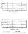
- the composite material forming suppression covering 16b of Figure 5A as a result of this process has the resultant values of permittivity and permeability shown in Figure 7A, these coming about as a result of combining electrical and magnetic properties of the two kinds of particulates described, A and B, with the binding material described distributing them in that binding or host material to form this composite material.
- These properties shown in Figure 7A can be predicted, as indicated above, from the properties shown in Figures 6A and 6B for the two kinds of particulates distributed in the composite material, and from the permittivity characteristics of the binding or host material using the appropriate methods indicated above.
- Particulate A however, has too high a permittivity real part which would result in too much reflection at the outer surface of suppression covering 16 and so too little transmission in the covering.
- Particulate B on the other hand, has too small a permittivity real part and would provide too much transmission.
- Figure 7A an intermediate value is achieved in the two particulate composite material used for suppression covering 16.
- FIG. 7B The result of using this two-particulate composite material to screen the selected metallic rod of 10.0 mm diameter is shown in Figure 7B.
- the graph of Figure 7B shows the reflection of electromagnetic radiation impinging on the rod screened with the composite material described above with respect to the reflection from that same rod in the absence of the composite material screening.
- the reflection at about 10.0 GHz is reduced or suppressed by more than 20 db, almost 30 db, due to the screening by the composite material.
- the volume fraction of the particulates might range from a low of 1% to the loading limit of the binding, or host, material before the ability of the binding material to shrink, for instance, was adversely affected. This might be somewhere between 45% to 70% by volume. Typically, a preferred range for the volume fraction is from 15% to 30%.
- the range might be from a low of .001 microns to a high of several microns. Typically, the range preferred would be from .05 microns to 25 microns.
- binding, or host, material will also have an effect on the electrical properties, but typically not nearly so great as the choice of particulates to be distributed therein.
- the choice of the binding material will also turn on other factors such as the temperature at which the shrinking process or the extruding process can be usefully accomplished, the ability of the material to withstand the environmental conditions in which it will be used so that the suppression covering does not deteriorate or become degraded in its capability, or transmit moisture, etc.
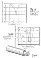
- a further example composite material is provided using a third type of particulate, C, carbonyl iron spheres, type SF, in the same binding material described above in a 30% volume fraction screening the same kind of conductor as before (rod).
- Particulate C is available from GAF under this description. This particulate has the characteristics described in the following table: TABLE III Parameter Particles in Particulate C Hc, Coercivity (Oe) 170 m, Moment (emu/gram) 210 Size, (microns) 1.3 Shape Spherical Aspect ratio 1
- the resulting composite material has the permittivity and permeability characteristics shown in Figure 8A.
- the reflection suppression or attenuation result is shown in Figure 8B.
- the peak suppression has been shifted to around 14.0 GHz and its attenuation reduced to a little more than 15 db.
- the thickness of the suppression covering wall is 1.65 mm.
- the ability to predict the performance of, and to choose from a wide variety of properties of, particulates is especially useful in connection with setting the in which a suppression covering will act to suppress radiation impinging on a structure screened by such a composite material.
- a suppression covering will act to suppress radiation impinging on a structure screened by such a composite material.
- the frequency dependence of the permittivity and permeability of the composite material will have a direct influence on the bandwidth over which such suppression occurs. This frequency dependence of these parameters in the composite material, of course, must result from the frequency dependence of the permittivity and permeability properties of the binding or host matrix and the particulates distributed therein.
- the thickness of the suppression covering around a structure screened thereby was determined to be where the wavelength of the radiation in the suppression covering has been substituted for by the wavelength of this radiation as it comes from the source, that is, the radiation impinging on the covering times the factor indicating the effect on this source wavelength because of the source radiation entering in the material where it has a different wavelength due to the material permittivity and permeability properties.
- the wavelength in a vacuum or near vacuum is equal to the speed of travel of the wave in that medium c divided by its angular frequency or by 2 ⁇ times the event frequency or Substituting this last equation into the preceding equation provides the result which can be rewritten as follows:
- This expression shows which of the frequencies in the impinging radiation will be subject to interference for a given thickness of the suppression covering having a permittivity and a permeability ⁇ .
- the suppression of reflected radiation occurs over a much wider range of frequencies for the curve Wb than for the curve Nb.
- the variation in composite material permittivity and permeability is selected to keep a quarter of the wavelengths of the radiation in the composite material, corresponding to the range of frequencies of interest in the impinging radiation, approximately equal to the thickness of the composite material serving as a suppression covering.
- the factor ( ⁇ ) 1/2 must decrease with increases in the frequency ⁇ .
- the value of the permittivity or the permeability or both must decrease with frequency if this condition is to be met, the frequency value of this decrease settling the low frequency end of the suppression frequency band.
- the ability to put in more than one kind of particulate in the binding or host material allows substantial freedom in adjusting this bandwidth and the point at which the suppression begins along the frequency axis and at which the suppression ends.
- a series of kinds of particulates can be provided in a composite material, each of which has the permittivity or permeability thereof both with a magnitude that decreases with frequency over a range of frequencies differing from the others with successive such ranges overlapping the preceding one. There will result a substantial frequency range in which reflections are suppressed of impinging radiation on a screened structure screened by such a composite material containing this series of particulates.
- FIG. 11 is an end portion of a laminate structure for a suppression covering, 16f, in which the several lamina shown about an end portion of conductor 11 are each of a binding or host material and each contain one or more particulates. If the magnitude decrease with frequency range of interest for the particulates in each lamina are spread out across the suppression frequency range of interest in the fashion shown in Figure 11, the result will be that reflections can be suppressed in different parts of this frequency range of interest by a corresponding lamina.
- a possible arrangement of the structure of Figure 11 would be to provide a series of particulate distributions along a radius of the screened structure with different parameters in each such that the permittivity or permeability or both is increasing in each layer moving inward along that radius.
- These changing parameters in each layer are in effect changing the index of refraction along a radius from the center of the rod.
- Increasing the number of lamina in this arrangement in effect provides a result approaching that of a single suppression covering lamina having a graded index of refraction along a radius.
- particle parameters in such a single lamina can be changed along a radius to provide the result given by laminar suppression covering 16f in Figure 11.
- Particularly beneficial would be to have the initial permittivity and permeability parameters at the outer surface of the suppression covering be near those of a vacuum or air so as to minimize the reflection from this outer surface of the suppression covering.
Landscapes
- Engineering & Computer Science (AREA)
- Microelectronics & Electronic Packaging (AREA)
- Physics & Mathematics (AREA)
- Electromagnetism (AREA)
- Shielding Devices Or Components To Electric Or Magnetic Fields (AREA)
- Laminated Bodies (AREA)
- Insulated Conductors (AREA)
- Finger-Pressure Massage (AREA)
Applications Claiming Priority (2)
| Application Number | Priority Date | Filing Date | Title |
|---|---|---|---|
| US125597 | 1987-11-25 | ||
| US07/125,597 US4814546A (en) | 1987-11-25 | 1987-11-25 | Electromagnetic radiation suppression cover |
Publications (2)
| Publication Number | Publication Date |
|---|---|
| EP0318269A2 true EP0318269A2 (fr) | 1989-05-31 |
| EP0318269A3 EP0318269A3 (fr) | 1990-01-10 |
Family
ID=22420488
Family Applications (1)
| Application Number | Title | Priority Date | Filing Date |
|---|---|---|---|
| EP88311088A Withdrawn EP0318269A3 (fr) | 1987-11-25 | 1988-11-23 | Revêtement supprimant une radiation électromagnétique |
Country Status (6)
| Country | Link |
|---|---|
| US (1) | US4814546A (fr) |
| EP (1) | EP0318269A3 (fr) |
| JP (1) | JPH01189200A (fr) |
| KR (1) | KR890009239A (fr) |
| AU (1) | AU612426B2 (fr) |
| CA (1) | CA1301902C (fr) |
Cited By (1)
| Publication number | Priority date | Publication date | Assignee | Title |
|---|---|---|---|---|
| WO2009024759A3 (fr) * | 2007-08-23 | 2009-04-16 | Qinetiq Ltd | Matériau composite |
Families Citing this family (53)
| Publication number | Priority date | Publication date | Assignee | Title |
|---|---|---|---|---|
| US5106437A (en) * | 1987-11-25 | 1992-04-21 | Minnesota Mining And Manufacturing Company | Electromagnetic radiation suppression cover |
| DE3743320A1 (de) * | 1987-12-21 | 1989-06-29 | Hoechst Ag | 1-olefinstereoblockpolymerwachs und verfahren zu seiner herstellung |
| JPH01292792A (ja) * | 1988-05-18 | 1989-11-27 | Mitsubishi Mining & Cement Co Ltd | 電子装置 |
| US5319173A (en) * | 1988-09-09 | 1994-06-07 | Metcal, Inc. | Temperature auto-regulating, self-heating recoverable articles |
| US5208443A (en) * | 1988-09-09 | 1993-05-04 | Metcal, Inc. | Temperature auto-regulating, self-heating recoverable articles |
| US5085931A (en) * | 1989-01-26 | 1992-02-04 | Minnesota Mining And Manufacturing Company | Microwave absorber employing acicular magnetic metallic filaments |
| US5275880A (en) * | 1989-05-17 | 1994-01-04 | Minnesota Mining And Manufacturing Company | Microwave absorber for direct surface application |
| US5189078A (en) * | 1989-10-18 | 1993-02-23 | Minnesota Mining And Manufacturing Company | Microwave radiation absorbing adhesive |
| US5238975A (en) * | 1989-10-18 | 1993-08-24 | Minnesota Mining And Manufacturing Company | Microwave radiation absorbing adhesive |
| DE69020301T2 (de) * | 1989-10-26 | 1996-02-08 | Colebrand Ltd | Absorber. |
| US5079037A (en) * | 1989-12-28 | 1992-01-07 | Xerox Corporation | Resistive films comprising resistive short fibers in insulating film forming binder |
| US5128504A (en) * | 1990-04-20 | 1992-07-07 | Metcal, Inc. | Removable heating article for use in alternating magnetic field |
| US5182427A (en) * | 1990-09-20 | 1993-01-26 | Metcal, Inc. | Self-regulating heater utilizing ferrite-type body |
| US5389434A (en) * | 1990-10-02 | 1995-02-14 | Minnesota Mining And Manufacturing Company | Electromagnetic radiation absorbing material employing doubly layered particles |
| KR930011548B1 (ko) * | 1991-08-13 | 1993-12-10 | 한국과학기술연구원 | 적층형 전파흡수체 |
| US5278377A (en) * | 1991-11-27 | 1994-01-11 | Minnesota Mining And Manufacturing Company | Electromagnetic radiation susceptor material employing ferromagnetic amorphous alloy particles |
| US6972097B2 (en) * | 1995-07-20 | 2005-12-06 | Nec Tokin Corporation | Composite magnetic material and electromagnetic interference suppressor member using the same |
| CN1158674C (zh) * | 1996-08-26 | 2004-07-21 | Nec东金株式会社 | 复合磁性材料管和其制造方法及电磁干扰抑制管 |
| US6027075A (en) * | 1997-06-16 | 2000-02-22 | Trustees Of Dartmouth College | Systems and methods for modifying ice adhesion strength |
| US7164100B2 (en) * | 1998-06-15 | 2007-01-16 | The Trustees Of Dartmouth College | High-frequency de-icing of cableways |
| US7087876B2 (en) * | 1998-06-15 | 2006-08-08 | The Trustees Of Dartmouth College | High-frequency melting of interfacial ice |
| US20080223842A1 (en) * | 2002-02-11 | 2008-09-18 | The Trustees Of Dartmouth College | Systems And Methods For Windshield Deicing |
| US20090235681A1 (en) * | 2002-02-11 | 2009-09-24 | The Trustees Of Dartmouth College | Pulse Electrothermal Mold Release Icemaker For Refrigerator Having Interlock Closure And Baffle For Safety |
| US7638735B2 (en) * | 2002-02-11 | 2009-12-29 | The Trustees Of Dartmouth College | Pulse electrothermal and heat-storage ice detachment apparatus and methods |
| US20080196429A1 (en) * | 2002-02-11 | 2008-08-21 | The Trustees Of Dartmouth College | Pulse Electrothermal And Heat-Storage Ice Detachment Apparatus And Method |
| US8405002B2 (en) * | 2002-02-11 | 2013-03-26 | The Trustees Of Dartmouth College | Pulse electrothermal mold release icemaker with safety baffles for refrigerator |
| AU2003213017A1 (en) * | 2002-02-11 | 2003-09-04 | The Trustees Of Dartmouth College | Systems and methods for modifying an ice-to-object interface |
| US6909049B2 (en) * | 2002-05-03 | 2005-06-21 | Fci Americas Technologies, Inc. | Electrical connector for angled conductors |
| US6916984B2 (en) * | 2003-07-29 | 2005-07-12 | Pon-Wei Hou | Shielding coating for preventing from outleakage of electromagnetic wave |
| US20050183871A1 (en) * | 2003-07-29 | 2005-08-25 | Pon-Wei Hou | Shielding material for preventing from outleakage and penetration of electromagnetic waves |
| US7703300B2 (en) * | 2004-06-22 | 2010-04-27 | The Trustees Of Dartmouth College | Pulse systems and methods for detaching ice |
| JP2008505459A (ja) * | 2004-07-02 | 2008-02-21 | フェデラル−モーグル コーポレイション | グラフト化コーティング付き点火線およびその製造方法 |
| US7550679B1 (en) * | 2004-11-30 | 2009-06-23 | Mark Wershoven | Active electromagnetic filter |
| EP1866202B1 (fr) * | 2005-04-04 | 2012-11-21 | Goodrich Corporation | Degivreur electrothermique et conducteur de resistance double fonction a utiliser dans cet appareil |
| JP3972951B2 (ja) * | 2005-07-04 | 2007-09-05 | オムロン株式会社 | スイッチング電源、電源装置および電子機器 |
| EP2032916A2 (fr) * | 2006-05-22 | 2009-03-11 | The Trustees of Dartmouth College | Dégivrage électrothermique par impulsions de formes complexes |
| US20080011510A1 (en) * | 2006-07-12 | 2008-01-17 | General Electric Company | Hybrid faceplate having reduced EMI emissions |
| US7781674B2 (en) * | 2006-11-28 | 2010-08-24 | Dorothy Kassab | Protective housing for wires |
| JP5088813B2 (ja) * | 2007-01-23 | 2012-12-05 | 国立大学法人東北大学 | 複合磁性体、その製造方法、それを用いた回路基板、及びそれを用いた電子機器 |
| KR20090103951A (ko) * | 2007-01-23 | 2009-10-01 | 고쿠리츠 다이가쿠 호진 도호쿠 다이가쿠 | 복합 자성체, 그 제조 방법, 그것을 사용한 회로 기판, 및 그것을 사용한 전자 기기 |
| US7511653B2 (en) * | 2007-07-20 | 2009-03-31 | Chang-Sui Yu | Radar wave camouflage structure and method for fabricating the same |
| KR20110103947A (ko) | 2008-11-05 | 2011-09-21 | 더 트러스티즈 오브 다트마우스 칼리지 | 진동―전열 제상부를 구비한 냉매 증발기 |
| JP4523063B1 (ja) * | 2009-03-30 | 2010-08-11 | エンパイア テクノロジー ディベロップメント エルエルシー | 磁性複合体及びその製造方法並びにシールド構造体 |
| US8931296B2 (en) * | 2009-11-23 | 2015-01-13 | John S. Chen | System and method for energy-saving inductive heating of evaporators and other heat-exchangers |
| US8643530B2 (en) * | 2010-01-05 | 2014-02-04 | The United States Of America, As Represented By The Secretary Of The Navy | Apparatus for radar target cloaking using polyhedral conducting mesh |
| CN102893715B (zh) * | 2010-05-10 | 2015-07-01 | 韩国机械研究院 | 宽频电磁波吸收体及其制造方法 |
| US8691393B2 (en) * | 2010-10-27 | 2014-04-08 | Laird Technologies, Inc. | EMI shielding heat shrinkable tapes |
| US20130222171A1 (en) * | 2012-01-12 | 2013-08-29 | Booz, Allen & Hamilton | Radio-frequency (rf) precision nulling device |
| US9845406B2 (en) * | 2013-05-09 | 2017-12-19 | Terry Cassaday | Method and composition re polyurethane seating |
| US9876342B2 (en) | 2013-09-25 | 2018-01-23 | 3M Innovative Properties Company | Compositions for electric field grading |
| DE102014104091A1 (de) * | 2014-03-25 | 2015-10-01 | Fujitsu Technology Solutions Intellectual Property Gmbh | Kabelummantelung für ein Datenkabel eines Computersystems |
| US11492510B2 (en) | 2017-06-16 | 2022-11-08 | Ergocentric Inc. | Protective graft coating for application onto polyurethane for chemical resistance, stain resistance, abrasion resistance and U.V. resistance |
| DE102018100302A1 (de) * | 2018-01-09 | 2019-07-11 | Wobben Properties Gmbh | Windenergieanlagen-Rotorblatt |
Family Cites Families (33)
| Publication number | Priority date | Publication date | Assignee | Title |
|---|---|---|---|---|
| US2027962A (en) * | 1933-03-03 | 1936-01-14 | Nat Carbon Co Inc | Production of articles from plastic compositions |
| US2249091A (en) * | 1937-06-15 | 1941-07-15 | Sprague Specialties Co | Process for the manufacture of electrolytic devices |
| US2863132A (en) * | 1944-10-28 | 1958-12-02 | Amp Inc | Electrical connector with insulated ferrule |
| US3240621A (en) * | 1960-11-14 | 1966-03-15 | Dictaphone Corp | High viscosity dispersions of magnetic pigments |
| US3526896A (en) * | 1961-02-02 | 1970-09-01 | Ludwig Wesch | Resonance absorber for electromagnetic waves |
| US3191132A (en) * | 1961-12-04 | 1965-06-22 | Mayer Ferdy | Electric cable utilizing lossy material to absorb high frequency waves |
| US3938152A (en) * | 1963-06-03 | 1976-02-10 | Mcdonnell Douglas Corporation | Magnetic absorbers |
| US3754255A (en) * | 1971-04-05 | 1973-08-21 | Tokyo Inst Tech | Wide band flexible wave absorber |
| US3843593A (en) * | 1972-06-05 | 1974-10-22 | Du Pont | Radar absorptive coating composition of an acrylic polymer,a polyester and an isocyanate cross-linking agent |
| US3908267A (en) * | 1972-08-23 | 1975-09-30 | Stone Ind Corp | Method of applying an insulating connector |
| GB1433129A (en) * | 1972-09-01 | 1976-04-22 | Raychem Ltd | Materials having non-linear resistance characteristics |
| JPS5418755B2 (fr) * | 1973-03-07 | 1979-07-10 | ||
| US4016356A (en) * | 1973-09-10 | 1977-04-05 | Raychem Limited | Heat recoverable article |
| US4101699A (en) * | 1973-11-23 | 1978-07-18 | Samuel Moore & Company | Synthetic resinous tube |
| JPS50155999A (fr) * | 1974-06-05 | 1975-12-16 | ||
| US4421582A (en) * | 1975-08-04 | 1983-12-20 | Raychem Corporation | Self-heating article with deformable electrodes |
| JPS51163498U (fr) * | 1976-06-09 | 1976-12-27 | ||
| US4137342A (en) * | 1976-10-29 | 1979-01-30 | Minnesota Mining And Manufacturing Company | Cobalt-doped acicular hyper-magnetite particles |
| US4163117A (en) * | 1978-04-19 | 1979-07-31 | Raychem Corporation | Heat-recoverable articles and their use |
| US4319074A (en) * | 1978-08-15 | 1982-03-09 | Trw Inc. | Void-free electrical conductor for power cables and process for making same |
| US4226909A (en) * | 1978-08-21 | 1980-10-07 | Minnesota Mining And Manufacturing Company | Cobalt-doped acicular hyper-magnetite particles |
| US4251304A (en) * | 1979-04-19 | 1981-02-17 | Raychem Corporation | Heat-recoverable articles and their use |
| US4363842A (en) * | 1981-03-02 | 1982-12-14 | Minnesota Mining And Manufacturing Company | Elastomeric pre-stretched tubes for providing electrical stress control |
| US4486721A (en) * | 1981-12-07 | 1984-12-04 | Raychem Corporation | High frequency attenuation core and cable |
| US4499438A (en) * | 1981-12-07 | 1985-02-12 | Raychem Corporation | High frequency attenuation core and cable |
| US4414339A (en) * | 1982-03-15 | 1983-11-08 | The Dow Chemical Company | Low density, electromagnetic radiation absorption composition |
| US4538151A (en) * | 1982-03-31 | 1985-08-27 | Nippon Electric Co., Ltd. | Electro-magnetic wave absorbing material |
| JPS59129118A (ja) * | 1983-01-15 | 1984-07-25 | Fujikura Ltd | 熱収縮性プラスチツク成形体 |
| US4493912A (en) * | 1983-08-15 | 1985-01-15 | General Electric Company | Electromagnetic wave attenuating composition |
| US4624879A (en) * | 1983-11-08 | 1986-11-25 | N.V. Raychem S.A. | Recoverable article |
| US4512833A (en) * | 1983-12-12 | 1985-04-23 | Raychem Corporation | Aluminum-shielded coaxial cable repair |
| JPS60249392A (ja) * | 1984-05-24 | 1985-12-10 | ティーディーケイ株式会社 | 電磁シ−ルド材料 |
| JPH05130262A (ja) * | 1991-11-08 | 1993-05-25 | Seiko Epson Corp | 通信装置 |
-
1987
- 1987-11-25 US US07/125,597 patent/US4814546A/en not_active Expired - Lifetime
-
1988
- 1988-11-14 CA CA000582922A patent/CA1301902C/fr not_active Expired - Lifetime
- 1988-11-15 AU AU25153/88A patent/AU612426B2/en not_active Ceased
- 1988-11-23 EP EP88311088A patent/EP0318269A3/fr not_active Withdrawn
- 1988-11-24 KR KR1019880015496A patent/KR890009239A/ko not_active Ceased
- 1988-11-24 JP JP63297141A patent/JPH01189200A/ja active Pending
Cited By (1)
| Publication number | Priority date | Publication date | Assignee | Title |
|---|---|---|---|---|
| WO2009024759A3 (fr) * | 2007-08-23 | 2009-04-16 | Qinetiq Ltd | Matériau composite |
Also Published As
| Publication number | Publication date |
|---|---|
| AU612426B2 (en) | 1991-07-11 |
| US4814546A (en) | 1989-03-21 |
| JPH01189200A (ja) | 1989-07-28 |
| EP0318269A3 (fr) | 1990-01-10 |
| AU2515388A (en) | 1989-05-25 |
| CA1301902C (fr) | 1992-05-26 |
| KR890009239A (ko) | 1989-07-15 |
Similar Documents
| Publication | Publication Date | Title |
|---|---|---|
| US4814546A (en) | Electromagnetic radiation suppression cover | |
| US5247270A (en) | Dual leaky cables | |
| US5260128A (en) | Electromagnetic shielding sheet | |
| KR102147185B1 (ko) | 전자파 흡수 복합 시트 | |
| US4371742A (en) | EMI-Suppression from transmission lines | |
| EP0322128B1 (fr) | Câble rayonnant | |
| US5389434A (en) | Electromagnetic radiation absorbing material employing doubly layered particles | |
| US5278377A (en) | Electromagnetic radiation susceptor material employing ferromagnetic amorphous alloy particles | |
| US3963999A (en) | Ultra-high-frequency leaky coaxial cable | |
| Hatakeyama et al. | Electromagnetic wave absorber using ferrite absorbing material dispersed with short metal fibers | |
| US5171937A (en) | Metal-coated shielding materials and articles fabricated therefrom | |
| Kotsuka | Electromagnetic wave absorbers: detailed theories and applications | |
| EP0090432B2 (fr) | Matériau absorbant les ondes électro-magnétiques | |
| US5262592A (en) | Filter line cable featuring conductive fiber shielding | |
| KR19980703184A (ko) | 전자기력 흡수 합성물 | |
| Evans | Design guidelines for shielding effectiveness, current carrying capability, and the enhancement of conductivity of composite materials | |
| US7420500B2 (en) | Electromagnetic radiation absorber | |
| EP0516661A1 (fr) | Systeme de localisation a ligne de transmission ouverte. | |
| US4760362A (en) | Leaky coaxial cable providing inductive coupling by eliminating radiating gaps, and the method of making same | |
| Boiprav et al. | Charcoal-and foil-containing materials for radio electronic control systems protection from electromagnetic interferences | |
| Matsumoto et al. | Polymer absorbers containing magnetic particles: effect of polymer permittivity on wave absorption in the quasi-microwave band | |
| EP0479438B1 (fr) | Matériau absorbant les ondes électromagnétiques à particules à double enrobage | |
| CA1332185C (fr) | Cables a fuite | |
| Palanisamy et al. | EMI Shielding of the Copper/Nickel-Coated Polyester Nonwoven | |
| CA1334307C (fr) | Blindage contre le rayonnnement electromagnetique |
Legal Events
| Date | Code | Title | Description |
|---|---|---|---|
| PUAI | Public reference made under article 153(3) epc to a published international application that has entered the european phase |
Free format text: ORIGINAL CODE: 0009012 |
|
| AK | Designated contracting states |
Kind code of ref document: A2 Designated state(s): DE FR GB IT NL |
|
| PUAL | Search report despatched |
Free format text: ORIGINAL CODE: 0009013 |
|
| AK | Designated contracting states |
Kind code of ref document: A3 Designated state(s): DE FR GB IT NL |
|
| 17P | Request for examination filed |
Effective date: 19900709 |
|
| 17Q | First examination report despatched |
Effective date: 19920903 |
|
| STAA | Information on the status of an ep patent application or granted ep patent |
Free format text: STATUS: THE APPLICATION IS DEEMED TO BE WITHDRAWN |
|
| 18D | Application deemed to be withdrawn |
Effective date: 19941101 |