EP0318327A2 - Récipient en métal et sa méthode de fabrication - Google Patents
Récipient en métal et sa méthode de fabrication Download PDFInfo
- Publication number
- EP0318327A2 EP0318327A2 EP88311231A EP88311231A EP0318327A2 EP 0318327 A2 EP0318327 A2 EP 0318327A2 EP 88311231 A EP88311231 A EP 88311231A EP 88311231 A EP88311231 A EP 88311231A EP 0318327 A2 EP0318327 A2 EP 0318327A2
- Authority
- EP
- European Patent Office
- Prior art keywords
- adhesive
- bottom plate
- cylinder
- skirt portion
- joint
- Prior art date
- Legal status (The legal status is an assumption and is not a legal conclusion. Google has not performed a legal analysis and makes no representation as to the accuracy of the status listed.)
- Granted
Links
Images


Classifications
-
- B—PERFORMING OPERATIONS; TRANSPORTING
- B65—CONVEYING; PACKING; STORING; HANDLING THIN OR FILAMENTARY MATERIAL
- B65D—CONTAINERS FOR STORAGE OR TRANSPORT OF ARTICLES OR MATERIALS, e.g. BAGS, BARRELS, BOTTLES, BOXES, CANS, CARTONS, CRATES, DRUMS, JARS, TANKS, HOPPERS, FORWARDING CONTAINERS; ACCESSORIES, CLOSURES, OR FITTINGS THEREFOR; PACKAGING ELEMENTS; PACKAGES
- B65D83/00—Containers or packages with special means for dispensing contents
- B65D83/14—Containers for dispensing liquid or semi-liquid contents by internal gaseous pressure, i.e. aerosol containers comprising propellant
- B65D83/38—Details of the container body
-
- B—PERFORMING OPERATIONS; TRANSPORTING
- B21—MECHANICAL METAL-WORKING WITHOUT ESSENTIALLY REMOVING MATERIAL; PUNCHING METAL
- B21D—WORKING OR PROCESSING OF SHEET METAL OR METAL TUBES, RODS OR PROFILES WITHOUT ESSENTIALLY REMOVING MATERIAL; PUNCHING METAL
- B21D51/00—Making hollow objects
- B21D51/16—Making hollow objects characterised by the use of the objects
- B21D51/26—Making hollow objects characterised by the use of the objects cans or tins; Closing same in a permanent manner
- B21D51/30—Folding the circumferential seam
- B21D51/34—Folding the circumferential seam by pressing
Definitions
- This invention relates to a metal container for pressurised material and to a method of manufacturing the same.
- a container of this type in the prior art, was mainly formed by the step of drawing raw material into a cylindrical body with an integral bottom and processing also the top part to be smaller in diameter for the mouth by so-called necking procedures, whereon the top is closed by another member equipped with valve apparatus in the final stage of the completion.
- the metal container completed through the above procedures in the prior art is restricted in selecting the raw material, like aluminum, since it needs ductility and to be able to be easily cast. Further, the completed container is not strong enough for the pressure endurance because of the nature of the material itself.
- U.S. Patent No. 4,241,844 disclosed the following manufacturing method. Firstly draw the cylindrical body having at its one end the smaller diameter and having its other end open, i.e. with no integral bottom at all, and with the same diameter as the cylindrical body, and then fit a disc-like bottom plate produced by another step in the open end by adhesive joint means and caulking means.
- This method accordingly allows the use of harder metallic material than aluminum, such as steel plate, and thus the cylindrical body is able to be made of steel plate as the said body is produced by means of the step with an open end.
- the adhesive does not almost exist correctly between the whole outer circumference of the bottom plate and the inner wall of the cylinder, and thus the sealing is only kept by the said semilunar-like collective group of the adhesive.
- the effective surface of the adhesive which is to secure the whole outer circumference of the bottom plate with the inner wall becomes quite small, so that the desirable and satisfactory seal is not obtained.
- the disclosure indicates the use of strong adhesive of the hardening type, and therefore when the adhesive comes to a collective group as mentioned aforesaid, the flexibility of the adhesive cannot be attained, and the said group is easily detached or broken against the pressure change caused by the inner forces or against the transformation of the bottom plate or that of the cylinder lower portion caused by the impact load, whereon the sealing is sometimes broken.
- the present invention has as an object the provision of a metal container and a method of manufacturing the same with a satisfactory seal between the cylinder and the bottom plate.
- This invention relates to a metal container and a method of manufacturing the same, wherein a separate bottom plate is fitted in the cylindrical body by adhesive joint means, and it is characterised in increasing the effective areas for adhesive between the inner wall of the cylindrical body and the outer wall of the bottom plate, improving the seal of the adhesive joint means by preventing the hardening adhesive from coming into a semilunar-like collective group, and precluding damage to the sealing part and deterioration of the sealing power caused by the pressure change or the impact load.
- a high-viscose adhesive is utilized, it is adapted to make the relative adhesive coming into the whole gaps correctly so as to increase the sealing ability, whereas both damage and deterioration of the sealing joint part is prevented against the pressure change and the impact load.
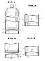
- Figures 1 and 2 show the construction and manufacture of a prior art metal container.
- the present invention is substantially based on the said construction, but it increases the adhesive effect between a cylinder 1 and a bottom plate 2 as well as improving the sealing ability thereof.
- the cylinder 1 has its lower end open and its other end drawn into a smaller diameter top, where a dispensing means 24 such as a cap with an emitting valve is provided, the body between the ends being cylindrical.
- the bottom plate 2 is inserted into the said open end of the cylinder 1 to form the lower closure of the cylinder 1, and it is in the form of a disc with a dome-like top portion 22 and a depending skirt portion 21.
- Adhesive 3 is applied between the fringe of the bottom plate and the inner wall of the cylinder 1 and the sealing joint part is formed between the two components.
- the lowest part of the cylinder 1 is subject to a curling operation and this folds over the skirt portion 21 of the bottom plate 2, whereon the skirt portion is pinched by the lowermost portion of the cylinder, to produce resistance against movement of bottom plate 2 out of the cylinder 1 as a result of inner pressure.
- the adhesive applied between the cylinder 1 and the bottom plate 2 tends to come a semilunar-like collective group between the shoulder of the bottom plate 2 and the inner wall of the cylinder 1 as a result of the frictional engagement of the bottom plate 2 with the inner cylindrical wall during the insertion procedure.
- This invention aims to resolve these problems as mentioned above.
- the cylinder 1 and the bottom plate 2 are the same as those of the prior art, and in the adhesive application step the adhesive is supplied circumferentially along the inner wall of the open end 11 of the cylinder 1.
- a nozzle N of an adhesive container is placed at a defined portion of the inner wall of the cylinder 1 and runs at 150 rpm, for example, and the adhesive agent is, for example, dispersed at 18 c.c. per minute, the adhesive 3 being applied circumferentially along the inner wall of the open end 11 as shown in Figure 3.
- the adhesive applied area must be the contacting area between the skirt portion 21 and the inner wall of the cylinder 1 when the bottom plate is fitted in the cylinder 1.
- the bottom plate 2 is inserted into the cylinder body furnished with adhesive from the open end 11, and as shown in Figure 4, the bottom end of the skirt portion 21 and the open end 11 of the cylinder 1 become axially aligned, i.e. flush.
- the adhesive 3 as shown in Figure 4 comes a semilunar-like group around the periphery of the dome-like portion 22 of the bottom plate 2.
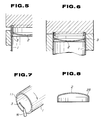
- the assembled body of the said cylinder 1 and the said bottom plate 2 is then placed upside down, and subject to a curling procedure as shown in Figures 5 and 6.
- the curling method is similar to the prior art method, and during the curling step, the bottom plate 2 is forcibly pushed inwardly into the cylinder 1 as the open end portion 11 is bent to interfold the bottom plate 2.
- the curling portion is formed circumferentially all around the bottom end of the skirt portion 21 as shown in Figure 6, and finally the said skirt portion 21 is pinched by the curling portions.
- the following materials are available for forming the cylinder 1: steel plate, steel plate furnished with aluminium plating, aluminium sheet, cladding steel plate and compound steel plate furnished with plastics coating in its inside.
- epoxy solvent agent such as epoxy-amine type, or epoxy-urethane adhesive with high-viscose quality.
- the upper end of the skirt portion 21 can be provided with some taper, but this end can alternatively be without any taper, as shown in Figure 8, having the hemispherical part 23, which is also easy and smooth to allow the said bottom plate 2 to be fitted into the cylinder 1.
- the gap tolerance between the bottom end 11 of the cylinder and the skirt portion 21 is preferably between 0.1 and 0.3mm.
- the skirt portion is equipped with taper, as shown in Figure 4, some small circumferential gaps are formed, into which the adhesive 3 flows. In other words, at least, on the upper part of the skirt portion, adhesive is accordingly provided.
- the cylinder 1 is kept standing upside down, and the caulking is performed on the skirt portion 21.
- the adhesive 3 runs down along the inner wall of the cylinder 1 from its semilunar-like group, and accordingly the said group of the adhesive 3 is gradually running lower and finally it changes its form into a convex style from its original concave style. Keeping this arrangement, the adhesive joint part is dried and the resultant cylinder 1 is surely jointed around the hemisphere of the bottom plate 2.
- the adhesive is now applied over the circumferential edge part of the dome portion 22 and over the inner wall of the cylinder 1 in even thickness, as seen in the convex style between the bottom plate 2 and the cylinder 1. Therefore, the adhesive applied areas can transform themselves in correspondence with the transformation of the dome portion 22 and the inner wall of the cylinder 1.
- the adhesive applied areas can transform themselves accordingly by which the damage by pressure change or impact load is avoided and the satisfactory sealing is kept correct.
- the increase of the effective areas for the adhesive also promotes the sealing ability when compared with the same produced by the prior art.
- test container was of the following construction: Diameter : 50mm Height : 124mm Thickness of the cylindrical body at the joint part: 0.27mm Thickness of the bottom part at the joint part: 0.36mm Material : aluminum alloy Adhesive : Epoxy polyamide plastics adhesive 0.6 gram used.
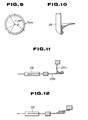
- test specimen was adapted, as shown in Figure 9, cutting the piece down at 5mm wide at 120 degree intervals, and the specimen was completed in the manner of Figure 10.
- the stripping power for the present invention shows 14.0 kgs at maximum and 12.7 kgs at minimum, and 13.34 kgs at average, while the same power against the prior art shows 4.5 kgs at maximum and 2.8 kgs at minimum, and 3.66 kgs at average, all of which show that the strength of a container joint of this invention is approximately 3.5 times that of the prior art.
- the recommendable adhesive is epoxy type, non-solvent, two-part adhesive, and hardening type such as epoxy-amine adhesive, epoxy-polyurethane adhesive and epoxy-polyamide adhesive.
- the adhesive used in the above field test is epoxy-polyamide type in the following constitutions: MAIN AGENT HARDENING AGENT EPOXY QUANTITY 165 ⁇ 185 - AMINE VALUE - 400 ⁇ 440 VISCOSITY 5000 ⁇ 7000 CPS 4000 ⁇ 5000 CPS PERCENTAGE 75% 25%
- the semilunar-like collective group of adhesive is now prevailing over the inner wall of the cylinder 1 and also over the dome portion 22 of the bottom plate 2, and finally the semilunar-like group is formed into a convex shape by distribution of its adhesive.
- the applied adhesive is urethane type belonging to the epoxy-amine system. If the pressure increasing step is effected independently, the pressure condition applied can be a few atmospheric pressures for a few seconds. The above condition depends upon the size of the gap between the cylinder 1 and the skirt portion 21 of the bottom plate 2 and also upon the viscosity of the applied adhesive. In a case where the gap is larger and the viscosity is weaker, the pressurising time must be shortened accordingly, while in a case where the gap is smaller and the viscosity is stronger, the time must be increased.
- the semilunar-like collective group of the adhesive is forced to flow forcibly into the gap between the open end 11 and the skirt portion 21, and the gap is filled with the adhesive as the result.
- the adhesive stays as it is in the gap.
- the pressure step is an independent step as above mentioned, but this relative step proceeds simultaneously in correspondence with the curling step.
- the inside of the cylinder 1 is receiving the fixed pressure, and the adhesive 3 is thus forced to flow into the gap between the cylinder 1 and the skirt portion 21.
- the bottom plate 2 is pushed into the inside of the cylinder by the curling step.
- the adhesive 3 is compelled to flow into the said gap even if the pressure time is quite short.
- the adhesive 3 is also pushed into the gap between the cylinder 1 and the skirt portion 21, whereas the semilunar-like collective group of the adhesive on the upper part of the skirt portion 21 is gradually broken down to move into the gap.
- the following material is available for the cylinder: steel plate, steel plate furnished with aluminum plating, aluminum sheet, thin cladding steel plate and compound steel plate furnished with plastics coating in its inside.
- the applicable adhesive epoxy type, two-part adhesive such as epoxy-amine agent, epoxy-urethane agent and so on, with a quality of strong viscosity.
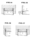
- the bottom plate 2 After the step of putting adhesive on the inner wall of the cylinder 1, the bottom plate 2 is inserted from the open end 11 of the cylinder 1, and at this instant the adhesive 3 forms the semilunar-like group at the upper part of the skirt portion 21. Then the fixed pressure is put into the inside of the cylinder 1, and the semilunar-like group of the adhesive 3 is forced to flow into the said joint section. In other words, the gap is filled with the adhesive. According to the flow of the adhesive 3 as above, the semilunar-like group is gradually broken down into a formation of convex type, contrary to the semilunar-like form.
- the adhesive flows over along the inner wall of the cylinder 1 and also over along the inclined surface of the skirt portion 22 into the average thickness, whereas the adhesive supplied areas are easy to transform in accordance with the transformation of the wall or that of the skirt portion 21.
- the adhesive 3 in those areas stays as it is.
- the adhesive 3 is dried and hardened to connect tightly the joint section between the cylinder 1 and the bottom plate 2.
- the adhesive 3 flows forcibly into the gap between the cylinder 1 and the skirt portion 21, and the said gap is filled with the adhesive 3. Accordingly, the adhesive prevailed areas may transform by themselves in correspondence with the transformation of the inner surface of the skirt portion 21 and also with that of the cylinder inner wall, whereas the sealing joint section is neither damaged by an interior pressure change or by an impact load nor the sealing ability is deteriorated.
- the contacting surface between the inner wall of the cylinder 1 and the skirt portion 21 is larger in comparison with that of the prior art, and therefore the sealing ability is much greater.
- the assembled body of the cylinder 1 and the bottom plate 2 is upright, whereon heating is temporarily employed upon the adhesive joint section.
- the applied adhesive is urethane type belonging to the epoxy-amine system, and the heating condition is defined at 150°C for a few seconds.
- the semilunar-like group of the adhesive 3 at the upper part of the skirt portion 21 gradually runs down into the gap between the open end 11 and the skirt portion 21 because the viscosity is weakened by the heating procedure, and finally the gap is filled with the adhesive 3.
- the adhesive regains its original viscosity.
- an infrared heater H is recommended, or else a high-frequency heater is also applicable.
- the open end 11 is bent inwardly in the curling step.
- the curling step is the same as for the prior art.
- the bottom plate 2 is pushed inwardly into the inside of the cylinder 1, and at the final stage of the relative curling step the curling portion is formed to surround the bottom end of the skirt portion 21, wherefore the skirt portion 21 is pinched by the relative curling portions.
- the applicable adhesive is recommended: two-part adhesive of epoxy type such as epoxy-amine adhesive, epoxy-urethane adhesive with the quality of the strong viscosity.
- the heating procedure is expressed as an independent step, but this procedure may be included together with the insertion step of the bottom plate 2.
- this procedure may be included together with the insertion step of the bottom plate 2.
- the adhesive 3 is furnished, where the bottom plate 2 is inserted from the open end 11 of the cylinder 1 the semilunar-like collective group of the adhesive 3 is formed at the upper part of the skirt portion 21.
- the applied adhesive is of strong viscosity, enough volume of the adhesive does not exist in the joint section between the cylinder 1 and the skirt portion 21.
- the semilunar-like collective group of the adhesive 3 flows into the gap of the said joint section and the adhesive 3 fills the said gap.
- the semilunar-like group of the adhesive 3 gradually decreases its group unity to change into the convex style, and the average prevailing areas of the adhesive 3 adjust themselves to transform in correspondence with the transformation of the cylinder inside wall and with that of the skirt portion 21.
- the adhesive 3 recovers its original viscosity after the heating is stopped, and thus the adhesive 3 remains filling the said joint section.
- the bottom plate 2 is tightly fixed at the lower part of the cylinder 1 through the steps of the said curling and caulking.
- the adhesive 3 stays filling the said gap, whereas the group unity of the semilunar-like collective group of the adhesive 3 gradually decreases to change into the convex style and the average prevailing areas of the adhesive 3 adjust themselves to transform in accordance with the transformation of the cylinder inside wall and with that of the skirt portion 21. It is also understood that the sealing joint section is neither damaged by an internal pressure change or by the impact load nor the sealing ability is deteriorated.
- the adhesive effecting areas between the inner wall of the cylinder 1 and the skirt portion 21 are larger in comparison with that of the prior art, and therefore the sealing ability is far greater.
- This embodiment only requires the simple heater apparatus, which does not affect at all the mass production system both costly and systematically.
- Figures 18 and 19 refer to a still further modification of the invention, which can be applied to any of the embodiments already described.
- a recess or ditch 27 or a plurality of recesses or ditches 27 at fixed intervals therearound is established, so that the adhesive can flow into the curling portion 28 and it is dried and hardened.
- the applicable adhesive 3 is two-part and non-solvent epoxy type with 2,500 ⁇ 4,000cp viscosity.
- the adhesive 3 flows into the curling portion 28 through the ditch 27 and also it fills at the same time the gap between the inner wall of the cylinder 1 and the skirt portion 21. Accordingly, it is not necessary to prepare the slope at the upper part of the skirt portion 21 as shown in Figure 4.
- the gap tolerance between the cylinder 1 and the skirt portion 21 may be fixed at zero, namely no tolerance is necessary.
- the adhesive effective areas are increased and the airtightness therewith is also strengthened, wherefore the durability against a shock caused by falling and so on is well maintained.
- the cut edge is completely covered with the adhesive 3, which prevents the relative edge from becoming rusty, and, further, as the curling portion 28 is filled with adhesive 3 it rejects any incoming of water, and this waterproof situation benefits the step of shrink packaging.
- the shrink film is likely to deform itself by absorbing the aqueous vapour caused by remaining water therewith.
- the aerosol container receives the hot water test for leakage after refilling, and during this test it is quite often that the air existing in the gap of the said curling portion 28 comes out to be mistaken as a leakage. This embodiment definitely avoids such a mistake in the relative testing procedure.
Landscapes
- Engineering & Computer Science (AREA)
- Mechanical Engineering (AREA)
- Chemical & Material Sciences (AREA)
- Dispersion Chemistry (AREA)
- Adhesives Or Adhesive Processes (AREA)
- Rigid Containers With Two Or More Constituent Elements (AREA)
- Containers And Packaging Bodies Having A Special Means To Remove Contents (AREA)
Applications Claiming Priority (7)
| Application Number | Priority Date | Filing Date | Title |
|---|---|---|---|
| JP300490/87 | 1987-11-27 | ||
| JP62300490A JPH0734947B2 (ja) | 1987-11-27 | 1987-11-27 | 圧力容器とその製造方法 |
| JP331757/87 | 1987-12-26 | ||
| JP62331757A JPH0667525B2 (ja) | 1987-12-26 | 1987-12-26 | 圧力容器の製造方法 |
| JP331758/87 | 1987-12-26 | ||
| JP62331758A JPH0677781B2 (ja) | 1987-12-26 | 1987-12-26 | 圧力容器の製造方法 |
| CA000596319A CA1329785C (fr) | 1987-11-27 | 1989-04-11 | Recipient metallique et methode de fabrication |
Publications (3)
| Publication Number | Publication Date |
|---|---|
| EP0318327A2 true EP0318327A2 (fr) | 1989-05-31 |
| EP0318327A3 EP0318327A3 (en) | 1990-01-24 |
| EP0318327B1 EP0318327B1 (fr) | 1993-10-06 |
Family
ID=27426654
Family Applications (1)
| Application Number | Title | Priority Date | Filing Date |
|---|---|---|---|
| EP88311231A Expired - Lifetime EP0318327B1 (fr) | 1987-11-27 | 1988-11-28 | Récipient en métal et sa méthode de fabrication |
Country Status (3)
| Country | Link |
|---|---|
| EP (1) | EP0318327B1 (fr) |
| CA (1) | CA1329785C (fr) |
| DE (1) | DE3884762T2 (fr) |
Cited By (2)
| Publication number | Priority date | Publication date | Assignee | Title |
|---|---|---|---|---|
| EP1889673A1 (fr) * | 2006-08-17 | 2008-02-20 | Corus Staal BV | Procédé de fabrication d'un récipient métallique |
| CN111283112A (zh) * | 2020-03-09 | 2020-06-16 | 山东百源燃气科技发展有限公司 | 一种燃气钢瓶底部填充生产线 |
Families Citing this family (1)
| Publication number | Priority date | Publication date | Assignee | Title |
|---|---|---|---|---|
| DE10257009A1 (de) * | 2002-12-06 | 2004-06-17 | Continental Aktiengesellschaft | Mit Extravolumen versehener Luftfederdeckel und Verfahren zu seiner Herstellung |
Family Cites Families (2)
| Publication number | Priority date | Publication date | Assignee | Title |
|---|---|---|---|---|
| CH564166A5 (fr) * | 1973-03-08 | 1975-07-15 | Alusuisse | |
| EP0260084B1 (fr) * | 1986-09-08 | 1992-12-30 | Asia Can Company Limited | Récipient métallique et procédé pour sa fabrication |
-
1988
- 1988-11-28 EP EP88311231A patent/EP0318327B1/fr not_active Expired - Lifetime
- 1988-11-28 DE DE88311231T patent/DE3884762T2/de not_active Expired - Fee Related
-
1989
- 1989-04-11 CA CA000596319A patent/CA1329785C/fr not_active Expired - Fee Related
Cited By (2)
| Publication number | Priority date | Publication date | Assignee | Title |
|---|---|---|---|---|
| EP1889673A1 (fr) * | 2006-08-17 | 2008-02-20 | Corus Staal BV | Procédé de fabrication d'un récipient métallique |
| CN111283112A (zh) * | 2020-03-09 | 2020-06-16 | 山东百源燃气科技发展有限公司 | 一种燃气钢瓶底部填充生产线 |
Also Published As
| Publication number | Publication date |
|---|---|
| EP0318327A3 (en) | 1990-01-24 |
| DE3884762T2 (de) | 1994-02-10 |
| EP0318327B1 (fr) | 1993-10-06 |
| CA1329785C (fr) | 1994-05-24 |
| DE3884762D1 (de) | 1993-11-11 |
Similar Documents
| Publication | Publication Date | Title |
|---|---|---|
| FI76035B (fi) | Anordning foer formning och insaettning av ett internt lock i en behaollare. | |
| US6371338B1 (en) | Valve arrangement for discharging a fluid medium maintained under pressure in a container | |
| CA1316407C (fr) | Procede de fabrication d'un emballage sous pression a double paroi | |
| US3443006A (en) | Method of making gasketed mounting cups for pressurized aerosol containers | |
| US4415387A (en) | Method of forming an annular seam between two container body halves | |
| US5769465A (en) | System for connecting a housing to a tube | |
| CA1270265A (fr) | Methode de fabrication d'elements de flexion de suspensions pneumatiques | |
| EP0318327A2 (fr) | Récipient en métal et sa méthode de fabrication | |
| US5217139A (en) | Dome-shaped pressurized can | |
| CA2212188C (fr) | Ensemble et procede de montage d'une valve pour recipients aerosol | |
| US5052577A (en) | Container assembly | |
| JPH04505905A (ja) | エーロゾル容器ふた用の改良されたガスケット構造 | |
| EP1700354B1 (fr) | Piece de batterie | |
| US4800642A (en) | Method of producing a hydropneumatic accumulator | |
| EP0020099B1 (fr) | Méthode de production d'une boite | |
| US4787202A (en) | Combustion chamber for rocket motor and its assembling method | |
| US20030024954A1 (en) | Gasketed aerosol mounting cup | |
| CA1137897A (fr) | Collage de deux demi-recipients | |
| US4429718A (en) | Pressure resistant accumulator device | |
| GB2064652A (en) | Pressure vessels | |
| CA1148412A (fr) | Dispositif et methode d'assemblage de moities de recipients | |
| EP0019394A1 (fr) | Récipient en deux pièces et procédé pour assembler ces deux moitiés | |
| US4506431A (en) | Method of making pressure resistant accumulator device | |
| JP7721256B2 (ja) | 熱接着を用いて多孔質表面を備えたインプラントを形成する方法 | |
| US6719514B1 (en) | Process for producing a metal can with an insert piece for packaging, for example, a foodstuff, and a can of this nature |
Legal Events
| Date | Code | Title | Description |
|---|---|---|---|
| PUAI | Public reference made under article 153(3) epc to a published international application that has entered the european phase |
Free format text: ORIGINAL CODE: 0009012 |
|
| AK | Designated contracting states |
Kind code of ref document: A2 Designated state(s): DE FR GB IT |
|
| PUAL | Search report despatched |
Free format text: ORIGINAL CODE: 0009013 |
|
| AK | Designated contracting states |
Kind code of ref document: A3 Designated state(s): DE FR GB IT |
|
| 17P | Request for examination filed |
Effective date: 19900614 |
|
| 17Q | First examination report despatched |
Effective date: 19920427 |
|
| GRAA | (expected) grant |
Free format text: ORIGINAL CODE: 0009210 |
|
| AK | Designated contracting states |
Kind code of ref document: B1 Designated state(s): DE FR GB IT |
|
| REF | Corresponds to: |
Ref document number: 3884762 Country of ref document: DE Date of ref document: 19931111 |
|
| ITF | It: translation for a ep patent filed | ||
| ET | Fr: translation filed | ||
| PLBE | No opposition filed within time limit |
Free format text: ORIGINAL CODE: 0009261 |
|
| STAA | Information on the status of an ep patent application or granted ep patent |
Free format text: STATUS: NO OPPOSITION FILED WITHIN TIME LIMIT |
|
| 26N | No opposition filed | ||
| PGFP | Annual fee paid to national office [announced via postgrant information from national office to epo] |
Ref country code: FR Payment date: 20011113 Year of fee payment: 14 |
|
| PGFP | Annual fee paid to national office [announced via postgrant information from national office to epo] |
Ref country code: GB Payment date: 20011128 Year of fee payment: 14 |
|
| PGFP | Annual fee paid to national office [announced via postgrant information from national office to epo] |
Ref country code: DE Payment date: 20011210 Year of fee payment: 14 |
|
| REG | Reference to a national code |
Ref country code: GB Ref legal event code: IF02 |
|
| PG25 | Lapsed in a contracting state [announced via postgrant information from national office to epo] |
Ref country code: GB Free format text: LAPSE BECAUSE OF NON-PAYMENT OF DUE FEES Effective date: 20021128 |
|
| PG25 | Lapsed in a contracting state [announced via postgrant information from national office to epo] |
Ref country code: DE Free format text: LAPSE BECAUSE OF NON-PAYMENT OF DUE FEES Effective date: 20030603 |
|
| GBPC | Gb: european patent ceased through non-payment of renewal fee | ||
| PG25 | Lapsed in a contracting state [announced via postgrant information from national office to epo] |
Ref country code: FR Free format text: LAPSE BECAUSE OF NON-PAYMENT OF DUE FEES Effective date: 20030731 |
|
| REG | Reference to a national code |
Ref country code: FR Ref legal event code: ST |
|
| PG25 | Lapsed in a contracting state [announced via postgrant information from national office to epo] |
Ref country code: IT Free format text: LAPSE BECAUSE OF NON-PAYMENT OF DUE FEES;WARNING: LAPSES OF ITALIAN PATENTS WITH EFFECTIVE DATE BEFORE 2007 MAY HAVE OCCURRED AT ANY TIME BEFORE 2007. THE CORRECT EFFECTIVE DATE MAY BE DIFFERENT FROM THE ONE RECORDED. Effective date: 20051128 |