EP0318605A1 - Dispositif de réglage de la phase dans une machine à alimentation par feuilles - Google Patents
Dispositif de réglage de la phase dans une machine à alimentation par feuilles Download PDFInfo
- Publication number
- EP0318605A1 EP0318605A1 EP87117645A EP87117645A EP0318605A1 EP 0318605 A1 EP0318605 A1 EP 0318605A1 EP 87117645 A EP87117645 A EP 87117645A EP 87117645 A EP87117645 A EP 87117645A EP 0318605 A1 EP0318605 A1 EP 0318605A1
- Authority
- EP
- European Patent Office
- Prior art keywords
- chain
- slide member
- tension
- sprocket
- shaft
- Prior art date
- Legal status (The legal status is an assumption and is not a legal conclusion. Google has not performed a legal analysis and makes no representation as to the accuracy of the status listed.)
- Granted
Links
Images
Classifications
-
- F—MECHANICAL ENGINEERING; LIGHTING; HEATING; WEAPONS; BLASTING
- F16—ENGINEERING ELEMENTS AND UNITS; GENERAL MEASURES FOR PRODUCING AND MAINTAINING EFFECTIVE FUNCTIONING OF MACHINES OR INSTALLATIONS; THERMAL INSULATION IN GENERAL
- F16H—GEARING
- F16H35/00—Gearings or mechanisms with other special functional features
- F16H35/02—Gearings or mechanisms with other special functional features for conveying rotary motion with cyclically varying velocity ratio
-
- B—PERFORMING OPERATIONS; TRANSPORTING
- B41—PRINTING; LINING MACHINES; TYPEWRITERS; STAMPS
- B41F—PRINTING MACHINES OR PRESSES
- B41F13/00—Common details of rotary presses or machines
- B41F13/0008—Driving devices
-
- B—PERFORMING OPERATIONS; TRANSPORTING
- B65—CONVEYING; PACKING; STORING; HANDLING THIN OR FILAMENTARY MATERIAL
- B65H—HANDLING THIN OR FILAMENTARY MATERIAL, e.g. SHEETS, WEBS, CABLES
- B65H5/00—Feeding articles separated from piles; Feeding articles to machines
- B65H5/34—Varying the phase of feed relative to the receiving machine
-
- F—MECHANICAL ENGINEERING; LIGHTING; HEATING; WEAPONS; BLASTING
- F16—ENGINEERING ELEMENTS AND UNITS; GENERAL MEASURES FOR PRODUCING AND MAINTAINING EFFECTIVE FUNCTIONING OF MACHINES OR INSTALLATIONS; THERMAL INSULATION IN GENERAL
- F16H—GEARING
- F16H7/00—Gearings for conveying rotary motion by endless flexible members
-
- Y—GENERAL TAGGING OF NEW TECHNOLOGICAL DEVELOPMENTS; GENERAL TAGGING OF CROSS-SECTIONAL TECHNOLOGIES SPANNING OVER SEVERAL SECTIONS OF THE IPC; TECHNICAL SUBJECTS COVERED BY FORMER USPC CROSS-REFERENCE ART COLLECTIONS [XRACs] AND DIGESTS
- Y10—TECHNICAL SUBJECTS COVERED BY FORMER USPC
- Y10S—TECHNICAL SUBJECTS COVERED BY FORMER USPC CROSS-REFERENCE ART COLLECTIONS [XRACs] AND DIGESTS
- Y10S474/00—Endless belt power transmission systems or components
- Y10S474/90—Phase variator
Definitions
- the present invention relates to a phase adjusting apparatus for adjusting a relative phase between a paper sheet feeder and a printing apparatus in accordance with a paper feed state for the printing press in a sheet-fed printing press.
- paper sheets stacked on a stack board are drawn by suction one by one by a sheet pick-up device, and are fed onto a feedboard through a feeder board. Thereafter, each sheet is gripped and conveyed by grippers of a swing gripper. The sheets are subjected to printing while being gripped and conveyed by grippers of a plate cylinder of the printing apparatus.
- rotation of a motor is transmitted to a printing apparatus, and is then transmitted to the sheet pick-up device of the paper sheet feeder or a paper conveying tape provided on the feeder board through a chain or a line shaft.
- a rotational phase between the paper sheet feeder and the printing apparatus is set at a given value, when the tape is extended or is slid along a paper sheet, the sheet cannot be fed to the printing apparatus at a predetermined timing.
- grippers may fail to grip the sheet or may grip it unsatisfactorily, resulting in printing error or obstructions causing the printing press to be stopped.
- a phase adjusting apparatus cooperating with elongated holes and bolts is provided at any location in a driving system between the printing apparatus and the paper sheet feeder. If an ab normality is found upon observation of the gripping state of the grippers, the sheet feed timing of the paper sheet feeder is speeded up or delayed with respect to the printing apparatus.
- phase adjusting apparatus cannot be operated during operation of a printing press, and adjustment must be performed after the printing press is stopped. Therefore, workability is degraded, and an operator cannot perform any adjustment while observing the gripping state of the grippers. Therefore, in many cases it is impossible to perform one single appropriate adjustment only, and readjustment must be repeated several times. Therefore, an idle time is prolonged, and the number of wasted paper sheets is increased.
- Another phase adjusting apparatus has been suggested which can be adjusted during the operation of the printing press and uses planetary gears in a driving system between the printing apparatus and the paper sheet feeder. However, this apparatus has a complicated structure, and a distance between the shafts of the gears must be changed. Therefore, the backlash of the gears is increased, thus unstabilizing a phase.
- a phase adjusting apparatus for a sheet-fed printing press for adjusting a relative phase in a rotational direction between a paper sheet feeder and a printing apparatus which are coupled through a chain, comprising a frame, a sprocket which is in contact with the chain from the inside towards a tension run of the chain, a slide member, mounted on the frame through rails, for supporting the sprocket through a short shaft such that the slide member is movable along the longitudinal direction corresponding to a direction perpendicular to an extension direction of the tension run of the chain, slide member driving means for moving the slide member in the longitudinal direction, and a tension sprocket supported on the slide member through a short shaft and in contact with the chain from the inside towards a slack run of the chain, the tension sprocket being biased by a spring member so that the chain is tensioned.
- phase adjusting apparatus for a sheet-fed printing press is provided which is free from the influence of a backlash of the gears and can stabilize a phase and cope with the requirement for a wide range of a change in phase.
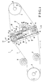
- a driving sprocket 3 is fitted axially, close to a frame 4, on a driving shaft 2 of a printing apparatus and serves as a driving section of a chain driving apparatus 1.
- a driven sprocket 6 is fitted axially, close to the frame 4 on a driving shaft 5 of a paper sheet feeder and serves as a driven section.
- a chain 7 is arranged to form a connection or loop between the driving sprocket 3 and the driven sprocket 5.
- the lower side (Fig. 1) of the chain 7 corresponds to a tension run or side
- the upper side thereof corresponds to a slack run or side.
- Tension sprockets 8 and 9 supported by the frame 4 and fixed to shafts each are in contact, respectively, with the tension and slack run of the chain 7 near the driving sprocket 3.
- a phase adjusting apparatus generally denoted by reference numeral 10 is arranged between the tension sprockets 8 and 9 and the driven sprocket 6. More specifically, a guide rail 11 substantially perpendicular to a line connecting the centres of the shafts 2 and 5, and guide rails 12 and 13 divided in a longitudinal direction and arranged parallel to the rail guide 11 are fixed to the inner surface of the frame 4 by bolts 14.
- Reference numeral 15 denotes a strip slide base used as a slide member which is formed to be movable with respect to the tension and slack runs such that the upper and lower surfaces are slidable along flange portions of the guide rails 11, 12, and 13 and the inner surface of the frame 4.
- a short shaft 16 is fixed to the lower end portion of the slide base 15 by a stop 17.
- a sprocket 18 which is in internal engagement with the tension run of the chain 7 is fitted rotatably on the short shaft 16.
- a thin-walled portion 15a having a thickness approximately half that of the slide base 15, is formed in the upper portion of the slide base 15.
- a rectangular slide block 19 is supported to be movable relative to the tension and slack runs such that its upper and lower surfaces are in slidable contact with the inner surface of the thin-walled portion 15a and the flange surfaces of the slide guides 11 and 12.
- a short shaft 20 is fixed at the central portion in the widthwise direction of the slide block 19 by a stop 21.
- a tension sprocket 22 which is in internal engagement with the slack run of the chain 7 is fitted rotatably on the short shaft 20. Furthermore, a pair of stepped spring holes 19a extend vertically through the slide block 19. Furthermore, spring holes 15b are formed in the slide base 15 so as to correspond to the spring holes 19a. Compression coil springs 24 are interposed between collars of spring shafts 23 inserted in the spring holes 19a and 15a and the bottom surfaces of the spring holes 15b, respectively. The compression coil springs 24 accumulate a biasing force in a direction for separating the slide block 19 from the slide base 15 by adjusting screws 25 threadably engaged in threaded portions of the spring holes 19a.
- the tension sprocket 22 is biased on a direction for tensioning the slack run of the chain 7 by the compression coil springs 24.
- the biasing force can be adjusted by forward or backward movement of each adjusting screw 25.
- Reference numeral 26 denotes a stopper for the slide block 19, which is fixed to the upper end face of the slide base 15 by bolts; and 15c, a sliding grease groove between the slide base 15 and the frame 4.
- Reference numeral 27 generally denotes a driving apparatus for moving the slide base 15 to the slack or tension side.
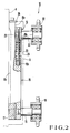
- the driving apparatus 27 comprises a U-shaped bracket 28 fixed outside the frame 4 at a position corresponding to a divided portion between the guide rails 12 and 13.
- An operating shaft 30 carrying a knob 29 parallel to the frame 4 is supported pivotally on the bracket 28.
- a worm 31 is fitted axially on the operating shaft 30.
- a driving shaft 33 having a worm wheel 32 which is meshed with the worm 31 is fitted pivotally on the frame 4.
- a pinion 35 meshed with a rack 34 formed on the slide base 15 is fixed to the other end of the driving shaft 33.
- the operation of the phase adjusting apparatus with the above structure will now be described.
- the driving shaft 2 is driven and rotated by a motor side, so that respective cylinders of the printing apparatus are rotated and grippers are opened/closed.
- the rotation of the driving shaft 2 is transmitted to the driven shaft 5 through the chain 7, and paper suction in the paper sheet feeder, paper conveyance by a conveying tape, and the like are performed.
- Tensile forces by the tension sprockets 8, 9 and 22, and the sprocket 18 act on the chain 7.
- the set screw 36 is loosened, and then, the operator turns the operating shaft 30 while holding the knob 29 during the operation of a printing press. Then, the driving shaft 33 is pivoted through the worm 31 and the worm wheel 32, and the sprocket 19 is moved downward in Fig. 1 together with the slide base 15 through the pinion 35 and the rack 34. In this case, a force for moving the sprocket 18 by the driving apparatus 27 overcomes the biasing force of the compression coil springs 24.
- the length of the tension run of the chain 7 becomes larger than that of the slack run. More specifically, assuming the driving shaft 2 is fixed in position, the driven shaft 5 is slightly pivoted in the direction indicated by arrow B, and the phase of the driven shaft 5 is advanced with respect to the driving shaft 2. Therefore, the phase of the paper sheet feeder is advanced with respect to the printing apparatus, and a paper feed timing for the printing apparatus which has been delayed due to paper slippage can be speeded up or advanced, thus resuming the operation at a normal timing.
- the tension sprockets 8 and 9 are fixed to the shafts, and are simply rotated at identical positions. After phase adjustment, the set screw 36 is tightened so as not to change a phase. The operator can perform the above operation during the operation of the printing press while observing the paper feed state for the printing apparatus.
- the tension sprocket 22 is arranged along a line substantially perpendicular to the chain 7 while it is biased against the sprocket 18 by the compression coil springs 24.
- the tension spring 22 may be arranged independently to be separated from the sprocket 18 and to be located at, for example, a position of the tension sprocket 8.
- a slide member with a sprocket which is in internal contact with a tension run or side of a chain for coupling a paper sheet feeder and a printing apparatus in a sheet-fed printing press.
- the slide member is supported to be movable in a direction substantially perpendicular to an extension direction of the tension side of the chain.
- Operating means are provided to a press frame, and a chain sprocket is arranged which is biased in a tension direction of the chain by a spring member so as to be in contact with the slack run or side of the chain.
Landscapes
- Engineering & Computer Science (AREA)
- Mechanical Engineering (AREA)
- General Engineering & Computer Science (AREA)
- Handling Of Sheets (AREA)
- Supply, Installation And Extraction Of Printed Sheets Or Plates (AREA)
- Rotary Presses (AREA)
Priority Applications (2)
| Application Number | Priority Date | Filing Date | Title |
|---|---|---|---|
| AT87117645T ATE80577T1 (de) | 1987-11-28 | 1987-11-28 | Phaseneinstellvorrichtung fuer eine bogendruckmaschine. |
| DE19873781805 DE3781805T2 (de) | 1987-11-28 | 1987-11-28 | Phaseneinstellvorrichtung fuer eine bogendruckmaschine. |
Applications Claiming Priority (1)
| Application Number | Priority Date | Filing Date | Title |
|---|---|---|---|
| US07/126,278 US4791869A (en) | 1987-11-30 | 1987-11-30 | Phase adjusting apparatus for sheet-fed printing press |
Publications (2)
| Publication Number | Publication Date |
|---|---|
| EP0318605A1 true EP0318605A1 (fr) | 1989-06-07 |
| EP0318605B1 EP0318605B1 (fr) | 1992-09-16 |
Family
ID=22423963
Family Applications (1)
| Application Number | Title | Priority Date | Filing Date |
|---|---|---|---|
| EP87117645A Expired EP0318605B1 (fr) | 1987-11-28 | 1987-11-28 | Dispositif de réglage de la phase dans une machine à alimentation par feuilles |
Country Status (2)
| Country | Link |
|---|---|
| US (1) | US4791869A (fr) |
| EP (1) | EP0318605B1 (fr) |
Cited By (2)
| Publication number | Priority date | Publication date | Assignee | Title |
|---|---|---|---|---|
| FR2649040A1 (fr) * | 1989-07-01 | 1991-01-04 | Heidelberger Druckmasch Ag | Machine d'impression de feuilles comportant un marqueur de feuilles et un mecanisme imprimeur |
| EP1574354A1 (fr) * | 2004-03-10 | 2005-09-14 | Hohner Maschinenbau GmbH | Assembleuse et brocheuse avec deux arbres d'entrainement |
Families Citing this family (14)
| Publication number | Priority date | Publication date | Assignee | Title |
|---|---|---|---|---|
| GB2232456B (en) * | 1989-06-08 | 1993-06-16 | Heidelberger Druckmasch Ag | Drive wheel phase relationship adjustment device |
| DE4028756C1 (fr) * | 1990-09-11 | 1992-03-26 | Heidelberger Druckmaschinen Ag, 6900 Heidelberg, De | |
| DE19625064C2 (de) * | 1996-06-22 | 2002-09-05 | Armin Steuer | Verfahren und Vorrichtung zum Übertragen von Flächenabschnitten von einer Trägerbahn auf ein Flachmaterial |
| NL1006150C2 (nl) * | 1997-05-28 | 1998-12-01 | Stork X Cel Bv | Drukwerkwijze, drukinrichting, alsmede samenstel van drukinrichting en invoereenheid. |
| US6912952B1 (en) | 1998-05-24 | 2005-07-05 | Hewlett-Packard Indigo B.V. | Duplex printing system |
| US6171208B1 (en) * | 1999-01-27 | 2001-01-09 | Pellegrini Meccanica S.P.A. | Device for tensioning flexible elements wound onto pulleys |
| AU1072900A (en) * | 1999-11-07 | 2001-06-06 | Indigo N.V. | Tandem printing system with fine paper-position correction |
| CA2406107A1 (fr) | 2000-04-18 | 2001-10-25 | Indigo N.V. | Position de transport de feuille et ecran de surveillance de blocage |
| DE10157500B4 (de) * | 2000-12-19 | 2015-06-18 | Heidelberger Druckmaschinen Ag | Rotationsdruckmaschine |
| AU2003243568A1 (en) * | 2002-06-17 | 2003-12-31 | Swagelok Company | Ultrasonic testing of fitting assembly for fluid conduits |
| DE10344417B4 (de) * | 2003-01-24 | 2018-06-21 | Heidelberger Druckmaschinen Ag | Bogenanleger mit einem Antrieb zum taktmäßigen Zuführen von Bogen zu einer Bogen verarbeitenden Maschine |
| JP4732697B2 (ja) * | 2003-01-24 | 2011-07-27 | ハイデルベルガー ドルツクマシーネン アクチエンゲゼルシヤフト | 枚葉紙を枚葉紙処理機にタイミング制御して供給する駆動装置を備えた枚葉紙給紙装置 |
| DE202006000966U1 (de) * | 2006-01-20 | 2006-03-30 | Elodrive Gmbh Stellantriebstechnik | Elektromotorischer Stellantrieb |
| US11536350B1 (en) * | 2021-06-28 | 2022-12-27 | Lennox Industries Inc. | Tensioning systems and methods |
Citations (5)
| Publication number | Priority date | Publication date | Assignee | Title |
|---|---|---|---|---|
| DE413494C (de) * | 1922-08-15 | 1925-05-11 | Anglo American Inv S Syndicate | Einstellvorrichtung fuer die Bogenanlegevorrichtung von Druckpressen und anderen bogenverarbeitenden Maschinen |
| US1578329A (en) * | 1922-06-21 | 1926-03-30 | Fuchs & Lang Mfg Company | Feeding mechanism for printing presses |
| US2212348A (en) * | 1937-08-14 | 1940-08-20 | Ball Brothers Co | Drive and timing mechanism |
| GB715732A (en) * | 1951-03-10 | 1954-09-22 | Faber & Schleicher A G | Improvements in or relating to printing machines |
| DE1910733A1 (de) * | 1969-03-03 | 1970-09-17 | Spiess Dr Ing Helmut | Antrieb fuer Bogenanleger |
Family Cites Families (5)
| Publication number | Priority date | Publication date | Assignee | Title |
|---|---|---|---|---|
| US1819743A (en) * | 1931-08-18 | Mechanism for automatically and synchronously adjusting the ignition | ||
| US3166947A (en) * | 1963-04-17 | 1965-01-26 | Robert V Hendershot | Phase variator |
| DE2829026C2 (de) * | 1978-07-01 | 1981-10-08 | Heidelberger Druckmaschinen Ag, 6900 Heidelberg | Vorrichtung zum Antrieb oder zur Synchronisierung von Zylindern in Offsetdruckmaschinen |
| JPS5817089B2 (ja) * | 1978-12-14 | 1983-04-05 | 株式会社椿本チエイン | 原動スプロケツトの軸と従動スプロケツトの軸との相対軸角度の位置合せ装置 |
| JPS58178042A (ja) * | 1982-04-12 | 1983-10-18 | Nagata Seiki Kk | 出力軸回転角自動制御装置 |
-
1987
- 1987-11-28 EP EP87117645A patent/EP0318605B1/fr not_active Expired
- 1987-11-30 US US07/126,278 patent/US4791869A/en not_active Expired - Fee Related
Patent Citations (5)
| Publication number | Priority date | Publication date | Assignee | Title |
|---|---|---|---|---|
| US1578329A (en) * | 1922-06-21 | 1926-03-30 | Fuchs & Lang Mfg Company | Feeding mechanism for printing presses |
| DE413494C (de) * | 1922-08-15 | 1925-05-11 | Anglo American Inv S Syndicate | Einstellvorrichtung fuer die Bogenanlegevorrichtung von Druckpressen und anderen bogenverarbeitenden Maschinen |
| US2212348A (en) * | 1937-08-14 | 1940-08-20 | Ball Brothers Co | Drive and timing mechanism |
| GB715732A (en) * | 1951-03-10 | 1954-09-22 | Faber & Schleicher A G | Improvements in or relating to printing machines |
| DE1910733A1 (de) * | 1969-03-03 | 1970-09-17 | Spiess Dr Ing Helmut | Antrieb fuer Bogenanleger |
Cited By (6)
| Publication number | Priority date | Publication date | Assignee | Title |
|---|---|---|---|---|
| FR2649040A1 (fr) * | 1989-07-01 | 1991-01-04 | Heidelberger Druckmasch Ag | Machine d'impression de feuilles comportant un marqueur de feuilles et un mecanisme imprimeur |
| GB2234961A (en) * | 1989-07-01 | 1991-02-20 | Heidelberger Druckmasch Ag | Sheet feed |
| AU631429B2 (en) * | 1989-07-01 | 1992-11-26 | Heidelberger Druckmaschinen Aktiengesellschaft | Sheet-fed printing press |
| GB2234961B (en) * | 1989-07-01 | 1994-01-26 | Heidelberger Druckmasch Ag | Sheet-fed printing press assembly |
| EP1574354A1 (fr) * | 2004-03-10 | 2005-09-14 | Hohner Maschinenbau GmbH | Assembleuse et brocheuse avec deux arbres d'entrainement |
| US7407461B2 (en) | 2004-03-10 | 2008-08-05 | Hohner Maschinenbau Gmbh | Gatherer stitcher having two operating shafts |
Also Published As
| Publication number | Publication date |
|---|---|
| US4791869A (en) | 1988-12-20 |
| EP0318605B1 (fr) | 1992-09-16 |
Similar Documents
| Publication | Publication Date | Title |
|---|---|---|
| EP0318605A1 (fr) | Dispositif de réglage de la phase dans une machine à alimentation par feuilles | |
| US4754867A (en) | Automated belt drive for PC board feed apparatus | |
| CN1128742C (zh) | 一种用于侧向对正薄片或板状工件的滚轮或皮带校正装置 | |
| US5385342A (en) | Sheet feeder for a sheet-fed printing press and method of feeding sheets therewith | |
| US4038921A (en) | Means to connect printing presses in tandem | |
| JPH1044366A (ja) | 輪転印刷機の排紙装置における自動フォルマート調節装置 | |
| JP2602585B2 (ja) | ワークピース整合装置 | |
| US5429468A (en) | Cover alignment apparatus for book binder | |
| JP2004345727A (ja) | ラベルの貼付装置 | |
| US5170707A (en) | Adjusting device for varying a phase angle between an input shaft and an output shaft of a chain drive in a sheet-fed printing press | |
| CN115504229B (zh) | 一种自动输送装置和自动上料码垛一体机 | |
| JPS6339341A (ja) | 枚葉印刷機の位相調整装置 | |
| US4471695A (en) | Two-sided printing machine | |
| EP0326393B1 (fr) | Mécanisme d'alimentation du papier | |
| JP4003184B2 (ja) | 基板搬送装置 | |
| CN1169370A (zh) | 具有纸张传送带的印刷机 | |
| EP0754549A1 (fr) | Dispositif pour pincer une feuille dans une machine à imprimer | |
| JP2733906B2 (ja) | 製本装置 | |
| JP2564220B2 (ja) | 基板の搬送路変更装置 | |
| CN223303013U (zh) | 斜坡送纸装置及纸包机 | |
| CN220484623U (zh) | 一种烟叶夹爪 | |
| JP2944645B1 (ja) | 薄板の取出し積重ね収納装置 | |
| JP3515258B2 (ja) | つかみ機構駆動装置 | |
| JP2004193182A (ja) | テープ搬送装置 | |
| SU1097496A1 (ru) | Подающее устройство деревообрабатывающего станка |
Legal Events
| Date | Code | Title | Description |
|---|---|---|---|
| PUAI | Public reference made under article 153(3) epc to a published international application that has entered the european phase |
Free format text: ORIGINAL CODE: 0009012 |
|
| 17P | Request for examination filed |
Effective date: 19880413 |
|
| AK | Designated contracting states |
Kind code of ref document: A1 Designated state(s): AT CH DE FR GB IT LI SE |
|
| RAP1 | Party data changed (applicant data changed or rights of an application transferred) |
Owner name: KOMORI CORPORATION |
|
| 17Q | First examination report despatched |
Effective date: 19910320 |
|
| GRAA | (expected) grant |
Free format text: ORIGINAL CODE: 0009210 |
|
| AK | Designated contracting states |
Kind code of ref document: B1 Designated state(s): AT CH DE FR GB IT LI SE |
|
| REF | Corresponds to: |
Ref document number: 80577 Country of ref document: AT Date of ref document: 19921015 Kind code of ref document: T |
|
| ET | Fr: translation filed | ||
| REF | Corresponds to: |
Ref document number: 3781805 Country of ref document: DE Date of ref document: 19921022 |
|
| ITF | It: translation for a ep patent filed | ||
| PLBI | Opposition filed |
Free format text: ORIGINAL CODE: 0009260 |
|
| 26 | Opposition filed |
Opponent name: KBA- PLANETA AG Effective date: 19930521 |
|
| PLBN | Opposition rejected |
Free format text: ORIGINAL CODE: 0009273 |
|
| STAA | Information on the status of an ep patent application or granted ep patent |
Free format text: STATUS: OPPOSITION REJECTED |
|
| 27O | Opposition rejected |
Effective date: 19940428 |
|
| EAL | Se: european patent in force in sweden |
Ref document number: 87117645.9 |
|
| PGFP | Annual fee paid to national office [announced via postgrant information from national office to epo] |
Ref country code: AT Payment date: 19970929 Year of fee payment: 11 |
|
| PGFP | Annual fee paid to national office [announced via postgrant information from national office to epo] |
Ref country code: SE Payment date: 19971009 Year of fee payment: 11 |
|
| PGFP | Annual fee paid to national office [announced via postgrant information from national office to epo] |
Ref country code: GB Payment date: 19971106 Year of fee payment: 11 |
|
| PGFP | Annual fee paid to national office [announced via postgrant information from national office to epo] |
Ref country code: FR Payment date: 19971117 Year of fee payment: 11 |
|
| PGFP | Annual fee paid to national office [announced via postgrant information from national office to epo] |
Ref country code: CH Payment date: 19971128 Year of fee payment: 11 |
|
| PGFP | Annual fee paid to national office [announced via postgrant information from national office to epo] |
Ref country code: DE Payment date: 19980130 Year of fee payment: 11 |
|
| PG25 | Lapsed in a contracting state [announced via postgrant information from national office to epo] |
Ref country code: GB Free format text: LAPSE BECAUSE OF NON-PAYMENT OF DUE FEES Effective date: 19981128 Ref country code: AT Free format text: LAPSE BECAUSE OF NON-PAYMENT OF DUE FEES Effective date: 19981128 |
|
| PG25 | Lapsed in a contracting state [announced via postgrant information from national office to epo] |
Ref country code: SE Free format text: LAPSE BECAUSE OF NON-PAYMENT OF DUE FEES Effective date: 19981129 |
|
| PG25 | Lapsed in a contracting state [announced via postgrant information from national office to epo] |
Ref country code: LI Free format text: LAPSE BECAUSE OF NON-PAYMENT OF DUE FEES Effective date: 19981130 Ref country code: CH Free format text: LAPSE BECAUSE OF NON-PAYMENT OF DUE FEES Effective date: 19981130 |
|
| REG | Reference to a national code |
Ref country code: CH Ref legal event code: PL |
|
| GBPC | Gb: european patent ceased through non-payment of renewal fee |
Effective date: 19981128 |
|
| PG25 | Lapsed in a contracting state [announced via postgrant information from national office to epo] |
Ref country code: FR Free format text: LAPSE BECAUSE OF NON-PAYMENT OF DUE FEES Effective date: 19990730 |
|
| EUG | Se: european patent has lapsed |
Ref document number: 87117645.9 |
|
| REG | Reference to a national code |
Ref country code: FR Ref legal event code: ST |
|
| PG25 | Lapsed in a contracting state [announced via postgrant information from national office to epo] |
Ref country code: DE Free format text: LAPSE BECAUSE OF NON-PAYMENT OF DUE FEES Effective date: 19990901 |
|
| PG25 | Lapsed in a contracting state [announced via postgrant information from national office to epo] |
Ref country code: IT Free format text: LAPSE BECAUSE OF NON-PAYMENT OF DUE FEES;WARNING: LAPSES OF ITALIAN PATENTS WITH EFFECTIVE DATE BEFORE 2007 MAY HAVE OCCURRED AT ANY TIME BEFORE 2007. THE CORRECT EFFECTIVE DATE MAY BE DIFFERENT FROM THE ONE RECORDED. Effective date: 20051128 |