EP0318881A1 - Four de fusion pour la fabrication de bandes sous atmosphère protectrice - Google Patents
Four de fusion pour la fabrication de bandes sous atmosphère protectrice Download PDFInfo
- Publication number
- EP0318881A1 EP0318881A1 EP88119763A EP88119763A EP0318881A1 EP 0318881 A1 EP0318881 A1 EP 0318881A1 EP 88119763 A EP88119763 A EP 88119763A EP 88119763 A EP88119763 A EP 88119763A EP 0318881 A1 EP0318881 A1 EP 0318881A1
- Authority
- EP
- European Patent Office
- Prior art keywords
- continuous casting
- casting mold
- chamber
- melting
- melting furnace
- Prior art date
- Legal status (The legal status is an assumption and is not a legal conclusion. Google has not performed a legal analysis and makes no representation as to the accuracy of the status listed.)
- Granted
Links
- 238000009749 continuous casting Methods 0.000 title claims abstract description 70
- 238000002844 melting Methods 0.000 title claims abstract description 64
- 230000008018 melting Effects 0.000 title claims abstract description 64
- 230000001681 protective effect Effects 0.000 title claims abstract description 6
- 238000004519 manufacturing process Methods 0.000 title description 3
- 239000000155 melt Substances 0.000 claims abstract description 28
- 239000007858 starting material Substances 0.000 claims abstract description 10
- 238000000605 extraction Methods 0.000 claims description 22
- 238000010894 electron beam technology Methods 0.000 claims description 20
- 239000007789 gas Substances 0.000 description 5
- 238000001816 cooling Methods 0.000 description 4
- 238000010438 heat treatment Methods 0.000 description 4
- 238000000034 method Methods 0.000 description 4
- 229910045601 alloy Inorganic materials 0.000 description 2
- 239000000956 alloy Substances 0.000 description 2
- 238000004140 cleaning Methods 0.000 description 2
- 230000007547 defect Effects 0.000 description 2
- 238000001704 evaporation Methods 0.000 description 2
- 230000008020 evaporation Effects 0.000 description 2
- 239000012535 impurity Substances 0.000 description 2
- VYZAMTAEIAYCRO-UHFFFAOYSA-N Chromium Chemical compound [Cr] VYZAMTAEIAYCRO-UHFFFAOYSA-N 0.000 description 1
- 239000000654 additive Substances 0.000 description 1
- 239000012080 ambient air Substances 0.000 description 1
- 230000015572 biosynthetic process Effects 0.000 description 1
- 238000006243 chemical reaction Methods 0.000 description 1
- 229910052804 chromium Inorganic materials 0.000 description 1
- 239000011651 chromium Substances 0.000 description 1
- 238000010276 construction Methods 0.000 description 1
- 230000003111 delayed effect Effects 0.000 description 1
- 238000000151 deposition Methods 0.000 description 1
- 238000007599 discharging Methods 0.000 description 1
- 238000006073 displacement reaction Methods 0.000 description 1
- 238000009826 distribution Methods 0.000 description 1
- 230000000694 effects Effects 0.000 description 1
- 230000005484 gravity Effects 0.000 description 1
- 239000011261 inert gas Substances 0.000 description 1
- 239000007791 liquid phase Substances 0.000 description 1
- 239000000463 material Substances 0.000 description 1
- 238000010309 melting process Methods 0.000 description 1
- 229910052751 metal Inorganic materials 0.000 description 1
- 239000002184 metal Substances 0.000 description 1
- 150000002739 metals Chemical class 0.000 description 1
- 239000000203 mixture Substances 0.000 description 1
- 238000012544 monitoring process Methods 0.000 description 1
- 229910052756 noble gas Inorganic materials 0.000 description 1
- 230000035515 penetration Effects 0.000 description 1
- 239000012071 phase Substances 0.000 description 1
- 230000001105 regulatory effect Effects 0.000 description 1
- 238000003303 reheating Methods 0.000 description 1
- 230000000630 rising effect Effects 0.000 description 1
- 239000002893 slag Substances 0.000 description 1
- 229910000601 superalloy Inorganic materials 0.000 description 1
Images


Classifications
-
- C—CHEMISTRY; METALLURGY
- C22—METALLURGY; FERROUS OR NON-FERROUS ALLOYS; TREATMENT OF ALLOYS OR NON-FERROUS METALS
- C22B—PRODUCTION AND REFINING OF METALS; PRETREATMENT OF RAW MATERIALS
- C22B9/00—General processes of refining or remelting of metals; Apparatus for electroslag or arc remelting of metals
- C22B9/006—General processes of refining or remelting of metals; Apparatus for electroslag or arc remelting of metals with use of an inert protective material including the use of an inert gas
-
- B—PERFORMING OPERATIONS; TRANSPORTING
- B22—CASTING; POWDER METALLURGY
- B22D—CASTING OF METALS; CASTING OF OTHER SUBSTANCES BY THE SAME PROCESSES OR DEVICES
- B22D11/00—Continuous casting of metals, i.e. casting in indefinite lengths
- B22D11/04—Continuous casting of metals, i.e. casting in indefinite lengths into open-ended moulds
- B22D11/0403—Multiple moulds
-
- B—PERFORMING OPERATIONS; TRANSPORTING
- B22—CASTING; POWDER METALLURGY
- B22D—CASTING OF METALS; CASTING OF OTHER SUBSTANCES BY THE SAME PROCESSES OR DEVICES
- B22D11/00—Continuous casting of metals, i.e. casting in indefinite lengths
- B22D11/10—Supplying or treating molten metal
- B22D11/11—Treating the molten metal
-
- B—PERFORMING OPERATIONS; TRANSPORTING
- B22—CASTING; POWDER METALLURGY
- B22D—CASTING OF METALS; CASTING OF OTHER SUBSTANCES BY THE SAME PROCESSES OR DEVICES
- B22D27/00—Treating the metal in the mould while it is molten or ductile ; Pressure or vacuum casting
- B22D27/15—Treating the metal in the mould while it is molten or ductile ; Pressure or vacuum casting by using vacuum
Definitions
- the invention relates to a melting furnace for producing continuous casting blocks in a protective gas atmosphere with a charging device for supplying starting material in a melting area within a melting chamber provided with a chamber bottom, with at least one energy source for melting the starting material, with a continuous casting mold for converting the melt into a block, with an extraction device for the block arranged below the continuous casting mold and with an extraction chamber surrounding the block and the extraction device and associated with the continuous casting mold.
- protective gas atmosphere is understood to mean an atmosphere in which a reaction of the material to be remelted is avoided.
- the protective gas atmosphere can be formed by a corresponding negative pressure (vacuum), inert gas, noble gas or a reducing gas.
- a melting furnace of the type described at the outset is described in the W.C. Heraeus GMbH "Electron Beam Melting Plants N6", 1966, page 62.
- Under the chamber floor there are two withdrawal chambers rotatable in the manner of a revolver with extraction devices which can alternately be coupled with a single continuous casting mold arranged in the chamber floor.
- the upper sides of the discharge chambers and the underside of the continuous casting mold are each provided with a vacuum valve, so that the penetration of ambient air into the melting furnace as well as into the extraction chamber can be prevented after the respective extraction chamber has been separated from the melting chamber.
- the melting chamber is also charged with a new melting electrode using one of the extraction chambers.
- readily volatile metals can evaporate from the standing, molten contents of an intermediate container during the corresponding long break in operation. For example, this reduces the chromium content of a superalloy from 19% to 18%, so that the specification for the alloy in question can no longer be met.
- the invention is therefore based on the object of improving a melting furnace of the type described above in such a way that a quasi-continuous mode of operation is made possible.
- the relative movement between the continuous casting molds and the melting area described in feature a) can be brought about in various ways. On the one hand, it is possible to move or pivot the continuous casting molds one after the other into the falling path of the melt. Furthermore, it is possible to arrange a displaceable melt container or a swivel channel between stationary continuous casting molds and a fixed melting area, and finally it is also possible to spatially shift the melting area and to assign it to the individual continuous casting molds one after the other.
- the duration of the interruption in operation is reduced to approximately 20 seconds, which leads to a loss of time of less than 1% with a melting time of 30 minutes. It is also no longer necessary to wait for the cooling time before removing a continuous casting block, since the block can remain in the continuous casting mold until it has completely solidified after a hot topping process which may follow. Finally, this also eliminates the depletion of alloys from volatile elements from an intermediate container.
- the chamber bottom is arranged to be movable relative to the melting chamber and in a gas-tight manner in a horizontal plane, and if the extraction chamber with the extraction device in a coupled state with the associated one Continuous casting mold is horizontally movable.
- one of the continuous casting molds with the associated discharge device and discharge chamber can be moved to the side, while at the same time a new continuous casting mold with withdrawal device and discharge chamber can be brought into the fall of the melt.
- the chamber bottom is designed as a turntable with a vertical axis of rotation.
- FIG. 1 shows a melting furnace 1, the melting chamber 2 of which has side walls 2a, a chamber ceiling 2b and a lower chamber wall 2c, to which a chamber floor 2d is attached, rotatable and sealed, from below.
- This chamber floor is designed as a turntable and rotatable about a vertical axis of rotation 3.
- Two energy sources 4 and 5, which are designed as electron beam guns 6 and 7, are inserted into the chamber ceiling 2b.
- Such electron beam guns are known per se and are available on the market. They emit a focused electron beam which can be pivoted within an angular range, which is indicated by dashed lines, by means of an electromagnetic deflection device (not shown here).
- a charging device 8 which consists of a lock chamber 9 and a feed device 10 for the starting material 11, is attached to one of the side walls 2a.
- the starting material 11 is in the form of an ingot, and the feed device 10 consists of individual driven transport rollers.
- the charging device 8 the starting material 11 is brought into the region of the electron beam 6a and melted above a melt guiding element 12, which in the present case is designed as a water-cooled intermediate crucible 13, the molten content of which is heated from above by the same electron beam 6a.
- the area acted upon by the electron beam 6a should be understood as the melting area 14.
- the chamber base 2d is designed as a circular disk and has on its outer circumference an annular flange 2e which cooperates with a corresponding counter flange 2f on the underside of the melting chamber 2 in a vacuum-tight but rotatable manner.
- the continuous casting mold 15 Arranged on a diametrical line of the chamber bottom 2d are two continuous casting molds 15 and 16, which are designed differently in the present case, but of course can be identical.
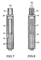
- the continuous casting mold 15 has three mold cavities 15a arranged in a row, which will be discussed in more detail in connection with FIGS. 2 to 6. In FIG. 1, the vertical longitudinal axes of these mold cavities 15a lie in a plane perpendicular to the plane of the drawing. With such a continuous casting mold 15, three continuous casting blocks 17 can be produced at the same time (see also FIG. 8).
- the continuous casting mold 16 has a single but much larger mold cavity 16a for the production of a single, correspondingly thicker continuous casting block 18 (FIG. 7).
- a vacuum valve 19 and 20 is arranged below each mold 15 and 16, respectively, which is firmly connected to the associated mold.
- a discharge chamber 23 or 24 is connected to the two molds 15 and 16, in each of which a discharge device 25 or 26 is arranged, which is embodied as a piston rod and connected to a hydraulic drive, not shown here is.
- the vacuum valve 21 or 22 is in each case firmly connected to the associated trigger chamber 23 or 24.
- the vacuum valves 19/21 and 20/22 can be closed and the valves in question can be separated from one another, so that in each case the discharge chamber 23 or 24 which is not currently in Melting position located mold belongs, extended laterally and can be brought into the position 23 'shown in dashed lines. In this position, the finished block or the finished blocks can cool completely and after opening the vacuum valve 21 'can be removed from the discharge chamber 23'.
- the vacuum valves 21 and 22 are not absolutely necessary. For example, it is possible to keep the extraction chambers 23 and 24 in constant connection with the associated molds and to remove the finished blocks through side doors (not shown here). However, the vacuum valves 19 and 20 are absolutely necessary so that the vacuum in the melting chamber 2 can be maintained.
- FIG. 1 can still be seen that above the continuous casting molds 15 and 16, a further electron beam gun 7 is arranged in such a position that the mold cavity 16a of the continuous casting mold, which is no longer in the fall path of the melt, can also be heated by means of this electron beam gun.
- the so-called Deflection area of the electron beam 7a has three distinctive positions, which are characterized by the dashed lines a, b and c.
- position a the electron beam 7a heats the three upper troughs 13b of the intermediate crucible 13 arranged between the charging device 8 and the continuous casting mold 15.
- the overflowing amount of melt can be precisely dosed or brought to a complete standstill with respect to each upper trough when, for example, a mold change takes place should.
- the melt is temporarily "frozen” by reducing the power in the upper gutters, the melt level in the intermediate crucible 13 rising slightly for a short time.
- the melting process must also be interrupted , so that inhomogeneities also occur in the melt composition, ie each block is no longer homogeneous over its entire length.
- the short interruption possible according to the invention makes this effect negligible.
- the change process of the triple mold 15 is shown in plan view.
- the melt guide element 12, which is designed as an intermediate crucible 13 is arranged in a stationary manner, and the three upper runner channels 13b define the path of the melt that enters the three mold cavities 15a.
- the mold 15 can be brought into the position 15 ', while the mold 16 can be brought into the place of the mold 15 when using an arrangement according to Figure 1.
- Figure 2 shows, however, that both molds can be identical, so that three continuous casting blocks 17 can be produced with each of the two molds.
- Figure 3 shows that the mold change is not limited to a pivoting movement about an axis of rotation 3.
- two molds 15 and 16 can also be replaced by a linear movement in the direction of the double arrow 27.
- there are fixed drop paths for the melt due to the fixed attachment of the intermediate crucible 13 with the overflow channels 13b.
- FIG. 5 and 6 show two further exemplary embodiments with stationary molds 15 and 16, in which the displacement of the falling path of the melt is effected in each case by a linear movement of the intermediate crucible 13.
- the intermediate crucible 13 is displaced in the direction of its longest axis from one mold 15 to the other mold 16.
- the intermediate crucible 13 is displaced from one mold 15 to the other mold 16 transversely to its longest axis.
- the formation of the melt guide element 12 as an intermediate crucible 13 brings with it the great advantage that in the intermediate crucible an additional cleaning of the melt by evaporation of undesirable additives and the expulsion of gases can take place as well as the so-called "gravity cleaning" by depositing heavy impurities on the bottom of the intermediate crucible and by lifting light impurities as slag to the melt surface.
- the use of the intermediate crucible 13 is a very critical component with regard to the evaporation of volatile elements described at the outset, so that the shortest possible interruption in operation should be aimed at, ie the mold change according to the invention combined with the shortest possible time for changing the relative assignment of the fall path the melt to the mold used in each case.
- the withdrawal device 25 consists of three piston rods which can be driven independently of one another.
- the speed of movement of each individual piston rod is regulated here by a level monitoring of the melt level within the continuous casting mold 15 which is known per se.
- a continuous casting block 18 with a correspondingly larger block cross section is to be produced by means of the continuous casting mold 16
- FIGS. 7 and 8 it can also be seen from FIGS. 7 and 8 that in this case only one vacuum valve 19 and 20 is located between the molds 15 and 16 and the discharge chambers 23 and 24, respectively. In such a case, the blocks can be removed - as already described above - through a door (not shown here) in a side wall of the extraction chamber 23 or 24.
Landscapes
- Engineering & Computer Science (AREA)
- Mechanical Engineering (AREA)
- Chemical & Material Sciences (AREA)
- Manufacturing & Machinery (AREA)
- Materials Engineering (AREA)
- Metallurgy (AREA)
- Organic Chemistry (AREA)
- Crucibles And Fluidized-Bed Furnaces (AREA)
- Continuous Casting (AREA)
- Furnace Details (AREA)
- Tunnel Furnaces (AREA)
Applications Claiming Priority (2)
| Application Number | Priority Date | Filing Date | Title |
|---|---|---|---|
| DE3740530 | 1987-11-30 | ||
| DE19873740530 DE3740530A1 (de) | 1987-11-30 | 1987-11-30 | Schmelzofen zum erzeugen von strangguss-bloecken in einer schutzgasatmosphaere |
Publications (2)
| Publication Number | Publication Date |
|---|---|
| EP0318881A1 true EP0318881A1 (fr) | 1989-06-07 |
| EP0318881B1 EP0318881B1 (fr) | 1991-10-16 |
Family
ID=6341566
Family Applications (1)
| Application Number | Title | Priority Date | Filing Date |
|---|---|---|---|
| EP88119763A Expired - Lifetime EP0318881B1 (fr) | 1987-11-30 | 1988-11-26 | Four de fusion pour la fabrication de bandes sous atmosphère protectrice |
Country Status (3)
| Country | Link |
|---|---|
| US (1) | US4821791A (fr) |
| EP (1) | EP0318881B1 (fr) |
| DE (2) | DE3740530A1 (fr) |
Cited By (2)
| Publication number | Priority date | Publication date | Assignee | Title |
|---|---|---|---|---|
| DE19743695A1 (de) * | 1997-10-02 | 1999-06-10 | Ald Vacuum Techn Gmbh | Verfahren und Vorrichtung zum Einschmelzen und Umschmelzen von Materialien zu Blöcken |
| WO2013093055A1 (fr) * | 2011-12-23 | 2013-06-27 | Ald Vacuum Technologies Gmbh | Procédé et dispositif permettant de faire fonctionner un four de fusion à faisceau électronique |
Families Citing this family (6)
| Publication number | Priority date | Publication date | Assignee | Title |
|---|---|---|---|---|
| FR2691655A1 (fr) * | 1992-05-26 | 1993-12-03 | Cezus Co Europ Zirconium | Procédé d'élaboration d'un lingot annulaire en zirconium ou alliage et dispositif et utilisation correspondants. |
| DE4332026C2 (de) * | 1993-09-21 | 1995-11-16 | Schultheiss Georg Electronic | Vorrichtung zum Stranggießen |
| DE19650856B4 (de) * | 1996-12-07 | 2005-10-20 | Ald Vacuum Techn Ag | Vorrichtung und Verfahren zur Herstellung von gerichtet erstarrten Stranggußblöcken |
| KR101175400B1 (ko) * | 2008-08-28 | 2012-08-20 | 현대제철 주식회사 | 턴디쉬 폐열을 이용한 몰드 파우더 공급장치 |
| US10155263B2 (en) | 2012-09-28 | 2018-12-18 | Ati Properties Llc | Continuous casting of materials using pressure differential |
| CN111659865B (zh) * | 2020-06-20 | 2021-07-20 | 南京工业大学 | 钛合金棒材高效率高通量结晶装置 |
Citations (5)
| Publication number | Priority date | Publication date | Assignee | Title |
|---|---|---|---|---|
| DE1105534B (de) * | 1959-05-14 | 1961-04-27 | Stauffer Chemical Co | Hochvakuumschmelz- bzw. -gussverfahren und Vorrichtung zu dessen Durchfuehrung |
| FR1273341A (fr) * | 1960-11-14 | 1961-10-06 | Heraeus Gmbh W C | Dispositif de changement de creuset de fusion pour four à arc sous vide |
| DE1121281B (de) * | 1959-11-07 | 1962-01-04 | Heraeus Gmbh W C | Schmelzanlage zum Schmelzen von Metallen unter reduziertem Druck |
| FR2145600A1 (fr) * | 1971-07-14 | 1973-02-23 | Leybold Heraeus Verwaltung | |
| US4130416A (en) * | 1973-04-19 | 1978-12-19 | Zaboronok Georgy F | Method of preparing a furnace charge when smelting refractory metals and alloys |
Family Cites Families (10)
| Publication number | Priority date | Publication date | Assignee | Title |
|---|---|---|---|---|
| US27945A (en) * | 1860-04-17 | Henry belfield | ||
| GB861567A (en) * | 1956-08-13 | 1961-02-22 | Stauffer Chemical Co | Continuous vacuum casting process |
| US3273212A (en) * | 1959-01-16 | 1966-09-20 | Republic Steel Corp | Method of operating an electric furnace |
| US3237254A (en) * | 1962-06-26 | 1966-03-01 | Stauffer Chemical Co | Vacuum casting |
| US4027722A (en) * | 1963-02-01 | 1977-06-07 | Airco, Inc. | Electron beam furnace |
| FR84908E (fr) * | 1963-04-04 | 1965-05-07 | Commissaria A L En Atomique | Perfectionnements apportés aux procédés de coulée, notamment de lingots, et en particulier de carbure d'uranium |
| USRE27945E (en) | 1968-04-03 | 1974-03-26 | Apparatus for processing molten metal in a vacuum | |
| US3821979A (en) * | 1970-12-07 | 1974-07-02 | B Paton | Electron-beam furnace for remelting electrodes |
| BE794346A (fr) * | 1972-02-04 | 1973-05-16 | Mitsubishi Heavy Ind Ltd | Procede et appareil pour la fabrication de corps tubulaires |
| DE3527628A1 (de) * | 1985-08-01 | 1987-02-05 | Leybold Heraeus Gmbh & Co Kg | Verfahren und vorrichtung zum einschmelzen und umschmelzen von partikelfoermigen metallen zu straengen, insbesondere zu brammen |
-
1987
- 1987-11-30 DE DE19873740530 patent/DE3740530A1/de not_active Withdrawn
-
1988
- 1988-02-19 US US07/157,910 patent/US4821791A/en not_active Expired - Fee Related
- 1988-11-26 DE DE8888119763T patent/DE3865644D1/de not_active Expired - Fee Related
- 1988-11-26 EP EP88119763A patent/EP0318881B1/fr not_active Expired - Lifetime
Patent Citations (5)
| Publication number | Priority date | Publication date | Assignee | Title |
|---|---|---|---|---|
| DE1105534B (de) * | 1959-05-14 | 1961-04-27 | Stauffer Chemical Co | Hochvakuumschmelz- bzw. -gussverfahren und Vorrichtung zu dessen Durchfuehrung |
| DE1121281B (de) * | 1959-11-07 | 1962-01-04 | Heraeus Gmbh W C | Schmelzanlage zum Schmelzen von Metallen unter reduziertem Druck |
| FR1273341A (fr) * | 1960-11-14 | 1961-10-06 | Heraeus Gmbh W C | Dispositif de changement de creuset de fusion pour four à arc sous vide |
| FR2145600A1 (fr) * | 1971-07-14 | 1973-02-23 | Leybold Heraeus Verwaltung | |
| US4130416A (en) * | 1973-04-19 | 1978-12-19 | Zaboronok Georgy F | Method of preparing a furnace charge when smelting refractory metals and alloys |
Cited By (2)
| Publication number | Priority date | Publication date | Assignee | Title |
|---|---|---|---|---|
| DE19743695A1 (de) * | 1997-10-02 | 1999-06-10 | Ald Vacuum Techn Gmbh | Verfahren und Vorrichtung zum Einschmelzen und Umschmelzen von Materialien zu Blöcken |
| WO2013093055A1 (fr) * | 2011-12-23 | 2013-06-27 | Ald Vacuum Technologies Gmbh | Procédé et dispositif permettant de faire fonctionner un four de fusion à faisceau électronique |
Also Published As
| Publication number | Publication date |
|---|---|
| EP0318881B1 (fr) | 1991-10-16 |
| US4821791A (en) | 1989-04-18 |
| DE3740530A1 (de) | 1989-06-08 |
| DE3865644D1 (de) | 1991-11-21 |
Similar Documents
| Publication | Publication Date | Title |
|---|---|---|
| DE69922698T2 (de) | Schmelz-/warmhalteofen für aluminiumblock | |
| DE2625314A1 (de) | Verfahren und vorrichtung zur eingabe von glas-rohmaterialien in einen kontinuierlich arbeitenden, der glasherstellung dienenden wannen-schmelzofen | |
| DE1291760B (de) | Verfahren und Vorrichtung zum diskontinuierlichen und kontinuierlichen Vakuum-Schmelzen und -Giessen von Staehlen und stahlaehnlichen Legierungen (Superiegierungen) | |
| DE3000486A1 (de) | Spritzgussvorrichtung und spritzgussverfahren | |
| DE3527628A1 (de) | Verfahren und vorrichtung zum einschmelzen und umschmelzen von partikelfoermigen metallen zu straengen, insbesondere zu brammen | |
| DE2706347A1 (de) | Verfahren und vorrichtung zum herstellen von glasfasern | |
| DE2926194C1 (de) | Giessvorrichtung zur Herstellung metallischer Gussstuecke mit orientierter Struktur | |
| DE2451921C3 (de) | Verfahren und integrierte Ofenanlage zum kontinuierlichen Erzeugen von einzelnen Gußstücken | |
| DE4116073A1 (de) | Verfahren zum giessen von dentalmetallen | |
| DE3718953C2 (de) | Verfahren zur Herstellung von Glasprodukten mittels Elektroschmelzen sowie Elektroschmelzeinrichtung hierfür | |
| EP0318881B1 (fr) | Four de fusion pour la fabrication de bandes sous atmosphère protectrice | |
| DE2942724A1 (de) | Verfahren zur thermischen behandlung von glastafeln | |
| EP1072696A1 (fr) | Appareillage et sa méthode de mise en oeuvre pour fabriquer des lingots à solidification directionnelle | |
| DE820037C (de) | Verfahren und Vorrichtung zum Angiessen der Brueckenleisten an die stromfuehrenden Fahnen von Akkumulatorenplatten | |
| DD298304A5 (de) | Verfahren und vorrichtung zum beschicken eines ofens mit metallhaltigen materialien und deren vorwaermung | |
| AT394545B (de) | Verfahren und vorrichtung fuer die regelung der kontinuierlichen zufuehrung von schmelzfluessigem material zu einer faserproduktionseinheit | |
| DE2821130C2 (de) | Verdampfertiegel mit Zuführung des Verdampfungsmaterials in Form von Stangen durch den Tiegelboden | |
| DE69027771T2 (de) | Induktionsschmelz- und -giessofen | |
| DE1596578A1 (de) | Verfahren,Anlage und Vorrichtung zum Herstellen von fadenbildenden mineralischen Werkstoffen sowie zum Herstellen und Aufhaspeln der Faeden | |
| DE2150904A1 (de) | Elektronenstrahlofen | |
| DE60012136T2 (de) | Eintragemaschine für Glasgegenstände | |
| DE1966644A1 (de) | Anlage zur herstellung von umschmelzbloecken | |
| DE723965C (de) | Einrichtung zur Herstellung von Glasplatten | |
| DE66919C (de) | Verfahren zur Herstellung von Tafelglas | |
| DE2728530A1 (de) | Vorrichtung zum elektroschlackeumschmelzen und auftragsschweissen von metallen |
Legal Events
| Date | Code | Title | Description |
|---|---|---|---|
| PUAI | Public reference made under article 153(3) epc to a published international application that has entered the european phase |
Free format text: ORIGINAL CODE: 0009012 |
|
| AK | Designated contracting states |
Kind code of ref document: A1 Designated state(s): BE DE FR GB |
|
| 17P | Request for examination filed |
Effective date: 19890608 |
|
| 17Q | First examination report despatched |
Effective date: 19910110 |
|
| GRAA | (expected) grant |
Free format text: ORIGINAL CODE: 0009210 |
|
| PGFP | Annual fee paid to national office [announced via postgrant information from national office to epo] |
Ref country code: DE Payment date: 19910918 Year of fee payment: 4 |
|
| PGFP | Annual fee paid to national office [announced via postgrant information from national office to epo] |
Ref country code: FR Payment date: 19911014 Year of fee payment: 4 |
|
| AK | Designated contracting states |
Kind code of ref document: B1 Designated state(s): BE DE FR GB |
|
| PGFP | Annual fee paid to national office [announced via postgrant information from national office to epo] |
Ref country code: BE Payment date: 19911106 Year of fee payment: 4 |
|
| GBT | Gb: translation of ep patent filed (gb section 77(6)(a)/1977) | ||
| REF | Corresponds to: |
Ref document number: 3865644 Country of ref document: DE Date of ref document: 19911121 |
|
| ET | Fr: translation filed | ||
| PLBE | No opposition filed within time limit |
Free format text: ORIGINAL CODE: 0009261 |
|
| STAA | Information on the status of an ep patent application or granted ep patent |
Free format text: STATUS: NO OPPOSITION FILED WITHIN TIME LIMIT |
|
| 26N | No opposition filed | ||
| PG25 | Lapsed in a contracting state [announced via postgrant information from national office to epo] |
Ref country code: GB Effective date: 19921126 |
|
| PG25 | Lapsed in a contracting state [announced via postgrant information from national office to epo] |
Ref country code: BE Effective date: 19921130 |
|
| BERE | Be: lapsed |
Owner name: LEYBOLD A.G. Effective date: 19921130 |
|
| GBPC | Gb: european patent ceased through non-payment of renewal fee |
Effective date: 19921126 |
|
| PG25 | Lapsed in a contracting state [announced via postgrant information from national office to epo] |
Ref country code: FR Effective date: 19930730 |
|
| PG25 | Lapsed in a contracting state [announced via postgrant information from national office to epo] |
Ref country code: DE Effective date: 19930803 |
|
| REG | Reference to a national code |
Ref country code: FR Ref legal event code: ST |