EP0318905A2 - Verfahren und Vorrichtung zur Herstellung von Regenfallrohren - Google Patents
Verfahren und Vorrichtung zur Herstellung von Regenfallrohren Download PDFInfo
- Publication number
- EP0318905A2 EP0318905A2 EP88119856A EP88119856A EP0318905A2 EP 0318905 A2 EP0318905 A2 EP 0318905A2 EP 88119856 A EP88119856 A EP 88119856A EP 88119856 A EP88119856 A EP 88119856A EP 0318905 A2 EP0318905 A2 EP 0318905A2
- Authority
- EP
- European Patent Office
- Prior art keywords
- mandrel
- bending
- tubular profile
- section
- folded
- Prior art date
- Legal status (The legal status is an assumption and is not a legal conclusion. Google has not performed a legal analysis and makes no representation as to the accuracy of the status listed.)
- Granted
Links
Images



Classifications
-
- B—PERFORMING OPERATIONS; TRANSPORTING
- B21—MECHANICAL METAL-WORKING WITHOUT ESSENTIALLY REMOVING MATERIAL; PUNCHING METAL
- B21C—MANUFACTURE OF METAL SHEETS, WIRE, RODS, TUBES, PROFILES OR LIKE SEMI-MANUFACTURED PRODUCTS OTHERWISE THAN BY ROLLING; AUXILIARY OPERATIONS USED IN CONNECTION WITH METAL-WORKING WITHOUT ESSENTIALLY REMOVING MATERIAL
- B21C37/00—Manufacture of metal sheets, rods, wire, tubes, profiles or like semi-manufactured products, not otherwise provided for; Manufacture of tubes of special shape
- B21C37/06—Manufacture of metal sheets, rods, wire, tubes, profiles or like semi-manufactured products, not otherwise provided for; Manufacture of tubes of special shape of tubes or metal hoses; Combined procedures for making tubes, e.g. for making multi-wall tubes
- B21C37/10—Making tubes with seams being neither welded nor soldered, e.g. riveted seams
- B21C37/101—Making of the seams
-
- B—PERFORMING OPERATIONS; TRANSPORTING
- B21—MECHANICAL METAL-WORKING WITHOUT ESSENTIALLY REMOVING MATERIAL; PUNCHING METAL
- B21C—MANUFACTURE OF METAL SHEETS, WIRE, RODS, TUBES, PROFILES OR LIKE SEMI-MANUFACTURED PRODUCTS OTHERWISE THAN BY ROLLING; AUXILIARY OPERATIONS USED IN CONNECTION WITH METAL-WORKING WITHOUT ESSENTIALLY REMOVING MATERIAL
- B21C37/00—Manufacture of metal sheets, rods, wire, tubes, profiles or like semi-manufactured products, not otherwise provided for; Manufacture of tubes of special shape
- B21C37/06—Manufacture of metal sheets, rods, wire, tubes, profiles or like semi-manufactured products, not otherwise provided for; Manufacture of tubes of special shape of tubes or metal hoses; Combined procedures for making tubes, e.g. for making multi-wall tubes
- B21C37/10—Making tubes with seams being neither welded nor soldered, e.g. riveted seams
Definitions
- the invention relates to a method and a device for the production of folded pluggable rainwater downpipes, in particular according to DIN 18 461, by bending formed from non-ferrous metals, preferably zinc and copper material, sheet metal strips of a certain cut width and cut length to pre-rounded pipe profiles, the longitudinal edges of which are edged under Form a seam connection merged and bent flat on the outer circumference of the tubular profile.
- non-ferrous metals preferably zinc and copper material
- sheet metal strips of a certain cut width and cut length to pre-rounded pipe profiles, the longitudinal edges of which are edged under Form a seam connection merged and bent flat on the outer circumference of the tubular profile.
- foldable, pluggable rainwater downpipes are standardized, which are made from sheet metal strips of non-ferrous metal with a cutting width of 200 to 500 mm by bending, the longitudinal edges of which are connected to each other via a fold connection lying flat on the outer circumference of the downpipe.
- the diameter at the narrower pipe end is designed to be insertable into the further pipe end of the subsequent downpipe in such a way that the inside diameter at the narrower pipe end is approximately twice the wall thickness smaller than at the further pipe end.
- downpipes of this type can be produced from sheet metal strips of the desired cut length cut from an endless sheet metal strip of the desired cutting width in such a way that the sheet metal strip is inserted into a bending section and into a reciprocating pulling carriage which guides the sheet metal strip through the bending section pulls through, is clamped. With each backward movement of the slide, the sheet metal strip is held and at the forward movement in the outlet direction is released. The initially flat, but then more and more curved bending shape of the bending section narrows to a cylindrical fold shape. The two longitudinal edges of the bending shape are turned inwards by approximately 180 °.
- the sheet metal strip is supported in these envelopes in the course of the deformation until the envelopes are finally omitted and the longitudinal edges of the sheet metal strip reach a folding device in which one longitudinal edge is bent to the standing seam and the other to the Z fold.
- a subsequent closing device the two folds are brought together, the standing seam is covered by the Z fold and both folds are bent through 90 °, as a result of which the fold connection comes to lie flat on the outer circumference of the downpipe.
- the downpipe is guided over a mandrel corresponding to its width, is compensated for by the deformation stresses of the sheet metal strip, and the surface lines of the downpipes are smoothed.
- This device is perfected in that, according to DE-OS 26 29 559, the endless sheet metal strip is inserted directly into the bending section and an endless tube is made from it, from which the downpipes of the desired length can be cut to length using a so-called flying saw.
- the object of the present invention is therefore to produce downpipes of the form described in the introduction in such a way that their outer surface has a high quality and is free from scratches and scratches.
- the fold connection of the pipe profiles which have been rounded by roll profiling, is formed in several sections by bending with rotating tool movement, each pipe profile is transported in the outlet direction by the length of the section of the fold connection formed in each case and the pipe section in the manufacture of the last section of the fold connection this section is manufactured expanded.
- the method according to the invention permits the mechanical production of rebated connections which, based on the outer circumference of the downpipe, can lie completely inside, completely outside or partly outside and partly inside.
- the downpipes have a high surface quality, as they are practically free of scratches and / or scratches, which ensures a uniform wall thickness.
- the device for carrying out the method according to the invention consists of a roll profiling device formed from a plurality of drivable bending roller pairs, the axes of which lie in the bending plane, for bending the sheet metal strips into pre-rounded tubular profiles, a stationary, essentially cylindrical mandrel with a conically or cylindrically widened section on the inlet side and with in Direction of outlet lying axis for receiving the pre-rounded tubular profile, counter-holder attached to the side of the mandrel, displaceable transversely to the axis of the mandrel, for pressing the tubular profile onto the mandrel and a reversible one of several that can be driven Bending roll pairs, the axes of which are perpendicular or inclined to the bending plane, formed folding tool for edging and compressing the folds and folding the fold connection.
- the mandrel is divided in the longitudinal direction in such a way that the two segments can be displaced relative to one another along the parting plane emerging at the end faces of the mandrel, which is inclined with respect to the plane including the axis of the mandrel.
- the diameter of the mandrel is reduced perpendicular to the plane including the axis of the mandrel, so that the tubular profile can be pulled off the mandrel.
- the mandrel is divided in the longitudinal direction along a dividing plane emerging at the end faces of the mandrel and the two segments can be spread apart.
- the folded connection of the tubular profile is made; by reducing the spread, the diameter of the mandrel decreases perpendicularly on the plane comprising the axis of the mandrel and the tubular profile can be removed from the mandrel.
- the mandrel can also be made of a rubber-elastic material and its effective diameter can be adjusted by compressing the end faces. By reducing the pressure load, the effective diameter of the mandrel is reduced to the initial size, which is smaller than the diameter of the tube profile, and the tube profile can be removed from the mandrel.
- the length of the mandrel is at least 10%, preferably 10 to 50% of the length of the tubular profile.
- the folding tool is designed such that the tubular profile is also transported when it moves in the outlet direction.
- a rolling straightening section can be arranged downstream of the folding tool, in which the tubular profile is straightened.
- a sheet metal strip (5) corresponding to the desired length of the downpipe is cut to length from the sheet metal strip (2) of a certain cutting width and passes through the two pairs of straightening rollers (6 ) into the six Formed roll forming device, in which the sheet metal strip (5) is rounded to a tubular profile (8), is inserted.
- the tubular section (8) is then pushed with its first section onto the stationary arranged cylindrical mandrel (9), which emerges in the longitudinal direction along a plane (10) emerging at the end faces of the mandrel (9) and inclined with respect to the plane including the axis of the mandrel.
- the length of the mandrel (9) is approximately 10% of the length of the tubular profile (8).
- the inlet-side section (9 ') of the mandrel has a conical outer shape.
- the folding tool (15) which is reversibly guided in the guide rails (13) of the support frame (14) via the guide rollers (12), moves against the outlet direction via the mandrel (9), so that the driven pairs of bending rollers (16) extend the longitudinal edges of the tubular profile (8). Edge up to folds (17), bring them together to form a fold connection and bend the latter by 90 ° onto the outer circumference of the downpipe.
- the tubular profile (8) is pressed firmly onto the mandrel (9), so that the longitudinal edges without problems for producing the folded connection in the bending section of the Folding tool (15) can run in.
- the tubular profile (8) is moved forward by the seaming tool (15) moving in the outlet direction.
- the conically widened insertion end of the tubular profile (9) is formed.
- the two segments (11, 11 ') of the mandrel (9) are displaced towards one another along the division plane (10), the diameter of the mandrel (9) is reduced and the tubular profile (8) can be pulled off the mandrel (9).
Landscapes
- Engineering & Computer Science (AREA)
- Mechanical Engineering (AREA)
- Bending Of Plates, Rods, And Pipes (AREA)
- Injection Moulding Of Plastics Or The Like (AREA)
- Vehicle Body Suspensions (AREA)
- Butt Welding And Welding Of Specific Article (AREA)
- Superconductors And Manufacturing Methods Therefor (AREA)
- Manufacture, Treatment Of Glass Fibers (AREA)
- Transition And Organic Metals Composition Catalysts For Addition Polymerization (AREA)
Abstract
Description
- Die Erfindung betrifft ein Verfahren und eine Vorrichtung zur Herstellung von gefalzten steckbaren Regenfallrohren, insbesondere nach DIN 18 461, durch Biegeumformen von aus NE-Metall, vorzugsweise Zink- und Kupferwerkstoff, bestehenden Blechstreifen bestimmter Zuschnittbreite und Zuschnittlänge zu vorgerundeten Rohrprofilen, deren Längsränder aufgekantet, unter Bildung einer Falzverbindung zusammengeführt und flach auf den Außenumfang des Rohrprofils umgebogen werden.
- Durch DIN 18 461 sind gefalzte steckbare Regenfallrohre genormt, die aus Blechstreifen von NE-Metall von 200 bis 500 mm Zuschnittbreite durch Biegeumformen hergestellt werden, wobei deren Längsränder über eine flach auf dem Außenumfang der Regenfallrohre liegende Falzverbindung miteinander verbunden sind. Der Durchmesser am engeren Rohrende ist passend in das weitere Rohrende des nachfolgenden Regenfallrohrs in der Weise einsteckbar gestaltet, daß der Innendurchmesser am engeren Rohrende um etwa den Betrag der doppelten Wanddicke kleiner als am weiteren Rohrende ist.
- Nach der DE-PS 11 70 891 lassen sich derartige Regenfallrohre aus von einem endlosen Blechband gewünschter Zuschnittbreite abgelängten Blechstreifen gewünschter Zuschnittlänge in der Weise herstellen, daß der Blechstreifen in eine Biegestrecke eingeführt und in einen hin- und herbewegbaren Ziehschlitten, der den Blechstreifen durch die Biegestrecke hindurchzieht, eingespannt wird. Bei jeder Rückwärtsbewegung des Ziehschlittens wird der Blechstreifen festgehalten und bei der Vorwärtsbewegung in Auslaufrichtung freigegeben. Die zunächst flache, dann aber mehr und mehr nach unten gewölbte Biegeform der Biegestrecke verengt sich zu einer zylindrischen Falzform. Die beiden Längsränder der Biegeform sind um etwa 180° nach innen umgeschlagen. In diesen Umschlägen stützt sich der Blechstreifen im Verlauf der Verformung ab, bis schließlich die Umschläge entfallen und die Längskanten des Blechstreifens in eine Falzeinrichtung gelangen, in der der eine Längsrand zum Stehfalz und der andere zum Z-Falz gebogen werden. In einer nachfolgenden Schließvorrichtung werden die beiden Falze zusammengeführt, der Stehfalz wird dabei von dem Z-Falz überdeckt und beide Falze um 90° umgebogen, wodurch die Falzverbindung flach auf dem Außenumfang des Regenfallrohrs zu liegen kommt. Nach dem Verlassen der Schließvorrichtung wird das Regenfallrohr über einen seiner Weite entsprechenden Dorn geführt, durch den Verformungsspannungen des Blechstreifens ausgeglichen und die Mantellinien der Regenfallrohre geglättet werden. Diese Vorrichtung ist dadurch vervollkommnet, daß gemäß DE-OS 26 29 559 das endlose Blechband unmittelbar in die Biegestrecke eingeführt und daraus ein endloses Rohr gefertigt wird, von dem dann Regenfallrohre gewünschter Länge mit Hilfe einer sogenannten fliegenden Säge abgelängt werden können.
- Die vorstehend beschriebenen Einrichtungen zur Herstellung von gefalzten Regenfallrohren haben sich zwar seit vielen Jahren in der Praxis bewährt, ihnen haftet jedoch der Nachteil an, daß sich beim Ziehen der Blechstreifen bzw. des Blechbandes durch die Biegeform Riefen und/oder Kratzer auf der Außenoberfläche der Regenfallrohre bilden, die die ästhetische Wirkung der Regenfallrohre erheblich beeinträchtigen und zu einer ungleichmäßigen Wanddicke führen.
- Aufgabe der vorliegenden Erfindung ist es deshalb, Regenfallrohre der eingangs beschriebenen Form so herzustellen, daß ihre Außenoberfläche eine hohe Güte aufweist und frei von Riefen und Kratzer ist.
- Diese Aufgabe wird dadurch gelöst, daß die Falzverbindung der durch Walzprofilieren vorgerundeten Rohrprofile in mehreren Abschnitten durch Biegeumformen mit drehender Werkzeugbewegung geformt, jedes Rohrprofil um die Länge des jeweils geformten Abschnitts der Falzverbindung in Auslaufrichtung transportiert und bei der Herstellung des letzten Abschnitts der Falzverbindung das Rohrprofil in diesem Abschnitt aufgeweitet gefertigt wird. Das erfindungsgemäße Verfahren erlaubt die maschinelle Herstellung Falzverbindungen, die, bezogen auf den Außenumfang des Regenfallrohrs, vollständig innen, vollständig außen oder zu einem Teil außen und zu einem Teil innen liegen kann. Die Regenfallrohre besitzen eine hohe Oberflächengüte, da sie praktisch frei von Riefen und/oder Kratzern sind und damit eine gleichmäßige Wanddicke gewährleistet ist.
- Die Vorrichtung zur Durchführung des Verfahrens besteht erfindungsgemäß aus einer aus mehreren antreibbaren Biegewalzenpaaren, deren Achsen in der Biegeebene liegen, gebildete Walzprofiliereinrichtung zum Biegeumformen der Blechstreifen zu vorgerundeten Rohrprofilen, einem ortsfest angeordneten, im wesentlichen zylindrischen Dorn mit einlaufseitig konisch oder zylindrisch aufgeweitetem Abschnitt und mit in Auslaufrichtung liegender Achse für die Aufnahme des vorgerundeten Rohrprofils, seitlich des Dorn angebrachte, quer zur Achse des Dorns verschiebliche Gegenhalter zum Andrücken des Rohrprofils auf den Dorn und einem reversierbaren, aus mehreren antreibbaren Biegewalzenpaaren, deren Achsen senkrecht oder geneigt zur Biegeebene stehen, gebildeten Falzwerkzeug zum Aufkanten und Zusammendrücken der Falze und Umlegen der Falzverbindung.
- Nach einem besonderen Merkmal der Vorrichtung ist der Dorn in Längsrichtung so geteilt, daß die zwei Segmente entlang der an den Stirnseiten des Dorns austretenden Teilungsebene, die gegenüber der die Achse des Dorns einschließenden Ebene geneigt ist, gegeneinander verschiebbar sind. Beim Verschieben der Segmente gegeneinander wird der Durchmesser des Dorns senkrecht zu der die Achse des Dorns einschließenden Ebene verkleinert, so daß das Rohrprofil von dem Dorn abgezogen werden kann.
- Die gleiche Wirkung läßt sich auch dadurch erreichen, daß der Dorn in Längsrichtung entlang einer an den Stirnseiten des Dorns austretenden Teilungsebene geteilt ist und die zwei Segmente gegeneinander spreizbar sind. In gespreiztem Zustand wird die Falzverbindung des Rohrprofils hergestellt; durch Zurücknahme der Spreizung verkleinert sich der Durchmesser des Dorns senkrecht an der die Achse des Dorns umfassenden Ebene und das Rohrprofil kann von dem Dorn abgenommen werden.
- Der Dorn kann auch aus einem gummielastischen Werkstoff bestehen und sein Wirkdurchmesser durch Druckbelastung der Stirnflächen einstellbar sein. Durch Abbau der Druckbelastung geht der Wirkdurchmesser des Dorns auf die Ausgangsgröße, die kleiner als der Durchmesser des Rohrprofils ist, zurück und das Rohrprofil kann von dem Dorn entfernt werden.
- Nach einer vorzugsweisen Ausgestaltung der Vorrichtung beträgt die Länge des Dorns wenigstens 10 %, vorzugsweise 10 bis 50 % der Länge des Rohrprofils.
- Nach einem weiteren Erfindungsmerkmal ist das Falzwerkzeug so ausgebildet, daß bei dessen Bewegung in Auslaufrichtung das Rohrprofil mittransportiert wird.
- Falls erforderlich, kann dem Falzwerkzeug noch eine Walzrichtstrecke nachgeordnet sein, in der das Rohrprofil gerichtet wird.
- Die Erfindung ist in den Zeichnungen beispielhaft dargestellt und wird nachfolgend näher erläutert. Es zeigen:
- Fig. 1 eine schematische Darstellung einer Vorrichtung zur Herstellung gefalzter und steckbarer Regenfallrohre.
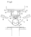
- Fig. 2 einen Querschnitt durch die Vorrichtung im Bereich des Dorns.
- Fig. 3 eine einen Teil des Dorns und das Falzwerkzeug umfassende Seitenansicht.
- Fig. 4 eine einen Teil des Dorns und das Falzwerkzeug umfassende Draufsicht.
- Von dem von dem Haspel (1) ablaufenden Blechband (2) bestimmter Zuschnittbreite wird nach Durchlauf durch die Einzugsrollen (3) mit Hilfe der Trennvorrichtung (4) ein Blechstreifen (5) entsprechend der gewünschten Länge des Regenfallrohrs abgelängt und durch die beiden Richtwalzenpaare (6) hindurch in die aus sechs hintereinander angeordneten angetriebenen Biegewalzenpaaren (7) gebildete Walzprofiliereinrichtung eingeführt, in der der Blechstreifen (5) zu einem Rohrprofil (8) verrundet wird. Anschließend wird das Rohrprofil (8) mit seinem ersten Abschnitt auf den ortsfest angeordneten zylindrischen Dorn (9) aufgeschoben, der in Längsrichtung entlang einer an den Stirnseiten des Dorns (9) austretenden, gegenüber der die Achse des Dorns einschließenden Ebene geneigten Ebene (10) so geteilt ist, daß die zwei Segmente (11,11′) gegeneinander verschiebbar sind. Die Länge des Dorns (9) beträgt etwa 10 % der Länge des Rohrprofils (8). Der einlaufseitige Abschnitt (9′) des Dorns besitzt eine konische Außenform. Das über die Führungsrollen (12) in den Führungsschienen (13) des Tragrahmens (14) reversierbar geführte Falzwerkzeug (15) verfährt entgegen der Auslaufrichtung über den Dorn (9), so daß die angetriebenen Biegewalzenpaare (16) die Längsränder des Rohrprofils (8) zu Falzen (17) aufkanten, diese unter Bildung einer Falzverbindung zusammenführen und letztere um 90° auf den Außenumfang des Regenfallrohrs umbiegen. Durch die seitlich schräg nach oben vom Dorn (9) angeordneten quer zur Achse des Dorns verschiebbaren Gegenhalter (18) wird das Rohrprofil (8) fest auf den Dorn (9) gedrückt, so daß die Längsränder problemlos zur Herstellung der Falzverbindung in die Biegestrecke des Falzwerkzeugs (15) einlaufen können. Nach der Herstellung eines jeden Abschnitts der Falzverbindung wird das Rohrprofil (8) durch das sich in Auslaufrichtung bewegende Falzwerkzeug (15) vorwärts bewegt. Bei der Formgebung des letzten Abschnitts der Falzverbindung wird das konisch aufgeweitete Einsteckende des Rohrprofils (9) geformt. Dann werden die beiden Segmente (11,11′) des Dorns (9) entlang der Teilungsebene (10) gegeneinander verschoben, der Durchmesser des Dorns (9) verkleinert sich und das Rohrprofil (8) kann von dem Dorn (9) abgezogen werden.
Claims (8)
Applications Claiming Priority (2)
| Application Number | Priority Date | Filing Date | Title |
|---|---|---|---|
| DE19873740750 DE3740750A1 (de) | 1987-12-02 | 1987-12-02 | Verfahren und vorrichtung zur herstellung von regenfallrohren |
| DE3740750 | 1987-12-02 |
Publications (3)
| Publication Number | Publication Date |
|---|---|
| EP0318905A2 true EP0318905A2 (de) | 1989-06-07 |
| EP0318905A3 EP0318905A3 (en) | 1990-09-19 |
| EP0318905B1 EP0318905B1 (de) | 1994-06-15 |
Family
ID=6341676
Family Applications (1)
| Application Number | Title | Priority Date | Filing Date |
|---|---|---|---|
| EP88119856A Expired - Lifetime EP0318905B1 (de) | 1987-12-02 | 1988-11-29 | Verfahren und Vorrichtung zur Herstellung von Regenfallrohren |
Country Status (4)
| Country | Link |
|---|---|
| EP (1) | EP0318905B1 (de) |
| AT (1) | ATE107203T1 (de) |
| DE (2) | DE3740750A1 (de) |
| DK (1) | DK169907B1 (de) |
Cited By (3)
| Publication number | Priority date | Publication date | Assignee | Title |
|---|---|---|---|---|
| WO1991016156A1 (en) * | 1990-04-12 | 1991-10-31 | Die-Craft Engineering Pty. Ltd | Tapered conduit |
| RU2270731C1 (ru) * | 2004-08-09 | 2006-02-27 | Общество с ограниченной ответственностью "Русские карнизы" | Оправка для обжатия труб с внутренним фальцевым швом |
| RU2276627C1 (ru) * | 2004-09-28 | 2006-05-20 | Общество с ограниченной ответственностью "Русские карнизы" | Профилегибочный стан |
Families Citing this family (1)
| Publication number | Priority date | Publication date | Assignee | Title |
|---|---|---|---|---|
| RU2181313C2 (ru) * | 2000-06-13 | 2002-04-20 | Открытое акционерное общество "Череповецкий сталепрокатный завод" | Профилегибочный стан для изготовления труб с фальцевым швом |
Family Cites Families (4)
| Publication number | Priority date | Publication date | Assignee | Title |
|---|---|---|---|---|
| US1408232A (en) * | 1917-05-12 | 1922-02-28 | Frank H Stolp | Method of forming sheet metal |
| US2644416A (en) * | 1949-02-02 | 1953-07-07 | Oldberg Mfg Company | Apparatus for forming tubes |
| GB867915A (en) * | 1956-06-02 | 1961-05-10 | Metal Developments Ltd | Improvements relating to columns |
| DE3022671A1 (de) * | 1980-06-18 | 1982-01-14 | Krückels, Gerhard, Dipl.-Ing., 7860 Schopfheim | Profiliermaschine und verfahren zur herstellung eines profiles |
-
1987
- 1987-12-02 DE DE19873740750 patent/DE3740750A1/de not_active Withdrawn
-
1988
- 1988-11-29 DE DE3850225T patent/DE3850225D1/de not_active Expired - Lifetime
- 1988-11-29 EP EP88119856A patent/EP0318905B1/de not_active Expired - Lifetime
- 1988-11-29 AT AT88119856T patent/ATE107203T1/de not_active IP Right Cessation
- 1988-12-01 DK DK671488A patent/DK169907B1/da not_active IP Right Cessation
Cited By (3)
| Publication number | Priority date | Publication date | Assignee | Title |
|---|---|---|---|---|
| WO1991016156A1 (en) * | 1990-04-12 | 1991-10-31 | Die-Craft Engineering Pty. Ltd | Tapered conduit |
| RU2270731C1 (ru) * | 2004-08-09 | 2006-02-27 | Общество с ограниченной ответственностью "Русские карнизы" | Оправка для обжатия труб с внутренним фальцевым швом |
| RU2276627C1 (ru) * | 2004-09-28 | 2006-05-20 | Общество с ограниченной ответственностью "Русские карнизы" | Профилегибочный стан |
Also Published As
| Publication number | Publication date |
|---|---|
| EP0318905A3 (en) | 1990-09-19 |
| DE3740750A1 (de) | 1989-06-15 |
| DK671488A (da) | 1989-06-03 |
| DK671488D0 (da) | 1988-12-01 |
| EP0318905B1 (de) | 1994-06-15 |
| ATE107203T1 (de) | 1994-07-15 |
| DE3850225D1 (de) | 1994-07-21 |
| DK169907B1 (da) | 1995-04-03 |
Similar Documents
| Publication | Publication Date | Title |
|---|---|---|
| AT390432B (de) | Verfahren zur herstellung eines abstandhalterrahmens und vorrichtung sowie anlage zur durchfuehrung des verfahrens | |
| DE69102000T2 (de) | Rohr und Verfahren zur Herstellung. | |
| EP0205992B1 (de) | Verfahren und Vorrichtung zum Runden von Blechen, insbesondere für Dosenkörper | |
| EP1089835A1 (de) | Verfahren und vorrichtung zum herstellen von längsnahtgeschweissten rohren aus ebenen blechzuschnitten | |
| DE2423279A1 (de) | Aus plattenmaterial durch praegen geformte gegenstaende | |
| DD271159A1 (de) | Herstellungsverfahren fuer erleichterte metallprofile | |
| DE2708458C2 (de) | Vorrichtung zum gemeinsamen Strangpressen von mindestens zwei Verbundprofilen | |
| EP0318905B1 (de) | Verfahren und Vorrichtung zur Herstellung von Regenfallrohren | |
| EP0537594A2 (de) | Flanschverbindungsprofil, insbesondere für Lüftungskanäl-Anlagen | |
| DE2803365A1 (de) | Verfahren und vorrichtung zur herstellung von mit querrippen versehenen rohren | |
| DE69002760T2 (de) | Verfahren zur herstellung quadratischer röhren aus beschichteten stahlbändern. | |
| DE2123628C3 (de) | Verfahren und Vorrichtung zum Herstellen von Metallblechplatten mit rohrartigen Längsdurchgängen für strömende Medien | |
| DE3247200C2 (de) | Verfahren und Biegepresse zum Biegen des Rohrabschnittes eines geraden Rohres zu einem fertigen Rohrbogen | |
| DE69107502T2 (de) | Metallrohrherstellung. | |
| EP0174501B1 (de) | Verfahren zum Runden von Profilstangen aus Metall, insbesondere Aluminium mit nicht abgestützten Stegen, Lippen oder ähnlichen Ausformungen | |
| EP0042450B1 (de) | Verfahren zur Herstellung von Mänteln für Auspufftöpfe mit einer gefalzten Längsnaht und Vorrichtung zur Durchführung dieses Verfahrens | |
| EP0044880A1 (de) | Torblatt für ein Deckenglieder- oder Rolltor; Vorrichtung und Verfahren zur Herstellung eines Torblattes | |
| DE19743436A1 (de) | Verfahren zum Verformen eines Bauteils aus Blech und Vorrichtung hierzu | |
| EP1631399B1 (de) | Verfahren zum biegen eines bahnförmigen stehfalzprofilbleches und einrichtung zur durchführung dieses verfahrens | |
| DE102007008554A1 (de) | Verfahren und Vorrichtung zum Herstellen von Profilen | |
| DE2008277A1 (en) | Spiral grooved flexible tube mfe | |
| DE19906553B4 (de) | Vorrichtung zum randseitigen Profilieren von Blechen oder Blechstreifen | |
| DE19744308C1 (de) | Verfahren zum Umformen eines ebenen Metallbandes zu einem Profil, insbesondere Rohr, durch Ziehprofilieren | |
| AT360313B (de) | Verfahren und vorrichtung zur herstellung einer mit gegengleichen laengsprofilierungen ver- sehenen strebenschlange fuer stahlbauteile | |
| DE28921C (de) | Verfahren und Walzwerk zur Herstellung der Längsnähte an Blechröhren |
Legal Events
| Date | Code | Title | Description |
|---|---|---|---|
| PUAI | Public reference made under article 153(3) epc to a published international application that has entered the european phase |
Free format text: ORIGINAL CODE: 0009012 |
|
| AK | Designated contracting states |
Kind code of ref document: A2 Designated state(s): AT BE CH DE FR GB IT LI LU NL |
|
| PUAL | Search report despatched |
Free format text: ORIGINAL CODE: 0009013 |
|
| AK | Designated contracting states |
Kind code of ref document: A3 Designated state(s): AT BE CH DE FR GB IT LI LU NL |
|
| 17P | Request for examination filed |
Effective date: 19901027 |
|
| 17Q | First examination report despatched |
Effective date: 19921223 |
|
| GRAA | (expected) grant |
Free format text: ORIGINAL CODE: 0009210 |
|
| AK | Designated contracting states |
Kind code of ref document: B1 Designated state(s): AT BE CH DE FR GB IT LI LU NL |
|
| REF | Corresponds to: |
Ref document number: 107203 Country of ref document: AT Date of ref document: 19940715 Kind code of ref document: T |
|
| REF | Corresponds to: |
Ref document number: 3850225 Country of ref document: DE Date of ref document: 19940721 |
|
| ET | Fr: translation filed | ||
| ITF | It: translation for a ep patent filed | ||
| GBT | Gb: translation of ep patent filed (gb section 77(6)(a)/1977) |
Effective date: 19940908 |
|
| PLBE | No opposition filed within time limit |
Free format text: ORIGINAL CODE: 0009261 |
|
| STAA | Information on the status of an ep patent application or granted ep patent |
Free format text: STATUS: NO OPPOSITION FILED WITHIN TIME LIMIT |
|
| 26N | No opposition filed | ||
| PGFP | Annual fee paid to national office [announced via postgrant information from national office to epo] |
Ref country code: LU Payment date: 19961001 Year of fee payment: 9 |
|
| PGFP | Annual fee paid to national office [announced via postgrant information from national office to epo] |
Ref country code: GB Payment date: 19961014 Year of fee payment: 9 |
|
| PGFP | Annual fee paid to national office [announced via postgrant information from national office to epo] |
Ref country code: BE Payment date: 19961015 Year of fee payment: 9 |
|
| PGFP | Annual fee paid to national office [announced via postgrant information from national office to epo] |
Ref country code: FR Payment date: 19961022 Year of fee payment: 9 |
|
| PGFP | Annual fee paid to national office [announced via postgrant information from national office to epo] |
Ref country code: CH Payment date: 19961023 Year of fee payment: 9 |
|
| PGFP | Annual fee paid to national office [announced via postgrant information from national office to epo] |
Ref country code: NL Payment date: 19961024 Year of fee payment: 9 Ref country code: DE Payment date: 19961024 Year of fee payment: 9 |
|
| PGFP | Annual fee paid to national office [announced via postgrant information from national office to epo] |
Ref country code: AT Payment date: 19961025 Year of fee payment: 9 |
|
| PG25 | Lapsed in a contracting state [announced via postgrant information from national office to epo] |
Ref country code: DE Effective date: 19971021 |
|
| PG25 | Lapsed in a contracting state [announced via postgrant information from national office to epo] |
Ref country code: LU Free format text: LAPSE BECAUSE OF NON-PAYMENT OF DUE FEES Effective date: 19971129 Ref country code: GB Free format text: LAPSE BECAUSE OF NON-PAYMENT OF DUE FEES Effective date: 19971129 Ref country code: AT Free format text: LAPSE BECAUSE OF NON-PAYMENT OF DUE FEES Effective date: 19971129 |
|
| PG25 | Lapsed in a contracting state [announced via postgrant information from national office to epo] |
Ref country code: LI Free format text: LAPSE BECAUSE OF NON-PAYMENT OF DUE FEES Effective date: 19971130 Ref country code: FR Free format text: THE PATENT HAS BEEN ANNULLED BY A DECISION OF A NATIONAL AUTHORITY Effective date: 19971130 Ref country code: CH Free format text: LAPSE BECAUSE OF NON-PAYMENT OF DUE FEES Effective date: 19971130 Ref country code: BE Free format text: LAPSE BECAUSE OF NON-PAYMENT OF DUE FEES Effective date: 19971130 |
|
| BERE | Be: lapsed |
Owner name: RHEINZINK G.M.B.H. Effective date: 19971130 |
|
| PG25 | Lapsed in a contracting state [announced via postgrant information from national office to epo] |
Ref country code: NL Free format text: LAPSE BECAUSE OF NON-PAYMENT OF DUE FEES Effective date: 19980601 |
|
| REG | Reference to a national code |
Ref country code: CH Ref legal event code: PL |
|
| GBPC | Gb: european patent ceased through non-payment of renewal fee |
Effective date: 19971129 |
|
| NLV4 | Nl: lapsed or anulled due to non-payment of the annual fee |
Effective date: 19980601 |
|
| REG | Reference to a national code |
Ref country code: FR Ref legal event code: ST |
|
| PG25 | Lapsed in a contracting state [announced via postgrant information from national office to epo] |
Ref country code: IT Free format text: LAPSE BECAUSE OF NON-PAYMENT OF DUE FEES;WARNING: LAPSES OF ITALIAN PATENTS WITH EFFECTIVE DATE BEFORE 2007 MAY HAVE OCCURRED AT ANY TIME BEFORE 2007. THE CORRECT EFFECTIVE DATE MAY BE DIFFERENT FROM THE ONE RECORDED. Effective date: 20051129 |