EP0318995A2 - Pyrotechnical initiator for projectiles - Google Patents
Pyrotechnical initiator for projectiles Download PDFInfo
- Publication number
- EP0318995A2 EP0318995A2 EP88120077A EP88120077A EP0318995A2 EP 0318995 A2 EP0318995 A2 EP 0318995A2 EP 88120077 A EP88120077 A EP 88120077A EP 88120077 A EP88120077 A EP 88120077A EP 0318995 A2 EP0318995 A2 EP 0318995A2
- Authority
- EP
- European Patent Office
- Prior art keywords
- slide
- detonator
- pyrotechnic
- delay
- igniter according
- Prior art date
- Legal status (The legal status is an assumption and is not a legal conclusion. Google has not performed a legal analysis and makes no representation as to the accuracy of the status listed.)
- Granted
Links
- 239000003999 initiator Substances 0.000 title 1
- 238000010304 firing Methods 0.000 claims description 18
- 230000005540 biological transmission Effects 0.000 claims description 7
- 239000002360 explosive Substances 0.000 claims description 4
- 239000000446 fuel Substances 0.000 description 2
- 230000005484 gravity Effects 0.000 description 2
- 238000011161 development Methods 0.000 description 1
- 230000018109 developmental process Effects 0.000 description 1
- 230000000694 effects Effects 0.000 description 1
- 239000007789 gas Substances 0.000 description 1
- 230000007257 malfunction Effects 0.000 description 1
- 239000002184 metal Substances 0.000 description 1
- 239000002245 particle Substances 0.000 description 1
- 238000000926 separation method Methods 0.000 description 1
- 230000000087 stabilizing effect Effects 0.000 description 1
- 230000032258 transport Effects 0.000 description 1
Images


Classifications
-
- F—MECHANICAL ENGINEERING; LIGHTING; HEATING; WEAPONS; BLASTING
- F42—AMMUNITION; BLASTING
- F42C—AMMUNITION FUZES; ARMING OR SAFETY MEANS THEREFOR
- F42C9/00—Time fuzes; Combined time and percussion or pressure-actuated fuzes; Fuzes for timed self-destruction of ammunition
- F42C9/14—Double fuzes; Multiple fuzes
- F42C9/142—Double fuzes; Multiple fuzes combined time and percussion fuzes in which the timing is caused by combustion
-
- F—MECHANICAL ENGINEERING; LIGHTING; HEATING; WEAPONS; BLASTING
- F42—AMMUNITION; BLASTING
- F42C—AMMUNITION FUZES; ARMING OR SAFETY MEANS THEREFOR
- F42C15/00—Arming-means in fuzes; Safety means for preventing premature detonation of fuzes or charges
- F42C15/18—Arming-means in fuzes; Safety means for preventing premature detonation of fuzes or charges wherein a carrier for an element of the pyrotechnic or explosive train is moved
- F42C15/184—Arming-means in fuzes; Safety means for preventing premature detonation of fuzes or charges wherein a carrier for an element of the pyrotechnic or explosive train is moved using a slidable carrier
Definitions
- the invention relates to a pyrotechnic detonator for projectiles according to the preamble of claim 1.
- a detonator and a primer for a housing-fixed, spirally arranged retardation are provided in a transverse slide. It has been recognized that, in the case of spiraling delay blocks, malfunctions can occur, for example the firing front of the pyrotechnic block ends prematurely. In order to overcome this disadvantage, straight or straight fuel sets are used. A disadvantage of this is the relatively short overall length in the case of delay sets arranged transversely to the main axis of the ammunition. The length of the fuel set depends on the ammunition caliber.
- the invention is therefore based on the object of proposing a pyrotechnic detonator which allows the greatest possible length of the delay set with reliable detonator ignition.
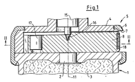
- a bomblet 1 with a transfer charge 2 and an explosive charge 3 carries a housing 4 of a pyrotechnic detonator 5.
- a jacket 6 with an opening 7 for a slide 8 connects the housing 4 to the bomblet 1.
- a firing pin 15 engages securely in a bore 16 of the slide 8.
- a detonator 17 and a sheet 18 with an ignition needle 19 are crimped in the slide 8.
- a delay detonator 25 has:
- the latter is located outside of the response range 32 of the detonator 17, as shown in FIG. 2.
- the tube 26 is slidably mounted in a slide guide 34.
- a ball 35 is mounted in an opening 36 of the slide 8 while the slide 8 is secured.
- the ball 35 is supported on the slide guide 34 and rests on a shoulder 37 of the delay detonator 25.
- the opening 36 is outside the housing 4.
- the slide 8 is provided with a spring 40.
- the slider 8 has a center of gravity 9 at a distance 10 from the main axis 11.
- the bomblet 1 ejected from a swirl projectile also has a corresponding swirl.
- a stabilizing parachute lifts the firing pin 15 out of the bore 16 in a known manner.
- the ball 35 is thrown out of the opening 36 and has thus released the delay detonator 25. This strikes against the sheet 18 due to the inertial forces, whereby the firing needle 19 initiates the ignition charge 29.
- the slide 8 initially only transports the delay detonator 25 until the stop 21 hits the stop 20 of the housing 4 in its movement phase.
- the delay detonator 25 is unlocked.
- the inertial forces act solely on the delay detonator 25 and move it up to the sheet metal 18.
- the transmission set 31 immediately adjacent to the detonator 17 ignites the detonator 17 in accordance with the arrow 44. This then initiates the explosive charge 3 via the transfer charge 2.
- the slide 8 is secured in a known manner.
- the telescopability of the delay detonator allows a relatively large overall length, which is only limited by the run-up section 50 between the firing needle 19 and the primer. In addition, there is also a safety distance, which is defined as the response area 32. Therefore, if the delay detonator 25 is fired in a safe manner outside the rule, it is ensured that the detonator 17 is not initiated due to the spatial separation.
- the hot gases and particles of the transmission set 31 are discharged into relaxation rooms (not shown) of the pyrotechnic igniter 5. Despite the fact that the delay detonator 25 can be telescoped, it is ensured in the focus that the transmission set 31 is in the immediate vicinity of the detonator 17.
- the transmission set 31 penetrates the section 28, the wall 33 and the detonator cup 38.
- a spring 12 effects or supports the arming of the delay detonator 27.
- a slide 68 with the eccentric center of gravity 69 is secured by the firing pin 15 which interacts with the detonator 17 when the bomblet 1 strikes, see FIG. 1.
- the slide 68 is slidably mounted in the housing 4 between guide rails 61.
- the housing 4 has the only opening 7 for the slide 68.
- the following are arranged in the slide 68: the detonator 17, two bores 63, 63 with web 64, a spring-driven firing pin 65, the ignition charge 29 and a U-shaped delay set 70 of a pyrotechnic delay device 60 with plate 71.
- the ball 35 secures the firing pin 65. It rests on the guide 61.
- the guide 61 and the housing 4 are provided with a recess 14.
- the pyrotechnic self-dismantling device is started as follows: The centrifugal forces move the slide 68 into the position 72, which is secured in a known manner.
- the ball 35 falls into the recess 14 and thereby releases the firing pin 65, which ignites the igniter 29. After the predetermined burning time of the delay set 70, the latter ignites the detonator 17. This initiates the explosive charge, not shown, of the bomblet 1.
- the large overall length of the delay set 70 with which relatively extremely long burning times can be realized is advantageous.
- the easy and clear handling of the slide 68 is provided by the integrated structural units, as already described for FIG. 3, namely firing pin 65, pyrotechnic delay device and detonator 17.
- a spring 66 brings the slide 68 into focus, including the firing function of the firing pin 65.
Landscapes
- Engineering & Computer Science (AREA)
- General Engineering & Computer Science (AREA)
- Air Bags (AREA)
Abstract
Bei einem pyrotechnischen Zünder für Geschosse, Bomblets (1) und Minen, wird durch einen teleskopierbaren Verzögerungsdetonator (25) eine verhältnismäßig große Baulänge des Verzögerungsdetonators (25) erreicht. Hierzu ist der Verzögerungsdetonator (25) in einem quer zur Hauptachse (11) des Bomblet (1) verschiebbaren Schieber (8) verschiebbar gelagert und in Sicherstellung des Zünders durch eine Kugelsicherung (34-37) festgelegt. 
Description
Die Erfindung bezieht sich auf einen pyrotechnischen Zünder für Geschosse nach dem Oberbegriff des Anspruches 1.The invention relates to a pyrotechnic detonator for projectiles according to the preamble of
Bei einem Zünder für Bomblets nach der DE 33 33 312 in einem querbeweglichen Schieber ein Detonator und ein Anzündsatz für einen gehäusefesten, spiralförmig angeordneten Verzögerungssatz vorgesehen.
Es ist erkannt worden, daß bei spiralförmig verlaufenden Verzögerungssätzen Funktionsstörungen auftreten können, bspw. die Brennfront des pyrotechnischen Satzes endet vorzeitig. Um diesen Nachteil zu überwinden, setzt man geradlinige bzw. gestreckte Brennsätze ein. Nachteilig daran ist bei quer zur Hauptachse der Munition angeordneten Verzögerungssätzen die relativ kurze Baulänge. Die Baulänge des Brennsatzes ist vom Munitionskaliber abhängig.In a detonator for bomblets according to DE 33 33 312, a detonator and a primer for a housing-fixed, spirally arranged retardation are provided in a transverse slide.
It has been recognized that, in the case of spiraling delay blocks, malfunctions can occur, for example the firing front of the pyrotechnic block ends prematurely. In order to overcome this disadvantage, straight or straight fuel sets are used. A disadvantage of this is the relatively short overall length in the case of delay sets arranged transversely to the main axis of the ammunition. The length of the fuel set depends on the ammunition caliber.
Der Erfindung liegt daher die Aufgabe zugrunde, einem pyrotechnischen Zünder vorzuschlagen, der eine möglichst große Baulänge des Verzögerungssatzes bei sicherer Zündung des Detonators erlaubt.The invention is therefore based on the object of proposing a pyrotechnic detonator which allows the greatest possible length of the delay set with reliable detonator ignition.
Diese Aufgabe wird entsprechend den kennzeichnenden Merkmalen des Anspruches 1 gelöst.
Vorteilhafte Weiterbildungen der Erfindung gehen aus den Unteransprüchen hervor.This object is achieved in accordance with the characterizing features of
Advantageous developments of the invention emerge from the subclaims.
Die Vorteile der Erfindung werden anhand eines in der Zeichnung dargestellten Ausführungsbeispieles erläutert.The advantages of the invention are explained with reference to an embodiment shown in the drawing.
Es zeigt:
- Fig. 1 einen Ausschnitt aus einem pyrotechnischen Zünder für ein Bomblet;
- Fig. 2 einen Schnitt II-II nach Fig. 1;
- Fig. 3 den Zünder nach Fig. 2 in Scharfstellung;
- Fig. 4 einen Querschnitt eines weiteren Zünders.
- Figure 1 shows a section of a pyrotechnic igniter for a bomblet.
- Fig. 2 shows a section II-II of Fig. 1;
- Fig. 3 shows the igniter of Figure 2 in focus.
- Fig. 4 shows a cross section of another igniter.
Ein Bomblet 1 mit einer Übertragungsladung 2 und einer Sprengladung 3 trägt ein Gehäuse 4 eines pyrotechnischen Zünders 5. Ein Mantel 6 mit einer Öffnung 7 für einen Schieber 8 verbindet das Gehäuse 4 mit dem Bomblet 1.A
Ein Schlagbolzen 15 greift in Sicherstellung in eine Bohrung 16 des Schiebers 8 ein. Ein Detonator 17 und ein Blech 18 mit einer Zündnadel 19 sind im Schieber 8 eingebördelt.A
Ein Verzögerungsdetonator 25 weist auf:A
Ein Röhrchen 26 mit den Abschnitten 27 und 28, einen Anzündsatz 29, einen Verzögerungssatz 30 und einen Übertragungssatz 31. Der Letztere liegt in Sicherstellung nach Fig. 2 außerhalb des Ansprechsbereiches 32 des Detonators 17.A
Das Röhrchen 26 ist in einer Schieberführung 34 verschiebbar gelagert. Eine Kugel 35 ist in Sicherstellung des Schiebers 8 in einer Öffnung 36 des Schiebers 8 gelagert. Die Kugel 35 ist an der Schieberführung 34 abgestützt und liegt an einer Schulter 37 des Verzögerungsdetonators 25 an. In Scharfstellung des Schiebers 8 ist die Öffnung 36 außerhalb des Gehäuses 4. Der Schieber 8 ist mit einer Feder 40 versehen.The
Der Schieber 8 weist einen Schwerpunkt 9 in einem Abstand 10 von der Hauptachse 11 auf.The
Das aus einem Drallgeschoß ausgestossene Bomblet 1 weist ebenfalls einen entsprechenden Drall auf. Ein Stabilisierungsfallschirm hebt in bekannter Weise den Schlagbolzen 15 aus der Bohrung 16. Danach bewegen die durch den Drall erzeugten, am Schieber 8 wirksamen Zentrifugalkräfte, unterstützt durch die Feder 40, den Schieber 8 in die aus Fig. 3 ersichtliche Scharfstellung. Sobald die Öffnung 36 außerhalb des Mantels 6 liegt, wird die Kugel 35 aus der Öffnung 36 herausgeschleudert und hat damit den Verzögerungsdetonator 25 freigegeben. Dieser schlägt aufgrund der Massenkräfte gegen das Blech 18, wodurch die Zündnadel 19 den Anzündsatz 29 initiiert. Wesentlich ist, daß der Schieber 8 in seiner Bewegungsphase den Verzögerungsdetonator 25 bis zum Aufschlag des Anschlags 21 an dem Anschlag 20 des Gehäuses 4 zunächst nur transportiert. Dabei wird der Verzögerungsdetonator 25 entsichert. Durch den Aufschlag wirken die Massenkräfte allein an dem Verzögerungsdetonator 25 und bewegen diesen bis an das Blech 18. Nach Ablauf der Brennzeit des Verzögerungssatzes 30 zündet der, dem Detonator 17 unmittelbar benachbarte Übertragungssatz 31 den Detonator 17 entsprechend dem Pfeil 44. Dieser initiiert dann die Sprengladung 3 über die Übertragungsladung 2. In Scharfstellung (Fig. 3) ist der Schieber 8 in bekannter Weise gesichert.The
Der beschriebene Funktionsablauf erfolgt nur unter der Voraussetzung, daß das Bomblet 1 auf weichen Untergrund aufschlägt, so daß für den Schlagbolzen 15 kein entsprechender Impuls vorlag.The functional sequence described takes place only on the condition that the
Die Teleskopierbarkeit des Verzögerungsdetonators erlaubt eine relativ große Baulänge, die nur durch die Anlaufstrecke 50 zwischen der Zündnadel 19 und dem Anzündsatz begrenzt ist. Außerdem liegt in Sicherstellung ein ebenfalls der Sicherheit dienender Abstand vor, der als Ansprechbereich 32 definiert ist. Wird daher außerhalb der Regel der Verzögerungsdetonator 25 in Sicherstellung gezündet, so ist gewährleistet, daß der Detonator 17 aufgrund der räumlichen Trennung nicht initiiert wird.The telescopability of the delay detonator allows a relatively large overall length, which is only limited by the run-up section 50 between the
Die heißen Gase und Partikel des Übertragungssatzes 31 werden in nicht gezeigte Entspannungsräume des pyrotechnischen Zünders 5 abgeleitet.
Trotz der Teleskopierbarkeit des Verzögerungsdetonators 25 ist in Scharfstellung gewährleistet, daß der Übertragungssatz 31 in unmittelbarer Nachbarschaft des Detonators 17 steht. Der Übertragungssatz 31 durchschlägt den Abschnitt 28, die Wand 33 und den Detonatorbecher 38.The hot gases and particles of the transmission set 31 are discharged into relaxation rooms (not shown) of the
Despite the fact that the
Bei einem Bomblet ohne Drall bewirkt bzw. unterstützt eine Feder 12 die Scharfstellung des Verzögerungsdetonators 27.In the case of a bomblet without swirl, a
Nach Fig. 4 ist ein Schieber 68 mit dem exzentrischen Schwerpunkt 69 in Sicherstellung durch den bei Aufschlag des Bomblets 1 mit dem Detonator 17 zusammenwirkenden Schlagbolzen 15 festgelegt, siehe Fig. 1.
Der Schieber 68 ist in dem Gehäuse 4 zwischen Führungsschienen 61 verschiebbar gelagert. Das Gehäuse 4 weist für den Schieber 68 die einzige Öffnung 7 auf.
Im Schieber 68 sind angeordnet:
der Detonator 17, zwei Bohrungen 63,63 mit Steg 64, ein federgetriebener Schlagbolzen 65, der Anzündsatz 29 und ein U-förmiger Verzögerungssatz 70 einer pyrotechnischen Verzögerungseinrichtung 60 mit Platte 71.According to FIG. 4, a
The
The following are arranged in the slide 68:
the
Die Kugel 35 sichert den Schlagbolzen 65. Sie liegt an der Führung 61 an. Die Führung 61 und das Gehäuse 4 sind mit einer Ausnehmung 14 versehen.The
Wenn das einen Drall aufweisende Bomblet 1 im Freiflug ist und der Schlagbolzen 15 zurückgezogen ist, wird die pyrotechnische Selbstzerlegungseinrichtung wie folgt in Gang gesetzt:
Die Fliehkräfte bewegen den Schieber 68 in die in bekannter Weise gesicherte Position 72.When the
The centrifugal forces move the
Die Kugel 35 fällt in die Ausnehmung 14 ein und gibt dadurch den Schlagbolzen 65 frei, der den Anzündsatz 29 zündet. Nach der vorgegebenen Brennzeit des Verzögerungssatzes 70 zündet dieser den Detonator 17. Dieser initiiert die nicht dargestellte Sprengladung des Bomblets 1.The
Vorteilhaft ist die große Baulänge des Verzögerungssatzes 70 mit dem verhältnismäßig extrem lange Brennzeiten zu realisieren sind. Die leichte und übersichtliche Handhabbarkeit des Schiebers 68 ist durch die wie bereits zu Fig. 3 beschriebenen integrierten Baueinheiten, nämlich Schlagbolzen 65, pyrotechnische Verzögerungseinrichtung und Detonator 17, gegeben.The large overall length of the delay set 70 with which relatively extremely long burning times can be realized is advantageous. The easy and clear handling of the
Bei einem Bomblet ohne Drall bewirkt eine Feder 66 die Scharfstellung des Schiebers 68 inklusive der Zündfunktion des Schlagbolzens 65.In a bomblet without swirl, a
Claims (8)
dadurch gekennzeichnet,
daß das Gehäuse (4) eine seitliche Öffnung (7) für den über die äußere Gehäusekontur (Mantel 6) ausfahrbaren, die Verzögerungseinrichtung(25; 60) enthaltenden Schieber (8;68) aufweist.1. Pyrotechnic self-dismantling device for projectiles, missiles, bomblets and mines, which has in a housing an ignition device for a pyrotechnic delay device, consisting of an ignition kit and a delay kit, a detonator for igniting an explosive charge and a firing pin for the detonator, the detonator in a transverse slide is arranged,
characterized,
that the housing (4) has a lateral opening (7) for the slide (8; 68) which can be extended via the outer housing contour (casing 6) and contains the delay device (25; 60).
dadurch gekennzeichnet,
daß die Verzögerungseinrichtung (25) in dem Schieber (8) längsbeweglich verschiebbar gelagert ist,
die Verzögerungseinrichtung (25) über eine Sicherung (34-37) im Schieber (8) festgelegt ist und erst in Scharfstellung des Schiebers (8) entriegelt ist und
daß der Schieber (8) eine ortsfeste Zündnadel (19) für die verschiebbare Verzögerungseinrichtung (25) aufweist.2. Pyrotechnic self-destruct igniter according to claim 1,
characterized,
that the delay device (25) is mounted in the slide (8) so that it can move longitudinally,
the delay device (25) is fixed in the slide (8) via a fuse (34-37) and is only unlocked when the slide (8) is in the armed position and
that the slide (8) has a fixed firing pin (19) for the displaceable delay device (25).
dadurch gekennzeichnet,
daß die Sicherung der Verzögerungseinrichtung (25) eine Kugelsicherung ist, wobei die Kugel (35) in Sicherstellung des Schiebers (8) in einer Öffnung (36) des Schiebers (8) gelagert ist und den Schieber (8) über eine Schieberführung (34) und eine Schulter (37) abgestützt ist, während die Öffnung (36) nahe dem Mantel (6) liegt.3. A pyrotechnic self-igniter according to claim 1,
characterized,
that the safety device of the delay device (25) is a ball safety device, the ball (35) being mounted in an opening (36) of the slide valve (8) while securing the slide valve (8) and the slide valve (8) via a slide guide (34) and a shoulder (37) is supported while the opening (36) is close to the jacket (6).
dadurch gekennzeichnet,
daß in einem Röhrchen (26) ein Übertragungssatz (31), ein Verzögerungssatz (30) und ein detonativer Anzündsatz (29) angeordnet sind, wobei der Übertragungssatz (31) in Sicherstellung außerhalb des Ansprechbereiches (33) des Detonators (17) liegt.4. A pyrotechnic self-igniter according to claim 1,
characterized,
that a transmission set (31), a delay set (30) and a detonative ignition set (29) are arranged in a tube (26), the transmission set (31) being outside the response range (33) of the detonator (17).
dadurch gekennzeichnet,
daß der Schieber (68) in seiner Bewegungsebene zwei zueinander parallele, an nur einem Ende des Schiebers (68) miteinander U-förmig verbundene Bohrungen (62,63) aufweist, die die Anzündvorrichtung (35,36;65) und die pyrotechnische Verzögerungsseinrichtung (29;70) aufweisen.5. A pyrotechnic self-igniter according to claim 1,
characterized,
that the slide (68) has in its plane of movement two mutually parallel bores (62, 63) connected to one another in a U-shape at only one end of the slide (68), which bores the ignition device (35, 36; 65) and the pyrotechnic delay device ( 29; 70).
dadurch gekennzeichnet,
daß der pyrotechnische Verzögerungssatz (70) U-förmig ausgebildet ist und an seinem freien Ende an dem in dem Schieber (68) etwa stirnseitig angeordneten Detonator (17) anliegt.6. A pyrotechnic self-destruct igniter according to claim 5,
characterized,
that the pyrotechnic delay set (70) is U-shaped and rests at its free end on the detonator (17) arranged approximately at the end in the slide (68).
dadurch gekennzeichnet,
daß der Schieber (8,68) durch Federkraft (40) oder durch Fliehkräfte in an sich bekannter Weise in Sicherstellung durch einen in der Hauptachse des Zünders gelagerten Schlagbolzen (15) formschlüssig festgelegt ist und der Schieber (8;68) nach dessen Entriegelung aus der Sicherstellung in die Scharfstellung (72) bewegbar ist.7. A pyrotechnic self-igniter according to claim 1,
characterized,
that the slide (8,68) by spring force (40) or by centrifugal forces in a manner known per se is secured by a firing pin (15) mounted in the main axis of the detonator and the slide (8; 68) after it is unlocked ensuring that the arming (72) can be moved.
dadurch gekennzeichnet,
daß in der Scharfstellung des Schiebers (8) die Anschläge (20,21) aneinander anliegen.8. A pyrotechnic self-igniter according to claim 2,
characterized,
that when the slide (8) is in focus, the stops (20, 21) lie against one another.
Applications Claiming Priority (2)
| Application Number | Priority Date | Filing Date | Title |
|---|---|---|---|
| DE19873740967 DE3740967A1 (en) | 1987-12-03 | 1987-12-03 | PYROTECHNICAL IGNITION FOR BULLETS |
| DE3740967 | 1987-12-03 |
Publications (3)
| Publication Number | Publication Date |
|---|---|
| EP0318995A2 true EP0318995A2 (en) | 1989-06-07 |
| EP0318995A3 EP0318995A3 (en) | 1990-04-18 |
| EP0318995B1 EP0318995B1 (en) | 1994-05-18 |
Family
ID=6341802
Family Applications (1)
| Application Number | Title | Priority Date | Filing Date |
|---|---|---|---|
| EP88120077A Expired - Lifetime EP0318995B1 (en) | 1987-12-03 | 1988-12-01 | Pyrotechnical initiator for projectiles |
Country Status (3)
| Country | Link |
|---|---|
| US (1) | US4901643A (en) |
| EP (1) | EP0318995B1 (en) |
| DE (2) | DE3740967A1 (en) |
Cited By (7)
| Publication number | Priority date | Publication date | Assignee | Title |
|---|---|---|---|---|
| EP0411243A1 (en) * | 1989-07-29 | 1991-02-06 | Rheinmetall GmbH | Fuse for a bomblet |
| EP0666464A1 (en) * | 1994-01-31 | 1995-08-09 | Oregon Etablissement Für Patentverwertung | Fuse for a grenade |
| US5670736A (en) * | 1995-07-27 | 1997-09-23 | Giat Industries | Priming system for the explosive charge of a submunition on board a carrier |
| EP1048923A1 (en) * | 1999-04-27 | 2000-11-02 | Junghans Feinwerktechnik GmbH & Co.KG | Pyrotechnic fuze for the self-destruction of an ammunition |
| FR2795814A1 (en) * | 1999-06-30 | 2001-01-05 | Rheinmetall W & M Gmbh | Safety system for detonator has pyrotechnic retarding agent actuated by hot gases when propulsion powder is burned and releases locating pin attached to a transmission support which can then take armed position |
| EP2645049A3 (en) * | 2012-03-30 | 2015-10-14 | Diehl BGT Defence GmbH & Co.KG | Device for igniting a pyrotechnic material |
| EP3076122A1 (en) * | 2015-04-01 | 2016-10-05 | Inauen-Schätti AG | System for triggering of avalanches |
Families Citing this family (6)
| Publication number | Priority date | Publication date | Assignee | Title |
|---|---|---|---|---|
| DE3912671A1 (en) * | 1989-04-18 | 1990-10-25 | Diehl Gmbh & Co | IGNITION OF A BOMBLET |
| DE4303128C2 (en) * | 1993-02-04 | 1995-10-12 | Rheinmetall Ind Gmbh | Projectile device for projectiles, missiles, bomblets and mines with a pyrotechnic self-dismantling device |
| DE9419261U1 (en) * | 1994-12-01 | 1996-04-04 | Gebrüder Junghans GmbH, 78713 Schramberg | Impact detonator for ammunition |
| DE19726951C2 (en) * | 1997-06-25 | 1999-12-16 | Rheinmetall W & M Gmbh | Detonator for a swirl projectile with a self-dismantling unit arranged in the locking bolt for the detonator carrier |
| ES2174661B1 (en) * | 1999-02-22 | 2004-08-16 | Instalaza, S.A. | IMPROVEMENTS INTRODUCED IN SELF-DESTRUCTIVE ELECTRONIC SPOOLS. |
| CN109654961B (en) * | 2018-12-10 | 2021-10-01 | 中国航天科工集团八五一一研究所 | Safe ignition device capable of effectively preventing chamber from being blocked |
Family Cites Families (14)
| Publication number | Priority date | Publication date | Assignee | Title |
|---|---|---|---|---|
| GB529505A (en) * | 1938-02-17 | 1940-11-22 | Bofors Ab | Percussion fuzes for aerial bombs |
| GB624135A (en) * | 1945-02-02 | 1949-05-27 | Controles Ind Et | Improvements in and relating to detonating devices for rocket projectiles |
| US3025795A (en) * | 1958-02-12 | 1962-03-20 | Thiokol Chemical Corp | Time delay fuse element |
| CH456403A (en) * | 1966-07-28 | 1968-07-31 | Tamerlan Ets | Percussion fuze for projectile |
| CH448812A (en) * | 1967-03-10 | 1967-12-15 | Fibora Ag | Mine detonator with detonator fuse |
| US4030418A (en) * | 1975-10-30 | 1977-06-21 | The United States Of America As Represented By The Secretary Of The Army | Gravity deployed mine with combined upper clearing charge firing and delayed main charge initiation |
| US4029016A (en) * | 1976-06-29 | 1977-06-14 | The United States Of America As Represented By The Secretary Of The Army | Plural mode fuze |
| DE3333312A1 (en) * | 1983-09-15 | 1985-04-04 | Rheinmetall GmbH, 4000 Düsseldorf | IGNITION FOR A SUBFLOOR |
| CA1225542A (en) * | 1984-12-03 | 1987-08-18 | Gilles M. Berube | Firing pin and safety and arming mechanism for a penetrating warhead |
| DE3539279A1 (en) * | 1985-11-06 | 1987-05-07 | Diehl Gmbh & Co | Detonator for a parachute-stabilised or strip-stabilised submunition |
| FR2592475B1 (en) * | 1985-12-27 | 1989-11-03 | Lacroix E Tous Artifices | PYROTECHNICALLY ACTUATED LOAD AND AMMUNITION INCORPORATING THE SAME. |
| DE8614108U1 (en) * | 1986-05-24 | 1987-09-24 | Diehl GmbH & Co, 8500 Nürnberg | Impact fuse of an infantry grenade |
| DE3624713C2 (en) * | 1986-07-22 | 1995-09-07 | Diehl Gmbh & Co | Impact detonator with self-dismantling device for a bomblet |
| IL82066A (en) * | 1987-03-31 | 1992-03-29 | Israel State | Fuse for sub-munition warhead |
-
1987
- 1987-12-03 DE DE19873740967 patent/DE3740967A1/en not_active Withdrawn
-
1988
- 1988-11-29 US US07/277,275 patent/US4901643A/en not_active Expired - Fee Related
- 1988-12-01 DE DE3889636T patent/DE3889636D1/en not_active Expired - Fee Related
- 1988-12-01 EP EP88120077A patent/EP0318995B1/en not_active Expired - Lifetime
Cited By (8)
| Publication number | Priority date | Publication date | Assignee | Title |
|---|---|---|---|---|
| EP0411243A1 (en) * | 1989-07-29 | 1991-02-06 | Rheinmetall GmbH | Fuse for a bomblet |
| US5048419A (en) * | 1989-07-29 | 1991-09-17 | Rheinmetall Gmbh | Bomblet fuze |
| EP0666464A1 (en) * | 1994-01-31 | 1995-08-09 | Oregon Etablissement Für Patentverwertung | Fuse for a grenade |
| US5670736A (en) * | 1995-07-27 | 1997-09-23 | Giat Industries | Priming system for the explosive charge of a submunition on board a carrier |
| EP1048923A1 (en) * | 1999-04-27 | 2000-11-02 | Junghans Feinwerktechnik GmbH & Co.KG | Pyrotechnic fuze for the self-destruction of an ammunition |
| FR2795814A1 (en) * | 1999-06-30 | 2001-01-05 | Rheinmetall W & M Gmbh | Safety system for detonator has pyrotechnic retarding agent actuated by hot gases when propulsion powder is burned and releases locating pin attached to a transmission support which can then take armed position |
| EP2645049A3 (en) * | 2012-03-30 | 2015-10-14 | Diehl BGT Defence GmbH & Co.KG | Device for igniting a pyrotechnic material |
| EP3076122A1 (en) * | 2015-04-01 | 2016-10-05 | Inauen-Schätti AG | System for triggering of avalanches |
Also Published As
| Publication number | Publication date |
|---|---|
| EP0318995A3 (en) | 1990-04-18 |
| DE3740967A1 (en) | 1989-06-15 |
| US4901643A (en) | 1990-02-20 |
| DE3889636D1 (en) | 1994-06-23 |
| EP0318995B1 (en) | 1994-05-18 |
Similar Documents
| Publication | Publication Date | Title |
|---|---|---|
| DE3624713A1 (en) | IGNITION FOR A PARACHUTE OR TAPE-STABILIZED BOMBLET ROTATING IN FLIGHT | |
| EP0318995A2 (en) | Pyrotechnical initiator for projectiles | |
| DE19983923B4 (en) | Self-destructive impact detonator | |
| DE1578457B2 (en) | SAFETY DEVICE FOR IMPACT DETECTOR | |
| EP0318996B1 (en) | Pyrotechnical initiator for projectiles, rockets, bomblets and mines | |
| DE912064C (en) | Mechanical dismantling ignition | |
| EP1170570A2 (en) | Safety for a pyrotechnically activated impact fuze for a projectile | |
| EP0318997B1 (en) | Safety device for a pyrotechnical self-destruction fuze for use with bomblets | |
| EP0104138B1 (en) | Device for arming and sterilising an electric fuze for ammunition | |
| DE4303128A1 (en) | Fuze device for projectiles, rockets, bomblets and mines having a pyrotechnic self-destruction device | |
| EP0499701B1 (en) | Safety device for barrel launched projectiles | |
| EP0218947B1 (en) | Impact fuze having a detonator cap | |
| EP0236325B1 (en) | Self-destroying igniter | |
| DE4127023A1 (en) | Missile propellant charge igniter - has spring-loaded firing pin functioning at predetermined time after the missile is fired | |
| CH656001A5 (en) | IGNITION AND BULLET WITH ONE IGNITION. | |
| DE1428801A1 (en) | Igniter | |
| DE2426168C3 (en) | Micro-timed rocket detonators | |
| DE2310668A1 (en) | PUNCHER | |
| DE1147516B (en) | Hand grenade detonator | |
| WO2000055570A1 (en) | Safety and time-delay circuit for a percussion fuse | |
| DE207803C (en) | ||
| EP1048922B1 (en) | Fuze for the self-destruction of the ammunition | |
| DE2941311A1 (en) | HIT HEAD FOR AN EXPLOSIVE BULLET | |
| DE60312243T2 (en) | Explosive projectile and method for neutralizing this projectile | |
| DE224371C (en) |
Legal Events
| Date | Code | Title | Description |
|---|---|---|---|
| PUAI | Public reference made under article 153(3) epc to a published international application that has entered the european phase |
Free format text: ORIGINAL CODE: 0009012 |
|
| AK | Designated contracting states |
Kind code of ref document: A2 Designated state(s): DE FR GB IT |
|
| PUAL | Search report despatched |
Free format text: ORIGINAL CODE: 0009013 |
|
| AK | Designated contracting states |
Kind code of ref document: A3 Designated state(s): DE FR GB IT |
|
| 17P | Request for examination filed |
Effective date: 19900310 |
|
| 17Q | First examination report despatched |
Effective date: 19911111 |
|
| RBV | Designated contracting states (corrected) |
Designated state(s): DE |
|
| GRAA | (expected) grant |
Free format text: ORIGINAL CODE: 0009210 |
|
| AK | Designated contracting states |
Kind code of ref document: B1 Designated state(s): DE |
|
| REF | Corresponds to: |
Ref document number: 3889636 Country of ref document: DE Date of ref document: 19940623 |
|
| PLBE | No opposition filed within time limit |
Free format text: ORIGINAL CODE: 0009261 |
|
| STAA | Information on the status of an ep patent application or granted ep patent |
Free format text: STATUS: NO OPPOSITION FILED WITHIN TIME LIMIT |
|
| 26N | No opposition filed | ||
| PGFP | Annual fee paid to national office [announced via postgrant information from national office to epo] |
Ref country code: DE Payment date: 20010221 Year of fee payment: 13 |
|
| PG25 | Lapsed in a contracting state [announced via postgrant information from national office to epo] |
Ref country code: DE Free format text: LAPSE BECAUSE OF NON-PAYMENT OF DUE FEES Effective date: 20020702 |