EP0318995A2 - Allumeur pyrotechnique pour projectiles - Google Patents
Allumeur pyrotechnique pour projectiles Download PDFInfo
- Publication number
- EP0318995A2 EP0318995A2 EP88120077A EP88120077A EP0318995A2 EP 0318995 A2 EP0318995 A2 EP 0318995A2 EP 88120077 A EP88120077 A EP 88120077A EP 88120077 A EP88120077 A EP 88120077A EP 0318995 A2 EP0318995 A2 EP 0318995A2
- Authority
- EP
- European Patent Office
- Prior art keywords
- slide
- detonator
- pyrotechnic
- delay
- igniter according
- Prior art date
- Legal status (The legal status is an assumption and is not a legal conclusion. Google has not performed a legal analysis and makes no representation as to the accuracy of the status listed.)
- Granted
Links
- 239000003999 initiator Substances 0.000 title 1
- 238000010304 firing Methods 0.000 claims description 18
- 230000005540 biological transmission Effects 0.000 claims description 7
- 239000002360 explosive Substances 0.000 claims description 4
- 239000000446 fuel Substances 0.000 description 2
- 230000005484 gravity Effects 0.000 description 2
- 238000011161 development Methods 0.000 description 1
- 230000018109 developmental process Effects 0.000 description 1
- 230000000694 effects Effects 0.000 description 1
- 239000007789 gas Substances 0.000 description 1
- 230000007257 malfunction Effects 0.000 description 1
- 239000002184 metal Substances 0.000 description 1
- 239000002245 particle Substances 0.000 description 1
- 238000000926 separation method Methods 0.000 description 1
- 230000000087 stabilizing effect Effects 0.000 description 1
- 230000032258 transport Effects 0.000 description 1
Images


Classifications
-
- F—MECHANICAL ENGINEERING; LIGHTING; HEATING; WEAPONS; BLASTING
- F42—AMMUNITION; BLASTING
- F42C—AMMUNITION FUZES; ARMING OR SAFETY MEANS THEREFOR
- F42C9/00—Time fuzes; Combined time and percussion or pressure-actuated fuzes; Fuzes for timed self-destruction of ammunition
- F42C9/14—Double fuzes; Multiple fuzes
- F42C9/142—Double fuzes; Multiple fuzes combined time and percussion fuzes in which the timing is caused by combustion
-
- F—MECHANICAL ENGINEERING; LIGHTING; HEATING; WEAPONS; BLASTING
- F42—AMMUNITION; BLASTING
- F42C—AMMUNITION FUZES; ARMING OR SAFETY MEANS THEREFOR
- F42C15/00—Arming-means in fuzes; Safety means for preventing premature detonation of fuzes or charges
- F42C15/18—Arming-means in fuzes; Safety means for preventing premature detonation of fuzes or charges wherein a carrier for an element of the pyrotechnic or explosive train is moved
- F42C15/184—Arming-means in fuzes; Safety means for preventing premature detonation of fuzes or charges wherein a carrier for an element of the pyrotechnic or explosive train is moved using a slidable carrier
Definitions
- the invention relates to a pyrotechnic detonator for projectiles according to the preamble of claim 1.
- a detonator and a primer for a housing-fixed, spirally arranged retardation are provided in a transverse slide. It has been recognized that, in the case of spiraling delay blocks, malfunctions can occur, for example the firing front of the pyrotechnic block ends prematurely. In order to overcome this disadvantage, straight or straight fuel sets are used. A disadvantage of this is the relatively short overall length in the case of delay sets arranged transversely to the main axis of the ammunition. The length of the fuel set depends on the ammunition caliber.
- the invention is therefore based on the object of proposing a pyrotechnic detonator which allows the greatest possible length of the delay set with reliable detonator ignition.
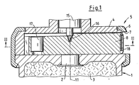
- a bomblet 1 with a transfer charge 2 and an explosive charge 3 carries a housing 4 of a pyrotechnic detonator 5.
- a jacket 6 with an opening 7 for a slide 8 connects the housing 4 to the bomblet 1.
- a firing pin 15 engages securely in a bore 16 of the slide 8.
- a detonator 17 and a sheet 18 with an ignition needle 19 are crimped in the slide 8.
- a delay detonator 25 has:
- the latter is located outside of the response range 32 of the detonator 17, as shown in FIG. 2.
- the tube 26 is slidably mounted in a slide guide 34.
- a ball 35 is mounted in an opening 36 of the slide 8 while the slide 8 is secured.
- the ball 35 is supported on the slide guide 34 and rests on a shoulder 37 of the delay detonator 25.
- the opening 36 is outside the housing 4.
- the slide 8 is provided with a spring 40.
- the slider 8 has a center of gravity 9 at a distance 10 from the main axis 11.
- the bomblet 1 ejected from a swirl projectile also has a corresponding swirl.
- a stabilizing parachute lifts the firing pin 15 out of the bore 16 in a known manner.
- the ball 35 is thrown out of the opening 36 and has thus released the delay detonator 25. This strikes against the sheet 18 due to the inertial forces, whereby the firing needle 19 initiates the ignition charge 29.
- the slide 8 initially only transports the delay detonator 25 until the stop 21 hits the stop 20 of the housing 4 in its movement phase.
- the delay detonator 25 is unlocked.
- the inertial forces act solely on the delay detonator 25 and move it up to the sheet metal 18.
- the transmission set 31 immediately adjacent to the detonator 17 ignites the detonator 17 in accordance with the arrow 44. This then initiates the explosive charge 3 via the transfer charge 2.
- the slide 8 is secured in a known manner.
- the telescopability of the delay detonator allows a relatively large overall length, which is only limited by the run-up section 50 between the firing needle 19 and the primer. In addition, there is also a safety distance, which is defined as the response area 32. Therefore, if the delay detonator 25 is fired in a safe manner outside the rule, it is ensured that the detonator 17 is not initiated due to the spatial separation.
- the hot gases and particles of the transmission set 31 are discharged into relaxation rooms (not shown) of the pyrotechnic igniter 5. Despite the fact that the delay detonator 25 can be telescoped, it is ensured in the focus that the transmission set 31 is in the immediate vicinity of the detonator 17.
- the transmission set 31 penetrates the section 28, the wall 33 and the detonator cup 38.
- a spring 12 effects or supports the arming of the delay detonator 27.
- a slide 68 with the eccentric center of gravity 69 is secured by the firing pin 15 which interacts with the detonator 17 when the bomblet 1 strikes, see FIG. 1.
- the slide 68 is slidably mounted in the housing 4 between guide rails 61.
- the housing 4 has the only opening 7 for the slide 68.
- the following are arranged in the slide 68: the detonator 17, two bores 63, 63 with web 64, a spring-driven firing pin 65, the ignition charge 29 and a U-shaped delay set 70 of a pyrotechnic delay device 60 with plate 71.
- the ball 35 secures the firing pin 65. It rests on the guide 61.
- the guide 61 and the housing 4 are provided with a recess 14.
- the pyrotechnic self-dismantling device is started as follows: The centrifugal forces move the slide 68 into the position 72, which is secured in a known manner.
- the ball 35 falls into the recess 14 and thereby releases the firing pin 65, which ignites the igniter 29. After the predetermined burning time of the delay set 70, the latter ignites the detonator 17. This initiates the explosive charge, not shown, of the bomblet 1.
- the large overall length of the delay set 70 with which relatively extremely long burning times can be realized is advantageous.
- the easy and clear handling of the slide 68 is provided by the integrated structural units, as already described for FIG. 3, namely firing pin 65, pyrotechnic delay device and detonator 17.
- a spring 66 brings the slide 68 into focus, including the firing function of the firing pin 65.
Landscapes
- Engineering & Computer Science (AREA)
- General Engineering & Computer Science (AREA)
- Air Bags (AREA)
Applications Claiming Priority (2)
| Application Number | Priority Date | Filing Date | Title |
|---|---|---|---|
| DE3740967 | 1987-12-03 | ||
| DE19873740967 DE3740967A1 (de) | 1987-12-03 | 1987-12-03 | Pyrotechnischer zuender fuer geschosse |
Publications (3)
| Publication Number | Publication Date |
|---|---|
| EP0318995A2 true EP0318995A2 (fr) | 1989-06-07 |
| EP0318995A3 EP0318995A3 (en) | 1990-04-18 |
| EP0318995B1 EP0318995B1 (fr) | 1994-05-18 |
Family
ID=6341802
Family Applications (1)
| Application Number | Title | Priority Date | Filing Date |
|---|---|---|---|
| EP88120077A Expired - Lifetime EP0318995B1 (fr) | 1987-12-03 | 1988-12-01 | Allumeur pyrotechnique pour projectiles |
Country Status (3)
| Country | Link |
|---|---|
| US (1) | US4901643A (fr) |
| EP (1) | EP0318995B1 (fr) |
| DE (2) | DE3740967A1 (fr) |
Cited By (7)
| Publication number | Priority date | Publication date | Assignee | Title |
|---|---|---|---|---|
| EP0411243A1 (fr) * | 1989-07-29 | 1991-02-06 | Rheinmetall GmbH | Allumeur pour sous-munition du type "bomblet" |
| EP0666464A1 (fr) * | 1994-01-31 | 1995-08-09 | Oregon Etablissement Für Patentverwertung | Fusée pour grenade |
| US5670736A (en) * | 1995-07-27 | 1997-09-23 | Giat Industries | Priming system for the explosive charge of a submunition on board a carrier |
| EP1048923A1 (fr) * | 1999-04-27 | 2000-11-02 | Junghans Feinwerktechnik GmbH & Co.KG | Fusée pyrotechnique pour l'autodestruction d'une munition |
| FR2795814A1 (fr) * | 1999-06-30 | 2001-01-05 | Rheinmetall W & M Gmbh | Element de surete pour detonateurs d'une munition lancee sans rotation ou seulement avec une rotation tres faible |
| EP2645049A3 (fr) * | 2012-03-30 | 2015-10-14 | Diehl BGT Defence GmbH & Co.KG | Dispositif d'allumage d'une masse pyrotechnique |
| EP3076122A1 (fr) * | 2015-04-01 | 2016-10-05 | Inauen-Schätti AG | Système de déclenchement d'avalanches |
Families Citing this family (6)
| Publication number | Priority date | Publication date | Assignee | Title |
|---|---|---|---|---|
| DE3912671A1 (de) * | 1989-04-18 | 1990-10-25 | Diehl Gmbh & Co | Zuender eines bomblets |
| DE4303128C2 (de) * | 1993-02-04 | 1995-10-12 | Rheinmetall Ind Gmbh | Zündvorrichtung für Geschosse, Raketen, Bomblets und Minen mit einer pyrotechnischen Selbstzerlegervorrichtung |
| DE9419261U1 (de) * | 1994-12-01 | 1996-04-04 | Gebrüder Junghans GmbH, 78713 Schramberg | Aufschlagzünder für Munition |
| DE19726951C2 (de) * | 1997-06-25 | 1999-12-16 | Rheinmetall W & M Gmbh | Zünder für ein Drallgeschoß mit im Verriegelungsbolzen für den Detonatorträger angeordneter Selbstzerlegereinheit |
| ES2174661B1 (es) * | 1999-02-22 | 2004-08-16 | Instalaza, S.A. | Mejoras introducidas en espoletas electronicas auto-destructivas. |
| CN109654961B (zh) * | 2018-12-10 | 2021-10-01 | 中国航天科工集团八五一一研究所 | 一种可有效防卡膛的安全点火装置 |
Family Cites Families (14)
| Publication number | Priority date | Publication date | Assignee | Title |
|---|---|---|---|---|
| GB529505A (en) * | 1938-02-17 | 1940-11-22 | Bofors Ab | Percussion fuzes for aerial bombs |
| GB624135A (en) * | 1945-02-02 | 1949-05-27 | Controles Ind Et | Improvements in and relating to detonating devices for rocket projectiles |
| US3025795A (en) * | 1958-02-12 | 1962-03-20 | Thiokol Chemical Corp | Time delay fuse element |
| CH456403A (fr) * | 1966-07-28 | 1968-07-31 | Tamerlan Ets | Fusée à percussion pour projectile |
| CH448812A (de) * | 1967-03-10 | 1967-12-15 | Fibora Ag | Minenzünder mit Sprengkapselsicherung |
| US4030418A (en) * | 1975-10-30 | 1977-06-21 | The United States Of America As Represented By The Secretary Of The Army | Gravity deployed mine with combined upper clearing charge firing and delayed main charge initiation |
| US4029016A (en) * | 1976-06-29 | 1977-06-14 | The United States Of America As Represented By The Secretary Of The Army | Plural mode fuze |
| DE3333312A1 (de) * | 1983-09-15 | 1985-04-04 | Rheinmetall GmbH, 4000 Düsseldorf | Zuender fuer ein tochtergeschoss |
| CA1225542A (fr) * | 1984-12-03 | 1987-08-18 | Gilles M. Berube | Perculeur, et son mecanisme de surete et d'armement pour ogive percante |
| DE3539279A1 (de) * | 1985-11-06 | 1987-05-07 | Diehl Gmbh & Co | Zuender fuer ein fallschirm- oder bandstabilisiertes bomblet |
| FR2592475B1 (fr) * | 1985-12-27 | 1989-11-03 | Lacroix E Tous Artifices | Charge a actionnement pyrotechnique et munition incorporant celle-ci. |
| DE8614108U1 (de) * | 1986-05-24 | 1987-09-24 | Diehl GmbH & Co, 8500 Nürnberg | Aufschlagzünder einer Infanteriegranate |
| DE3624713C2 (de) * | 1986-07-22 | 1995-09-07 | Diehl Gmbh & Co | Aufschlagzünder mit Selbstzerlegeeinrichtung für einen Bomblet |
| IL82066A (en) * | 1987-03-31 | 1992-03-29 | Israel State | Fuse for sub-munition warhead |
-
1987
- 1987-12-03 DE DE19873740967 patent/DE3740967A1/de not_active Withdrawn
-
1988
- 1988-11-29 US US07/277,275 patent/US4901643A/en not_active Expired - Fee Related
- 1988-12-01 EP EP88120077A patent/EP0318995B1/fr not_active Expired - Lifetime
- 1988-12-01 DE DE3889636T patent/DE3889636D1/de not_active Expired - Fee Related
Cited By (8)
| Publication number | Priority date | Publication date | Assignee | Title |
|---|---|---|---|---|
| EP0411243A1 (fr) * | 1989-07-29 | 1991-02-06 | Rheinmetall GmbH | Allumeur pour sous-munition du type "bomblet" |
| US5048419A (en) * | 1989-07-29 | 1991-09-17 | Rheinmetall Gmbh | Bomblet fuze |
| EP0666464A1 (fr) * | 1994-01-31 | 1995-08-09 | Oregon Etablissement Für Patentverwertung | Fusée pour grenade |
| US5670736A (en) * | 1995-07-27 | 1997-09-23 | Giat Industries | Priming system for the explosive charge of a submunition on board a carrier |
| EP1048923A1 (fr) * | 1999-04-27 | 2000-11-02 | Junghans Feinwerktechnik GmbH & Co.KG | Fusée pyrotechnique pour l'autodestruction d'une munition |
| FR2795814A1 (fr) * | 1999-06-30 | 2001-01-05 | Rheinmetall W & M Gmbh | Element de surete pour detonateurs d'une munition lancee sans rotation ou seulement avec une rotation tres faible |
| EP2645049A3 (fr) * | 2012-03-30 | 2015-10-14 | Diehl BGT Defence GmbH & Co.KG | Dispositif d'allumage d'une masse pyrotechnique |
| EP3076122A1 (fr) * | 2015-04-01 | 2016-10-05 | Inauen-Schätti AG | Système de déclenchement d'avalanches |
Also Published As
| Publication number | Publication date |
|---|---|
| DE3889636D1 (de) | 1994-06-23 |
| EP0318995A3 (en) | 1990-04-18 |
| DE3740967A1 (de) | 1989-06-15 |
| EP0318995B1 (fr) | 1994-05-18 |
| US4901643A (en) | 1990-02-20 |
Similar Documents
| Publication | Publication Date | Title |
|---|---|---|
| DE3624713A1 (de) | Zuender fuer ein fallschirm- oder bandstabilisiertes, im flug rotierendes bomblett | |
| EP0318995A2 (fr) | Allumeur pyrotechnique pour projectiles | |
| DE19983923B4 (de) | Selbstzerstörender Aufprallzünder | |
| DE1578457B2 (de) | Sicherungseinrichtung fuer aufschlagzuender | |
| DE4335022C2 (de) | Zünd- und Sicherungseinrichtung mit Selbstzerlegungseinrichtung für ein mit einer Hohlladungseinlage versehenes Granatengeschoß | |
| EP0318996B1 (fr) | Allumeur pyrotechnique pour projectiles, roquettes bombes et mines | |
| EP1170570A2 (fr) | Sécurité pour une fusée à impact pour projectile, la fusée étant activée par voie pyrotechnique | |
| EP0318997B1 (fr) | Dispositif de sécurité pour une fusée à autodestruction par combustion pour utilisation dans des bombes | |
| EP0104138B1 (fr) | Dispositif pour armer et neutraliser une fusée électrique pour munition | |
| DE4303128A1 (de) | Zündvorrichtung für Geschosse, Raketen, Bomblets und Minen mit einer pyrotechnischen Selbstzerlegervorrichtung | |
| EP0499701B1 (fr) | Dispositif de sécurité pour projectile destiné à être lancé à partir d'un tube | |
| EP0218947B1 (fr) | Fusée d'impact comportant une amorce à percussion | |
| EP0236325B1 (fr) | Detonateur auto-destructeur | |
| DE4127023A1 (de) | Treibladungsanzuender | |
| CH656001A5 (de) | Zuender sowie geschoss mit einem zuender. | |
| DE1428801A1 (de) | Zuender | |
| DE2426168C3 (de) | Mikrozeitzünder für Raketen | |
| DE2310668A1 (de) | Aufschlagzuender | |
| DE1147516B (de) | Handgranatenzuender | |
| WO2000055570A1 (fr) | Circuit de securite et de retardement pour fusee percutante | |
| DE207803C (fr) | ||
| EP1048922B1 (fr) | Fusée pour l'autodestruction d'une munition | |
| DE2941311A1 (de) | Aufschlagzuendkopf fuer ein explosivgeschoss | |
| DE60312243T2 (de) | Explosives Geschoss und Verfahren zum Neutralisieren dieses Geschosses | |
| DE224371C (fr) |
Legal Events
| Date | Code | Title | Description |
|---|---|---|---|
| PUAI | Public reference made under article 153(3) epc to a published international application that has entered the european phase |
Free format text: ORIGINAL CODE: 0009012 |
|
| AK | Designated contracting states |
Kind code of ref document: A2 Designated state(s): DE FR GB IT |
|
| PUAL | Search report despatched |
Free format text: ORIGINAL CODE: 0009013 |
|
| AK | Designated contracting states |
Kind code of ref document: A3 Designated state(s): DE FR GB IT |
|
| 17P | Request for examination filed |
Effective date: 19900310 |
|
| 17Q | First examination report despatched |
Effective date: 19911111 |
|
| RBV | Designated contracting states (corrected) |
Designated state(s): DE |
|
| GRAA | (expected) grant |
Free format text: ORIGINAL CODE: 0009210 |
|
| AK | Designated contracting states |
Kind code of ref document: B1 Designated state(s): DE |
|
| REF | Corresponds to: |
Ref document number: 3889636 Country of ref document: DE Date of ref document: 19940623 |
|
| PLBE | No opposition filed within time limit |
Free format text: ORIGINAL CODE: 0009261 |
|
| STAA | Information on the status of an ep patent application or granted ep patent |
Free format text: STATUS: NO OPPOSITION FILED WITHIN TIME LIMIT |
|
| 26N | No opposition filed | ||
| PGFP | Annual fee paid to national office [announced via postgrant information from national office to epo] |
Ref country code: DE Payment date: 20010221 Year of fee payment: 13 |
|
| PG25 | Lapsed in a contracting state [announced via postgrant information from national office to epo] |
Ref country code: DE Free format text: LAPSE BECAUSE OF NON-PAYMENT OF DUE FEES Effective date: 20020702 |