EP0319078A2 - Procédé et dispositif pour la détermination de début et de fin d'un mot isolé dans un signal de parole - Google Patents
Procédé et dispositif pour la détermination de début et de fin d'un mot isolé dans un signal de parole Download PDFInfo
- Publication number
- EP0319078A2 EP0319078A2 EP88202629A EP88202629A EP0319078A2 EP 0319078 A2 EP0319078 A2 EP 0319078A2 EP 88202629 A EP88202629 A EP 88202629A EP 88202629 A EP88202629 A EP 88202629A EP 0319078 A2 EP0319078 A2 EP 0319078A2
- Authority
- EP
- European Patent Office
- Prior art keywords
- window
- value
- digital values
- signal
- digital
- Prior art date
- Legal status (The legal status is an assumption and is not a legal conclusion. Google has not performed a legal analysis and makes no representation as to the accuracy of the status listed.)
- Withdrawn
Links
Images


Classifications
-
- G—PHYSICS
- G10—MUSICAL INSTRUMENTS; ACOUSTICS
- G10L—SPEECH ANALYSIS TECHNIQUES OR SPEECH SYNTHESIS; SPEECH RECOGNITION; SPEECH OR VOICE PROCESSING TECHNIQUES; SPEECH OR AUDIO CODING OR DECODING
- G10L25/00—Speech or voice analysis techniques not restricted to a single one of groups G10L15/00 - G10L21/00
- G10L25/78—Detection of presence or absence of voice signals
- G10L25/87—Detection of discrete points within a voice signal
Definitions
- the invention relates to a method for determining the starting point and end point of a word signal corresponding to an isolated spoken word in a speech signal by determining an extreme value in a sequence of digital values derived from the speech signal, taking into account values of the signal curve surrounding the extreme value and a threshold value.
- Such methods for determining the start and end point in a speech signal are used in particular if the speech signal consists of words spoken in isolation or very short word groups and these words or word groups are to be recognized automatically.
- the actual word signal is accompanied by interference and noise and pauses as well as by background noise such as loud inhalation.
- background noise such as loud inhalation.
- the object of the invention is therefore to provide a method of the type mentioned at the outset which enables the most reliable possible determination of the start and end point even in the case of speech signals which are overlaid by essential interference signals.
- a number of previously successively arriving digital values are assigned to three adjacent windows, of which the first window (end window) a predetermined first number of the last arrived digital values, the second window (signal window) one between a predetermined first value and a predetermined larger second value varying second number of digital values and the third window (initial window) comprises a predetermined third number of digital values that for each new digital value from the digital values in the first window and successively for each value of the second number from the digital values of the associated third window a threshold is formed by which each digital value of the second window is reduced, that the sum of the digital values thus reduced for each value of the second Number compared with a highest sum previously formed in the same way and, depending on the comparison result, is stored as a new highest sum together with position information about the position of the second window within the sequence of the digital values, and that the position information last saved indicate the starting point and the end point of the word signal .
- the determination of the start and end points takes place continuously with the arrival of the speech signal, so that for each at least provisionally optimal determination of the end points, the recognition of the speech signal can begin, which is terminated when a more favorable value for the end points is found, so that faster detection is also possible.
- the threshold value that is used in the determination of the end points should originate as much as possible from the interference signal, the size of which is not, however, readily known. This is done according to the invention by taking into account a respective area before and after the assumed position of the word signal.
- This threshold value can be formed particularly easily by forming the threshold value from the sum of the digital values in the first and third window and a correction value. Such a sum formation can be carried out very easily and quickly.
- a fixed value can be selected as the correction value, which takes into account, for example, a general quality of the speech signal.
- this correction value further takes into account the course of the speech signal, is characterized in that for each new digital value at the smallest value of the second number, the sum of the digital values of the second window is formed and stored if a previously stored second window sum is smaller, and the sum of the digital values of the third window is formed and stored if a previously stored third window sum is larger, and the correction value is formed from the difference between the two stored window sums. In this way, not only the areas outside the assumed endpoints are included, but also that Voice signal between the endpoints.
- the correction value is the difference between the two window sums divided by a constant predetermined signal-to-noise ratio value.
- the predefined signal-to-noise ratio value is then a measure of the average quality of the voice signal and is smaller the more the voice signal is disturbed, as is the case, for example, with voice transmission over telephone lines.
- An arrangement for carrying out the method according to the invention which has a first memory for recording digital values derived from a speech signal, is characterized according to the invention by a second memory for recording intermediate results, a computing unit which receives the digital values from the first memory and intermediate results from the second memory and determines the energy in each of the windows and the further intermediate results, a comparator for comparing intermediate results from the second memory with values supplied by the computing unit and for controlling the writing of the latter values into the second memory, a control unit for addressing the first and second memories and the computing unit in accordance with the method steps, and a counting arrangement for counting the different second numbers of digital values in the second window and for delivering an end of loop signal to the control unit after a predetermined number of different second numbers.
- the control unit can be a sequence controller that is controlled by a stored program. A particularly simple structure is obtained if at least the computing unit and the control unit are implemented by a microprocessor. If necessary, this can also take over the function of the comparator and the counting arrangement.
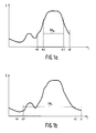
- the signal curve shown in FIG. 1a for example, as energy E or amplitude of the speech signal over time t has currently arrived and sampled up to time m1 and is in the form of digital samples.
- the continuously displayed signal curve is therefore present in the digital range as a sequence of discrete points, which, however, does not significantly influence the further explanation.
- the signal curve is now divided into three adjacent windows, of which the first window of the samples values range from m1 to m2 and is called the end window because it represents the temporary end of the speech signal in terms of time.
- the middle window ranges from the sample values m2 to the sample value m3.
- the actual word signal is accepted here, which has a higher energy value than the speech signal parts before and after it.
- the point m3 is gradually changed between a minimum distance and a maximum distance from the time m2 for the endpoint determination procedure to be described.
- the third window extends from the respective time m3 to time m4, the distance between which is again constant.
- each distance value can only belong to one of the windows, i.e. the middle window begins, when the first window reaches the sample value at the time m2, with the sample value immediately to the left, and the same applies to the third window.
- this fact is not further emphasized in the following explanation, but continues to assume a quasi-continuous signal curve.
- 1b assumes a later point in time at which the voice signal has already arrived by the point in time n1.
- a larger signal window is assumed, so that its start at time n3 is further away from time n2 than in FIG. 1a.
- the point in time n4 is the beginning of the initial window at an even earlier point in time.
- An essential criterion when determining the end points of the speech signal is the area of the speech signal within the signal window, reduced by a threshold value SW, which depends, among other things, on the area under the speech signal in the first and in the third window.
- SW which depends, among other things, on the area under the speech signal in the first and in the third window.
- the areas under the speech signal is represented by the sum of the digitized samples within the respective window.
- Fig. 1a the area in the start and end window is still relatively large, so that there is a higher threshold SW m . From the figure it can be seen immediately that the area reduced by the threshold value in the middle window becomes larger when the start and end windows are pulled further apart, ie when the subsequent arriving parts of the signal curve are waited for and the width of the signal window is chosen to be larger.
- the area of the speech signal that is briefly below the threshold value SW n within this signal window also makes a negative contribution, but is exceeded by the higher signal section to the left of it, so that extending the middle window extends beyond this area of the speech signal overall an increase in the total area in the signal window above the threshold value SW n results.
- the aforementioned start and end point will be determined with the method according to the flow chart in Figs. 2a and 2b.
- the symbol 10 means the start of the entire process, i.e. the beginning of the speech signal.
- various initial values are set, a number of samples corresponding to the length of the end window, the minimum signal window and the initial window are waited for before the method can start, and a special filter function is carried out. This consists in the fact that the smallest value is selected from each three consecutive samples and is fed to the method as a digital value. For example, every 10 ms a sample value is taken from the speech signal which represents the instantaneous value or the integrated value since the last sample value, and the sample values are digitized.
- a digital value is supplied to the method every 30 ms, so that 30 ms are available for carrying out the following method steps.
- the supplied digital values are saved because they will still be needed at later times, at least for a signal duration that corresponds to the sum of the predetermined maximum duration of the signal window and the two other windows.
- the energy EF k is determined in the initial window between the points m3 and m4 in FIG. 1a or n3 and n4 in FIG. 1b by summing up the signal values therein. In block 13, this value is divided by the length B F of the initial window and thus the average energy eF k is determined in this window.
- a comparison 14 checks whether this mean value eF k is smaller than a stored value eF sp , and if this is the case, this smaller value is stored in block 15, ie eF sp is replaced by the current value eF k .
- the energy ES k of the signal window with a minimum length is determined in block 16, i.e. the area under the speech signal curve between the points m2 and m3 in FIG the stored digital values are summed up in this area.
- a comparison 17 then checks whether this energy ES k is greater than a stored energy ES sp .
- the stored value is replaced by the new value in block 18, then or if the new value is not greater than the stored value, the mean energy ES k is determined in block 20 by the total energy ES k by the minimum width B s0 of the signal window is divided.
- the width B of this window and of the other windows is given by the number of digital values contained therein.
- a correction value thN is then determined in block 21 from the difference between the average energy eS k in the signal window and eF k in the initial window, which is divided by an assumed signal-to-noise ratio value SNR.
- the average energy in the end window is determined in block 22 in a manner corresponding to that in the initial window.
- Steps 12 to 22 run once for each newly arrived digital value, while connection point 23 now leads to a loop which is run through once for each permitted width of the signal window. These individual runs are indicated with index 1.
- This loop is indicated in FIG. 2 b, which begins with the connection point 23.
- this value 1 is set to the initial value zero.
- the average energy value eF1 of the initial window at the respective shift 1 is determined from the minimum width of the signal window in accordance with block 13, and in block 31 the value determined in this way is determined in relation to the average energy value of the final window determined in block 22 and to that correction value thN determined in block 21 is added in order to determine the threshold value thr.
- the energy ES 1 of the signal window is determined in the respective width by adding up the digital values in this window.
- the threshold value thr multiplied by the respective width B S1 of the signal window, is subtracted from this value.
- This effective energy EPS1 is regarded as the energy of the speech signal in the signal window, which protrudes beyond the interference signal, this interference signal can not be determined directly, but a probable value in the form of the threshold value is derived in the manner described above.
- the recognition process can begin each time the values are stored in block 35, so that when the steady state is finally recognized in block 38, the recognition process can already be well advanced that faster detection, possibly detection in real time, is possible in this way.
- a sound converter 40 picks up a speech signal and converts it into an electrical signal. This is fed to a unit 42 which takes samples from the continuous signal at regular time intervals and digitizes them. The unit 44 selects the smallest from three consecutive digitized samples and feeds the digital values thus determined to a memory 50. If the unit 42 takes a sample value from the speech signal every 10 ms, the memory 50 thus receives a new digital value every 30 ms. This is stored at an address which is supplied by a control unit 52 via the connection 53.
- control unit 52 also addresses the memory 50 for reading out the stored digital values, which are fed to a computing unit 54.
- these is also controlled by the control unit 52 via a connection 51 and carries out the computing steps which are indicated in the flowchart in FIGS. 2a and 2b with the blocks 12, 13, 16, 20 to 22 and 30 to 33.
- the computing unit 54 determines the energy in the initial window by summing up the corresponding digital values addressed by the control unit in the memory 50 and forms the average energy. This is fed via line 55 to a comparator 58 which receives the corresponding previously stored value at the other input from a second memory 56 via its data output line 57.
- the second memory 56 is also addressed by the control unit 52 via the line 59.
- comparator 58 If the newly determined value on line 55 is smaller than the stored value on line 57, comparator 58 generates a corresponding signal and feeds it to second memory 56, so that the new one is now at the addressed location the line 55 existing value is stored. This corresponds to blocks 14 and 17 in Fig. 2a.
- the other calculations and comparisons are also carried out in a corresponding manner, the computing unit 54 receiving the values required there, in particular in steps 21, 31 and 33, from the second memory 56 via the line 57.
- the control unit 52 supplies these values to the data input of the second memory 56 via the line 69.
- the counter 60 which counts the index 1.
- the counter 60 is set to the initial position by the control unit 52 via line 65 and supplied with counting clocks, as indicated in steps 29 and 36 in FIG. 2b.
- the comparison 38 is expediently carried out in the control unit 52.
- control unit 52 and the computing unit 54 are formed by a microprocessor. This can then also take over the function of the comparator 58 and the counter 60, so that overall a very simple structure results.
Landscapes
- Engineering & Computer Science (AREA)
- Computational Linguistics (AREA)
- Signal Processing (AREA)
- Health & Medical Sciences (AREA)
- Audiology, Speech & Language Pathology (AREA)
- Human Computer Interaction (AREA)
- Physics & Mathematics (AREA)
- Acoustics & Sound (AREA)
- Multimedia (AREA)
- Mobile Radio Communication Systems (AREA)
- Analogue/Digital Conversion (AREA)
- Traffic Control Systems (AREA)
Applications Claiming Priority (2)
| Application Number | Priority Date | Filing Date | Title |
|---|---|---|---|
| DE3739681 | 1987-11-24 | ||
| DE19873739681 DE3739681A1 (de) | 1987-11-24 | 1987-11-24 | Verfahren zum bestimmen von anfangs- und endpunkt isoliert gesprochener woerter in einem sprachsignal und anordnung zur durchfuehrung des verfahrens |
Publications (2)
| Publication Number | Publication Date |
|---|---|
| EP0319078A2 true EP0319078A2 (fr) | 1989-06-07 |
| EP0319078A3 EP0319078A3 (fr) | 1990-01-10 |
Family
ID=6341078
Family Applications (1)
| Application Number | Title | Priority Date | Filing Date |
|---|---|---|---|
| EP88202629A Withdrawn EP0319078A3 (fr) | 1987-11-24 | 1988-11-23 | Procédé et dispositif pour la détermination de début et de fin d'un mot isolé dans un signal de parole |
Country Status (4)
| Country | Link |
|---|---|
| US (1) | US4945566A (fr) |
| EP (1) | EP0319078A3 (fr) |
| JP (1) | JPH01167799A (fr) |
| DE (1) | DE3739681A1 (fr) |
Families Citing this family (25)
| Publication number | Priority date | Publication date | Assignee | Title |
|---|---|---|---|---|
| US5148429A (en) * | 1988-10-27 | 1992-09-15 | Kabushiki Kaisha Toshiba | Voice data transmission system and method |
| US5467288A (en) * | 1992-04-10 | 1995-11-14 | Avid Technology, Inc. | Digital audio workstations providing digital storage and display of video information |
| US5692104A (en) * | 1992-12-31 | 1997-11-25 | Apple Computer, Inc. | Method and apparatus for detecting end points of speech activity |
| US5634020A (en) * | 1992-12-31 | 1997-05-27 | Avid Technology, Inc. | Apparatus and method for displaying audio data as a discrete waveform |
| US5596680A (en) * | 1992-12-31 | 1997-01-21 | Apple Computer, Inc. | Method and apparatus for detecting speech activity using cepstrum vectors |
| US5675778A (en) * | 1993-10-04 | 1997-10-07 | Fostex Corporation Of America | Method and apparatus for audio editing incorporating visual comparison |
| DE4422545A1 (de) * | 1994-06-28 | 1996-01-04 | Sel Alcatel Ag | Start-/Endpunkt-Detektion zur Worterkennung |
| US5638486A (en) * | 1994-10-26 | 1997-06-10 | Motorola, Inc. | Method and system for continuous speech recognition using voting techniques |
| US5596679A (en) * | 1994-10-26 | 1997-01-21 | Motorola, Inc. | Method and system for identifying spoken sounds in continuous speech by comparing classifier outputs |
| US5638487A (en) * | 1994-12-30 | 1997-06-10 | Purespeech, Inc. | Automatic speech recognition |
| US5819217A (en) * | 1995-12-21 | 1998-10-06 | Nynex Science & Technology, Inc. | Method and system for differentiating between speech and noise |
| US6418431B1 (en) * | 1998-03-30 | 2002-07-09 | Microsoft Corporation | Information retrieval and speech recognition based on language models |
| US6321197B1 (en) * | 1999-01-22 | 2001-11-20 | Motorola, Inc. | Communication device and method for endpointing speech utterances |
| US6324509B1 (en) * | 1999-02-08 | 2001-11-27 | Qualcomm Incorporated | Method and apparatus for accurate endpointing of speech in the presence of noise |
| US7031908B1 (en) * | 2000-06-01 | 2006-04-18 | Microsoft Corporation | Creating a language model for a language processing system |
| US6865528B1 (en) * | 2000-06-01 | 2005-03-08 | Microsoft Corporation | Use of a unified language model |
| US8229753B2 (en) * | 2001-10-21 | 2012-07-24 | Microsoft Corporation | Web server controls for web enabled recognition and/or audible prompting |
| US7711570B2 (en) * | 2001-10-21 | 2010-05-04 | Microsoft Corporation | Application abstraction with dialog purpose |
| US8301436B2 (en) * | 2003-05-29 | 2012-10-30 | Microsoft Corporation | Semantic object synchronous understanding for highly interactive interface |
| US7200559B2 (en) * | 2003-05-29 | 2007-04-03 | Microsoft Corporation | Semantic object synchronous understanding implemented with speech application language tags |
| US8160883B2 (en) * | 2004-01-10 | 2012-04-17 | Microsoft Corporation | Focus tracking in dialogs |
| US8311819B2 (en) * | 2005-06-15 | 2012-11-13 | Qnx Software Systems Limited | System for detecting speech with background voice estimates and noise estimates |
| US8170875B2 (en) | 2005-06-15 | 2012-05-01 | Qnx Software Systems Limited | Speech end-pointer |
| US7568758B2 (en) * | 2007-01-03 | 2009-08-04 | Kolcraft Enterprises | High chairs and methods to use high chairs |
| US9099098B2 (en) * | 2012-01-20 | 2015-08-04 | Qualcomm Incorporated | Voice activity detection in presence of background noise |
Family Cites Families (3)
| Publication number | Priority date | Publication date | Assignee | Title |
|---|---|---|---|---|
| DE3243231A1 (de) * | 1982-11-23 | 1984-05-24 | Philips Kommunikations Industrie AG, 8500 Nürnberg | Verfahren zur erkennung von sprachpausen |
| JPS59115625A (ja) * | 1982-12-22 | 1984-07-04 | Nec Corp | 音声検出器 |
| US4821325A (en) * | 1984-11-08 | 1989-04-11 | American Telephone And Telegraph Company, At&T Bell Laboratories | Endpoint detector |
-
1987
- 1987-11-24 DE DE19873739681 patent/DE3739681A1/de not_active Withdrawn
-
1988
- 1988-11-18 US US07/274,093 patent/US4945566A/en not_active Expired - Fee Related
- 1988-11-22 JP JP63293724A patent/JPH01167799A/ja active Pending
- 1988-11-23 EP EP88202629A patent/EP0319078A3/fr not_active Withdrawn
Also Published As
| Publication number | Publication date |
|---|---|
| JPH01167799A (ja) | 1989-07-03 |
| EP0319078A3 (fr) | 1990-01-10 |
| US4945566A (en) | 1990-07-31 |
| DE3739681A1 (de) | 1989-06-08 |
Similar Documents
| Publication | Publication Date | Title |
|---|---|---|
| EP0319078A2 (fr) | Procédé et dispositif pour la détermination de début et de fin d'un mot isolé dans un signal de parole | |
| DE3233637C2 (de) | Vorrichtung zur Bestimmung der Dauer von Sprachsignalen | |
| DE69917361T2 (de) | Vorrichtung zur Sprachdetektion bei Umgebungsgeräuschen | |
| DE3101851C2 (de) | Vorrichtung zum Erkennen von Sprache | |
| DE3645118C2 (fr) | ||
| DE69121312T2 (de) | Geräuschsignalvorhersagevorrichtung | |
| DE2536585C3 (de) | Anordnung zur statistischen Signalanalyse | |
| DE2034623C2 (de) | Verfahren für das Erkennen von Sprachsignalen in Rauschen | |
| DE3723078A1 (de) | Verfahren zur erkennung von zusammenhaengend gesprochenen woertern | |
| DE2326517A1 (de) | Verfahren und schaltungsanordnung zum erkennen von gesprochenen woertern | |
| DE3422877C2 (fr) | ||
| EP0533261A2 (fr) | Procédé et dispositif pour la reconnaissance de mots prononcés dans un signal de parole | |
| WO2001001389A2 (fr) | Procede et dispositif de reconnaissance vocale | |
| EP0285221A2 (fr) | Procédé pour la reconnaissance de la parole continue | |
| DE3149134C2 (de) | Verfahren und Vorrichtung zur Bstimmung von Endpunkten eines Sprachausdrucks | |
| EP0533259B1 (fr) | Procédé et dispositif pour reconnaitre une suite de mots | |
| DE19639844A1 (de) | Verfahren zum Ableiten wenigstens einer Folge von Wörtern aus einem Sprachsignal | |
| EP0285222B1 (fr) | Procédé pour la reconnaissance de la parole continue | |
| EP0076233A1 (fr) | Procédé et dispositif pour traitement digital de la parole réduisant la redondance | |
| DE4031421C2 (de) | Musteranpassungssystem für eine Spracherkennungseinrichtung | |
| EP0677836A1 (fr) | Procédé pour rechercher une suite de mots et arrangement pour la réalisation du procédé | |
| DE3710507A1 (de) | Verfahren zum erkennen kontinuierlich gesprochener woerter | |
| DE2719175A1 (de) | Schallanalysiereinrichtung | |
| EP0703569A1 (fr) | Dispositif de détection de mots à partir d'un signal vocal | |
| DE2920041C2 (de) | Verfahren zum Verifizieren von Signalen, und Anordnung zum Durchführen des Verfahrens |
Legal Events
| Date | Code | Title | Description |
|---|---|---|---|
| PUAI | Public reference made under article 153(3) epc to a published international application that has entered the european phase |
Free format text: ORIGINAL CODE: 0009012 |
|
| AK | Designated contracting states |
Kind code of ref document: A2 Designated state(s): DE FR GB |
|
| PUAL | Search report despatched |
Free format text: ORIGINAL CODE: 0009013 |
|
| AK | Designated contracting states |
Kind code of ref document: A3 Designated state(s): DE FR GB |
|
| 17P | Request for examination filed |
Effective date: 19900626 |
|
| STAA | Information on the status of an ep patent application or granted ep patent |
Free format text: STATUS: THE APPLICATION IS DEEMED TO BE WITHDRAWN |
|
| 18D | Application deemed to be withdrawn |
Effective date: 19920603 |