EP0319204A1 - Méthode et dispositif pour enlever de vieux pieux - Google Patents
Méthode et dispositif pour enlever de vieux pieux Download PDFInfo
- Publication number
- EP0319204A1 EP0319204A1 EP19880311172 EP88311172A EP0319204A1 EP 0319204 A1 EP0319204 A1 EP 0319204A1 EP 19880311172 EP19880311172 EP 19880311172 EP 88311172 A EP88311172 A EP 88311172A EP 0319204 A1 EP0319204 A1 EP 0319204A1
- Authority
- EP
- European Patent Office
- Prior art keywords
- pile
- bucket
- high pressure
- pressure water
- old
- Prior art date
- Legal status (The legal status is an assumption and is not a legal conclusion. Google has not performed a legal analysis and makes no representation as to the accuracy of the status listed.)
- Granted
Links
- 238000000034 method Methods 0.000 title claims description 13
- XLYOFNOQVPJJNP-UHFFFAOYSA-N water Substances O XLYOFNOQVPJJNP-UHFFFAOYSA-N 0.000 claims abstract description 152
- 230000007246 mechanism Effects 0.000 claims abstract description 90
- 230000002093 peripheral effect Effects 0.000 description 14
- 239000002245 particle Substances 0.000 description 6
- 238000010276 construction Methods 0.000 description 5
- 230000008602 contraction Effects 0.000 description 4
- 230000003014 reinforcing effect Effects 0.000 description 3
- 238000009434 installation Methods 0.000 description 2
- 230000004075 alteration Effects 0.000 description 1
- 230000015572 biosynthetic process Effects 0.000 description 1
- 238000007599 discharging Methods 0.000 description 1
- 239000002184 metal Substances 0.000 description 1
- 230000000149 penetrating effect Effects 0.000 description 1
- 239000004576 sand Substances 0.000 description 1
- 238000007789 sealing Methods 0.000 description 1
Images











Classifications
-
- E—FIXED CONSTRUCTIONS
- E21—EARTH OR ROCK DRILLING; MINING
- E21D—SHAFTS; TUNNELS; GALLERIES; LARGE UNDERGROUND CHAMBERS
- E21D23/00—Mine roof supports for step- by- step movement, e.g. in combination with provisions for shifting of conveyors, mining machines, or guides therefor
- E21D23/16—Hydraulic or pneumatic features, e.g. circuits, arrangement or adaptation of valves, setting or retracting devices
-
- E—FIXED CONSTRUCTIONS
- E02—HYDRAULIC ENGINEERING; FOUNDATIONS; SOIL SHIFTING
- E02D—FOUNDATIONS; EXCAVATIONS; EMBANKMENTS; UNDERGROUND OR UNDERWATER STRUCTURES
- E02D9/00—Removing sheet piles bulkheads, piles, mould-pipes or other moulds or parts thereof
- E02D9/005—Removing sheet piles bulkheads, piles, mould-pipes or other moulds or parts thereof removing the top of placed piles of sheet piles
-
- Y—GENERAL TAGGING OF NEW TECHNOLOGICAL DEVELOPMENTS; GENERAL TAGGING OF CROSS-SECTIONAL TECHNOLOGIES SPANNING OVER SEVERAL SECTIONS OF THE IPC; TECHNICAL SUBJECTS COVERED BY FORMER USPC CROSS-REFERENCE ART COLLECTIONS [XRACs] AND DIGESTS
- Y10—TECHNICAL SUBJECTS COVERED BY FORMER USPC
- Y10T—TECHNICAL SUBJECTS COVERED BY FORMER US CLASSIFICATION
- Y10T83/00—Cutting
- Y10T83/364—By fluid blast and/or suction
Definitions
- This invention relates to a method and apparatus for removing old and unneeded piles embedded in the ground.
- old piles cannot sufficiently support the new building. If old piles were to be utilized as support piles for a new building, they would be of little value and would rather be dangerous because their strength has generally deteriorated due to long use of the concrete and reinforcing bars constituting them.
- An object of the invention is to provide a method and apparatus for readily removing large old piles embedded in the ground.
- Another object of the invention is to provide a method and apparatus for removing an old pile while simultaneously digging a pile bore for a new pile.
- a bucket is set to surround an upper end portion of an old pile, an intermediate portion of the old pile is radially cut by jetting high pressure water from the bucket from the center and opposite sides of the outer periphery of the old pile. Then, the pile portion above the cut portion is chucked with a chuck mechanism, and in this state the chuck mechanism is turned to twistingly sever the pile portion above the cut portion with the resultant stress. The above sequence of operations is repeated to thereby remove the entire old pile.
- an old pile embedded in the ground can be removed readily, efficiently and progressively from an upper portion by radially cutting an intermediate portion of the old pile with high pressure water and twistingly severing the pile portion above the cut portion with a chuck mechanism.
- the old pile is cut with high pressure water, there are no noise or vibration problems, and the pile removal operation can be performed even in residential or urban areas.
- the removal of the old pile and expansion of the pile bore can be effected simultaneously.
- the pile bore of the old pile can be used as the pile bore of the new pile.
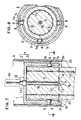
- FIGS 1 to 12 show a first embodiment of the apparatus for removing an old pile according to the invention.
- the apparatus, generally designated at 1, for removing an old pile substantially comprises a bucket 4 having a disk-like top 2 and a cylindrical peripheral wall 3 depending from the edge of the top 2 and open at the bottom.
- the bucket 4 is provided with a chuck mechanism 5, and a casing 6 is fitted on the bucket 4.
- the chuck mechanism 5 includes first chucks 5a provided on the inner periphery of the peripheral wall 3 of the bucket 4 for chucking an old pile P and second chucks 5b provided on the inner periphery of the casing 6 for chucking the bucket 4.
- the first chucks 5a are provided on the bucket inner periphery at an interval of 90 degrees.
- Each first chuck includes a first urging member 7a.
- the individual urging members 7a are urged against the pile outer periphery by a hydraulic or like piston-cylinder mechanism (not shown).
- the first urging members 7a may be accommodated in the peripheral wall 3.
- the second chucks 5b are provided on the inner periphery of the casing 6 and include respective second urging members 7b which are circumferentially spaced apart to have the same phases as the first chucks.
- the second urging members 7b are normally accommodated in the casing 6. They can be driven by a piston-cylinder mechanism (not shown) to project inwardly in four different directions so that their inner surfaces are urged against the outer periphery of the bucket 4, thus securing the bucket 4 and casing 6 to each other.
- Figures 5 and 6 show a different example of the chuck mechanism 5.
- the urging members 7 are each provided on the casing 6 via a piston-cylinder mechanism 8.
- the piston-cylinder mechanisms 8 are driven hydraulically to be elongated and contracted.
- the urging members 7 are accommodated in the casing 6 to be flush with the casing inner periphery.
- the urging members 7 are urged against the outer periphery of an old pile P in four directions through through holes 9 formed in the peripheral wall 3 of the bucket 4, thus securing the casing 6 and pile P to each other.
- the alignment of the urging members 7 and through holes 9 is necessary.
- the chuck mechanism 5 is simplified in structure, so that it can be manufactured inexpensively.
- Figures 7 and 8 show a further example of the chuck mechanism 5.
- the chuck mechanism 5 is provided in the bucket 4.
- the piston-cylinder mechanisms 8 are each capable of elongation and contraction in both the inner and outer directions.
- Each piston-cylinder mechanism 8 has urging members 7c and 7d projecting from the opposite ends.
- the inner surface of the inwardly projecting urging member 7c is urged against the outer periphery of an old pile P, while the outwardly projecting urging member 7d is urged against the inner surface of the casing 6, thus securing the pile P and casing 6 to each other.
- FIGS 9 and 10 show a still further example of the chuck mechanism 5.
- This chuck mechanism 5 includes a support shaft 10 downwardly extending from the lower end of the bucket 4, a pair of arcuate operating rods 11 having urging members 7a and 7b and each having one end rotatably mounted on the support shaft 10, and a piston-cylinder mechanism 8 provided on the free end of one of the operating rods 11.
- two pairs of operating rods 11 and associated piston-cylinder mechanisms 8 are provided side by side in the vertical direction.
- the piston-cylinder mechanism 8a is constructed so as to cause contraction of the upper pair of operating rods 11a
- the other piston-cylinder mechanism 8b is constructed so as to cause expansion of the lower pair of operating rods 11b.
- the contact surfaces of the urging members 7 may be formed with fine antiskid irregularities.
- a swivel joint 12 is provided on the center of the top 2 of the bucket 4.
- the swivel joint 12 has a downwardly depending first high pressure water jet unit 13.
- the unit 13 includes a high pressure water pipe 15 depending from the swivel joint 12 via a packer 14 and a downwardly directed high pressure water jet nozzle 16 and horizontally directed high pressure water jet nozzles 17, the nozzles 16 and 17 being provided on the lower end of the pipe 15.
- the peripheral wall 3 of the bucket 4 is provided with diametrically opposed second high pressure water jet units 21.
- Each second high pressure water jet unit 21 includes a vertical high pressure water passage 18 extending through the wall 3, a downwardly directed high pressure water jet nozzle 19 and a horizontally inwardly directed high pressure water jet nozzle 20, the nozzles 19 and 20 being provided at the lower end of the high pressure water passage 18.
- the horizontally directed high pressure water jet nozzles 17 of the first high pressure water jet unit 13 is located at the center of the open bottom of the bucket 4 and at the same level as the high pressure water jet nozzles 20 of the second high pressure water jet units 21.
- the casing 6 is also provided with diametrically opposed third high pressure water jet units 24.
- Each third high pressure water jet unit 24 includes a vertical high pressure water passage 22 extending through the casing 6 and open at the lower end thereof and a high pressure water jet nozzle 23 provided at the lower end of the passage 22 for downwardly jetting high pressure water.
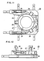
- the casing 6 is set by operating a setting unit 25 such that it surrounds an upper end portion of the pile P.
- the setting unit 25 is shown in Figures 11 and 12.
- the setting unit 25 includes a base 26, in which are provided a contractible chuck 27, jacks 28 supporting and capable of vertically displacing the chuck 27 and swinging mechanisms 29 for swinging the jacks 28.
- the casing 6 is chucked in the chuck 27 of the setting unit 25 and is set in an operating position by operating the jacks 28 and swinging mechanisms 29 to surround an upper end portion of a sufficient length or vertical dimension.
- the casing 6 is provided with the third high pressure water jet units 24, it is advanced into the ground by digging out the earth under its lower end by downwardly jetting high pressure water from the high pressure water jet nozzles 23.
- a post 30 of a machine such as the kelley-bar of an earth drill, is connected to the center of the upper surface of the top 2 of the bucket 4, and the bucket 4 is then suspended from a crane (not shown) via a wire or wires.
- high pressure water hoses 67 are connected respectively to the high pressure water pipe 15 and high pressure water passages 18 and 22 of the respective high pressure water jet units 13, 21 and 24 at the swivel joint 12.
- the high pressure water hoses have their other ends coupled to an ultra-high pressure water jet unit (not shown) which can control supply of jet water to each of the high pressure water jet nozzles 16, 17, 19, 20 and 23 of the high pressure water jet units 13, 21 and 24.
- an oil pressure hose extending from an oil pressure mechanism (not shown) is connected to each of the piston-cylinder mechanisms 8 of the chuck mechanism 5.
- the ultra-high pressure water jet unit noted above preferably is able to discharge water under a maximum pressure of 3,800 kg/cm at a maximum rate of 86 litres/min.
- water under an extremely high pressure is jetted from the high pressure water jet nozzles 16, 17, 19, 20 and 23 of the high pressure water jet units 13, 21 and 24, so that it is possible to sever concrete and reinforcing bars c.
- the bucket 4 suspended in the air is lowered slowly into the casing 6 while turning it in alternate, i.e., normal and reverse, directions every 180 degrees, for instance, and at the same time high pressure water containing fine abrasive particles is jetted downwardly from the high pressure water jet nozzles 16 and 19 of the first and second high pressure water jet units 13 and 21.
- a vertical bore h is gradually formed from the center of the top of the pile P by the pressure of the high pressure water from the nozzle 16, so that the first high pressure water jet unit 13 is gradually inserted into the vertical bore h, and also an annular groove is formed under the bucket 4 by the pressure of the high pressure water from the nozzle 19, so that the bucket 4 is gradually lowered into the ground.
- the bucket 4 progressively surrounds the upper end portion of the pile P until the packer 14 rests on the top of the pile P.
- the jetting of high pressure water from the high pressure water jet nozzles 16 and 19 is stopped, and high pressure water including fine abrasive particles is jetted from the horizontally directed high pressure water jet nozzles 17 and 20 of the first and second high pressure water jet units 13 and 21 ( Figure 2).
- the high pressure water jetted from the high pressure water jet nozzles 17 horizontally cuts the pile P from the center thereof toward the outer periphery, while high pressure water jetted from the high pressure water jet nozzles 20 horizontally cut the pile P together with reinforcing bars c from the outer periphery toward the center of the pile.
- the upper open end of the vertical bore h formed centrally of the pile by the first high pressure water jet unit 13 is sealed with the packer 14, and high pressure water is jetted from the high pressure water jet nozzles 16 and 17 to increase the pressure in the cut space of the pile P with water. In this way, the concrete portion that has not been cut is cut.
- the casing 6 is swung by operating the setting unit 25 to cause swinging of the first and second chucks 5a and 5b together with the casing 6.
- the pile P is not swung. Therefore, a stress produced by the swinging of the casing 6 acts on the upper end portion P′ of the pile P to twist the pile portion left uncut by the high pressure water, thus severing the portion P′ of the pile above the cut section d.
- the casing 6 is lowered by the setting unit 25 to surround a new upper end portion of the remaining pile P, the bucket 4 is also lowered to surround the new pile upper end portion, and the new pile upper end portion which has a length substantially corresponding to the height of the bucket 4 is severed and removed by the same sequence of operations as described above. By repeating the above sequence of operations, the entire length of the pile can be removed from the ground.
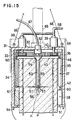
- FIGS. 13 to 23 show a second embodiment of the apparatus for removing a pile with self-turning means for causing the bucket to rotate itself.
- the apparatus generally designated at 31 comprises a bucket 34 open at the lower end and having a disk-like top 32 and a cylindrical wall 33 depending from the edge of the top 32.
- a cylindrical rotary frame 35 is provided on an upper portion of the inner wall surface of the bucket 34.
- An internal swinging gear 36 is secured to the upper end of the inner wall surface of the rotary frame 35.
- a first chuck mechanism 37 is provided on the inner wall surface of the rotary frame 35 below the swinging gear 36 such that it is rotatable in unison with the rotary frame 35.
- a second chuck mechanism 38 is provided integrally with the inner wall surface of the bucket 34 below the rotary frame 35.
- Each oil pressure motor 39 has a downwardly extending shaft 40 penetrating the top 32 of the bucket 34 into the bucket 34.
- a drive gear 41 in mesh with the swinging gear 36.
- the rotary frame 35 and first chuck mechanism 37 are rotatably supported by a shelf member 42 provided on a vertically intermediate portion of the inner wall surface of the cylindrical wall 33 such that the rotary member 35 and first chuck mechanism 37 are rotatable with respect to the cylindrical wall 33.
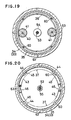
- the first chuck mechanism 37 includes a pair of semicircular chuck frames 43 obtained by axially bisecting a cylindrical member.
- the chuck frames 43 each has its inner surface formed with fine antiskid irregularities.
- the rotary frame 35 has its inner surface provided with a plurality of axial ridges 44, and the chuck frames 43 have their outer surfaces formed with axial grooves 45 corresponding in position to and receiving the axial ridges 44.
- the first chuck mechanism 37 thus can be rotated together with the rotary frame 35 by the engagement between the axial ridges 44 and the axial grooves 45 irrespective of whether it is in a contracted or expanded state.
- the upper edge of the first chuck mechanism 37 is provided with piston-cylinder mechanisms 46 between the two chuck frames 43 to cause expansion and contraction of the inner space of the first chuck mechanism.
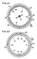
- the second chuck mechanism 38 has substantially the same construction as the first chuck mechanism 37. As shown in Figures 22 and 23, it includes a pair of semicircular chuck frames 47 obtained by axially bisecting the cylindrical member.
- the chuck frames 47 each has its inner surface formed with fine antiskid irregularities.
- the cylindrical wall 33 has its inner surface formed with a plurality of axial ridges 48, and the chuck frames 47 have their outer surface formed with vertical grooves 49 corresponding to and receiving the axial ridges 48.
- the second chuck mechanism 38 thus can be rotated together with the peripheral wall 33 with the engagement between the axial ridges 48 and the vertical grooves 49 irrespective of whether it is in an expanded or contracted state.
- the second chuck mechanism 38 has its upper edge provided with piston-cylinder mechanisms 50 between the chuck frames 47 to cause expansion and contraction of the inner space of the second chuck mechanism and also has its lower edge received on an annular support 51 formed on the lower edge of the cylindrical wall 33.
- a swivel joint 52 is provided on the center of the top 32 of the bucket 34, and a first high pressure water jet unit 53 is provided such that it extends downwardly from the swivel joint 52.
- the first high pressure water jet unit 53 includes a high pressure water pipe 55 depending downwardly from the swivel joint 52 via a packer 54, a downwardly directed high pressure water jet nozzle 56 and horizontally directed high pressure water jet nozzles 57 provided at the lower open end of the pipe 55.
- the bucket 34 is provided with a second high pressure water jet mechanism 58 extending from the swivel joint 52 and capable of jetting water under the same high pressure as the first high pressure water jet mechanism 53.
- the second high pressure water jet mechanism 58 includes a plurality of high pressure water pipes 59 extending from the swivel joint 52 in the radial directions of the top 32, high pressure water passages 60 each extending longitudinally from the end of each high pressure water pipe 59 past the swinging gear 36 and chuck frames 43 of the first chuck mechanism 37, and horizontally directed high pressure water jet nozzles 61 each provided on the lower open end of each high pressure water passage 60.
- the high pressure water from the nozzles 57 is jetted from the center of the bucket 34 toward the outer periphery thereof, and high pressure water from the nozzles 61 is jetted from the outer periphery of the bucket toward the center thereof at the same level as that of the water jetted from the nozzles 57.
- the bucket 34 is further provided with a third high pressure water jet unit 62 in addition to the first and second high pressure water jet units 53 and 58.
- the third high pressure water jet unit 62 includes a plurality of high pressure water passages 63 extending from the swivel joint 52 through and radially of the top 32 and vertically extending through the cylindrical wall 33 and a plurality of high pressure water jet nozzles 64 each provided at the opening of each high pressure water passage 63 at the lower end of the cylindrical wall 33. High pressure water is jetted downwardly from each high pressure water jet nozzle 64.
- a post 65 of a machine such as the kelley-bar of an earth drill, is connected to the center of the upper surface of the top 32 of the bucket 34, and the bucket 34 is suspended from a crane (not shown) via wires 66, as shown in Figure 13.
- Pressure water hoses 67 are connected at their respective one ends to the high pressure water pipe 55, high pressure water pipes 59 and high pressure water passages 63 of the first, second and third high pressure water jet units 53, 58 and 62 at the swivel joint 52.
- the other ends of the high pressure water hoses 67 are coupled to an ultra-high pressure water jet unit (not shown) for controlling jet water for each high pressure water jet nozzle of each high pressure water jet unit.
- An oil pressure hose 68 extending from an oil pressure mechanism (not shown) is connected to the two oil pressure motors 39 and piston-cylinder mechanisms 46 and 50 of the first and second chuck mechanisms 37 and 38.
- a casing 69 consisting of a metal cylinder is driven into the ground to surround the pile P to remove the earth surrounding the pile.
- the bucket 34 suspended in air is lowered slowly while turning it in alternately opposite directions at an interval of 180°, for instance, by the post 65.
- high pressure water containing fine abrasive particles is jetted from the high pressure water jet nozzle 56 of the first high pressure water jet unit 53 toward the center of the pile, while downwardly jetting high pressure water from the high pressure water jet nozzles 64 of the third high pressure water jet unit 62.
- an axial bore h is gradually formed in the center of the pile P by the pressure of the high pressure water from the nozzle 56, and the first high pressure water jet unit 53 is gradually inserted into the pile P.
- the earth surrounding the pile P is dug by high pressure water jetted from the high pressure water jet nozzles 64, and the bucket 34 is gradually lowered into the ground.
- the bucket 34 is gradually fitted on an upper end portion of the pile P, and the packer 54 is eventually set on the top of the pile P.
- the jetting of high pressure water from the high pressure water jet nozzles 56 and 64 is stopped, and high pressure water containing fine abrasive particles is jetted horizontally from the high pressure water jet nozzles 57 and 61 of the first and second high pressure water jet nozzles 53 and 58 while turning the bucket 34 in alternately opposite directions at an interval with every rotation by 90° or 180° (Figure 15).
- the pile is thus cut from its radial center and opposite sides of the outer periphery at the same level.
- the pressure in the cut space of the pile P is increased with water as in the previous embodiment, i.e., by sealing the upper end opening of the vertical bore h formed in the center of the pile P with the packer 54 and jetting high pressure water from the high pressure water jet nozzles 56 and 57. In this way, the pile P can be sufficiently cut radially.
- the jetting of high pressure water from the nozzles is stopped, and the first and second chuck mechanisms 37 and 38 are contracted by forcing operating oil to the piston-cylinder mechanisms 46 and 50 of the first and second chuck mechanisms 37 and 38 to strongly chuck the portion P′ of the pile P above the cutting section d of with the first chuck 37 and strongly chuck a portion of the pile P below the cutting section d with the second chuck mechanism 38.
- the first chuck mechanism 37 is rotated by the swinging gear 36 via the rotary frame 35. Since the second chuck mechanism 38 is not rotated at this time, a stress produced with the rotation of the first chuck mechanism 37 acts on the upper end portion P′ of the pile to be received by the second chuck mechanism 38. Thus, the pile portion P′ above the cutting section d which still remains integral with the rest of the pile P is severed by twisting.
- the bucket 34 is lowered again to surround a new upper end portion of the pile P, which is then severed and removed in the manner as described above.
- the above sequence of operations is performed repeatedly to remove the entire length of the pile P from the ground.
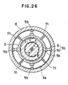
- Figures 24 to 28 illustrate a third embodiment of the invention applied to a pile removal apparatus, which includes pile hole digging means provided in the pile removal apparatus which is substantially the same as the first embodiment.
- a first high pressure water jet unit 13 for jetting high pressure water in the downward direction and horizontal directions is provided such that it depends from the inside of a bucket 4 which is open at the bottom and fitted on the top of the pile P.
- Second high pressure water jet units 21 for jetting high pressure water in the horizontal directions and downward direction are provided at the lower end of the peripheral wall 3 of the bucket 4.
- the peripheral wall 3 of the bucket 4 is provided with first chucks 5a for chucking the pile P and second chucks 5b for urging the inner wall surface of the casing 6. These chucks are accommodated in the peripheral wall 3.
- the top 2 of the bucket 4 has an outer flange 2a, and the lower end of the peripheral wall 3 of the bucket 4 has an outer flange 3a.
- the inner diameter of the peripheral wall 3 is set to be substantially equal to the outer diameter D1 of the old pile P, and the casing 6 has an outer diameter substantially equal to the diameter D2 of a bore for a pile which is to be newly driven.
- the diameter of the upper and lower flanges 2a and 3a is set to a value corresponding the diameter D2 of the new pile bore plus the thickness of the casing 6.
- the lower flange 3a extending from the lower end of the peripheral wall 3 of the bucket 4 is provided with pile bore digging means 71.
- the lower flange 3a has a plurality of through holes 72 formed at a suitable angular interval (in this embodiment four through holes being formed at an interval of 90°).
- Support shafts 73 are provided such that they radially traverse the respective through holes 72.
- a digging member 74 is rotatably supported on each support shaft 73.
- the digging member 74 has two wings 74a and 74b made integral into an L-shaped form and each having a digging edge 75.
- the wings 74a and 74b have a length greater than the distance between an edge 72′ of the through hole 72 and the support shaft 73, so that the digging member 74 can engage with the lower surface of the lower flange 3a adjacent to the through hole 72.
- three narrow digging members 74 are provided side by side and in a spaced-apart relation to one another in each through hole 72.
- the casing 6 is chucked with the chuck 27 of the setting unit 25 shown in Figures 11 and 12 and is brought to surround an upper end portion of the old pile P while being swing by operating the jacks 28 and swinging mechanisms 29. If the casing 6 has the third high pressure water jet unit, high pressure water is jetted downwardly.
- the digging means 71 is provided on the lower flange 3a of the bucket 4, by turning the bucket 4 the digging means 71 digs the ground surrounding the old pile P to increase the diameter of the pile bore.
- the wing 74a front with respect to the rotating direction of the bucket 4 is urged by the earth and rotated rearwardly, and the upper surface of the wing 74b rear with respect to the rotating direction of the bucket 4 is upwardly brought into engagement with the edge 72′ of the through hole 72.
- the digging member 74 can no longer be rotated, the digging edge 75 of the wing 74a wedges into the ground.
- the earth With the wedging of the digging member 74 into the ground, the earth is dug up along the upper surface of the wing 74a, thus discharging the earth onto the upper surface of the bucket 4 through the front half of the through hole 72. Since at this time the rear half of the through hole 72 is closed by the rear wing 74b, the dug earth cannot be returned to the pile bore.
- the digging edge 75 of the wing 74b digs the ground, while the wing 74a closes the rear half of the through hole 72 to prevent the fall of the earth through the through hole.
- the bucket eventually surrounds an upper end portion of the pile P, the packer 14 is set on top of the pile P, and the earth is collected on top of the lower flange 3a.
- the earth that has been collected on the lower flange 3a is brought upwardly through the space between the casing 6 and the outer periphery of the peripheral wall 3 of the bucket to be fed through a discharge opening 2b formed in the upper flange 2a onto the top 2 of the bucket 4.
- the downward jetting of high pressure water from the first and second high pressure water jet units 13 and 21 is stopped, and high pressure water containing abrasive particles is jetted from the horizontal jet nozzles 17 and 20 while turning the bucket in alternately opposite directions.
- the old pile P is cut horizontally from its center and opposite sides of its outer periphery.
- the jetting of high pressure water from the nozzles 17 and 20 is stopped, and the outer periphery of a portion P′ of the old pile P above the cutting section d is strongly chucked with the first chucks 5a while securing the bucket 4 to the casing 6 with the second chucks 5b by operating the piston-cylinder mechanisms 8.
- the casing 6 is swung with the setting unit 25 to sever the old pile P at the cutting section d by twisting.
- the bucket 4 is then raised together with the separated upper end portion P′ of the pile, and the earth collected on the upper surface of the bucket 4 is discharged onto the ground surface.
- the old pile is removed progressively from upper portions, and concurrently an increased diameter pile bore for a pile to be newly driven is formed.
- Figures 29 to 30 show a fourth embodiment of the invention.
- This embodiment has digging means provided in a pile removal apparatus having substantially the same structure as the second embodiment without use of any setting unit.
- the lower end of the peripheral wall 33 of the bucket 34 has an outer flange 33a, and the diameter of the flange 33a is set to be substantially the same as the diameter D2 of a new pile.
- the flange 33a is provided with a plurality of pile bore digging means 71 disposed at predetermined intervals.
- Each digging means 71 as shown in Figures 27 and 28, includes a digging member 74 rotatably supported on a support shaft 73 radially traversing each through hole 72.
- the self-turning means, chuck mechanisms and high pressure water jet units provided on the bucket 34 have the some construction as in the second embodiment, and are thus designated by like reference numerals with omission of duplicated description.
- the bucket 4 is suspended from a crane (not shown) via wires 66 and lowered to surround the pile P while turning it in alternately opposite directions with the post 65 and downwardly jetting high pressure water.
- a vertical bore h is formed in the center of the pile, and the earth surrounding the old pile P is dug by high pressure water and digging means to increase the pile bore diameter.
- the bucket 34 is brought into the ground to surround an upper end portion of the old pile P.
- the pile P is radially cut by horizontally jetting high pressure water from the center and opposite sides of the outer periphery of the pile. Thereafter, the outer periphery of the pile portion P′ above the cutting section d is strongly chucked with the first chuck mechanism 37, and a pile portion below the cutting section d is chucked with the second chuck mechanism 38. Then, the first chuck mechanism 37 is turned with the self-turning means to sever the pile P at the cutting section d. Subsequently, the bucket 4 is raised to remove the separated upper end portion P′ of the pile together with the earth on the flange 33a and on the top 32 of the bucket 34.
- sequence of operations as described above is repeatedly performed, thus removing the entire length of the old pile and forming an increased diameter pile bore for the installation of a new pile in the same place.
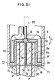
- Figure 31 shows a further embodiment of the invention.
- the earth produced as the ground is dug by digging means 71 provided on the bucket 4 is not collected on the top 2 of the bucket 4, but it is immediately discharged on the ground by a sand pump or an air lifter (not shown).
- the top 2 has the same diameter as the outer periphery 3, and a mud-lifting pipe 76 extends above the flange 3a.
- earth is not collected on the bucket 4, so that it is possible to perform quick operation and reduce the time consumption. Further, the structure of the bucket 4 can be simplified.
- a rotatable bucket is set to surround an upper end portion of an old pile burried in the ground, the ground surrounding the pile is dug to increase the pile bore diameter if necessary, and an upper end portion of the pile is radially severed by jetting high pressure water and also twisting it.
- an old pile can be removed readily, efficiently and progressively from upper portions by operations conducted on the ground.
- the pile bore diameter can be simultaneously increased.
- the construction work can be simplified, and the time consumption for the work can be reduced.
Landscapes
- Engineering & Computer Science (AREA)
- Mining & Mineral Resources (AREA)
- Life Sciences & Earth Sciences (AREA)
- General Life Sciences & Earth Sciences (AREA)
- General Engineering & Computer Science (AREA)
- Civil Engineering (AREA)
- Paleontology (AREA)
- Structural Engineering (AREA)
- Geochemistry & Mineralogy (AREA)
- Geology (AREA)
- Placing Or Removing Of Piles Or Sheet Piles, Or Accessories Thereof (AREA)
- Excavating Of Shafts Or Tunnels (AREA)
- Earth Drilling (AREA)
Applications Claiming Priority (6)
| Application Number | Priority Date | Filing Date | Title |
|---|---|---|---|
| JP30146387A JPH0643698B2 (ja) | 1987-12-01 | 1987-12-01 | 既設杭の除去方法及び装置 |
| JP301463/87 | 1987-12-01 | ||
| JP30081/88 | 1988-02-13 | ||
| JP30080/88 | 1988-02-13 | ||
| JP3008088A JPH0676689B2 (ja) | 1988-02-13 | 1988-02-13 | 既設杭の除去方法及びその装置 |
| JP3008188A JPH0676690B2 (ja) | 1988-02-13 | 1988-02-13 | 既設杭を除去すると共に新設杭用の杭孔を掘削する杭孔掘削法及びその装置 |
Publications (2)
| Publication Number | Publication Date |
|---|---|
| EP0319204A1 true EP0319204A1 (fr) | 1989-06-07 |
| EP0319204B1 EP0319204B1 (fr) | 1992-09-16 |
Family
ID=27286829
Family Applications (1)
| Application Number | Title | Priority Date | Filing Date |
|---|---|---|---|
| EP19880311172 Expired - Lifetime EP0319204B1 (fr) | 1987-12-01 | 1988-11-25 | Méthode et dispositif pour enlever de vieux pieux |
Country Status (6)
| Country | Link |
|---|---|
| US (1) | US4900198A (fr) |
| EP (1) | EP0319204B1 (fr) |
| KR (1) | KR970007387B1 (fr) |
| AU (1) | AU608919B2 (fr) |
| CA (1) | CA1298274C (fr) |
| DE (1) | DE3874695T2 (fr) |
Cited By (4)
| Publication number | Priority date | Publication date | Assignee | Title |
|---|---|---|---|---|
| WO2001051716A1 (fr) * | 2000-01-13 | 2001-07-19 | Dae Yang Geotechnic Pte. Ltd. | Appareil a arracher les pieux |
| WO2017007946A1 (fr) | 2015-07-07 | 2017-01-12 | Mimouni Nabil | Système d'extraction de pieux |
| CN111236231A (zh) * | 2020-01-17 | 2020-06-05 | 徐胜祥 | 一种便于下放的后置式砼桩头断裂方法 |
| EP4311883A1 (fr) * | 2022-07-28 | 2024-01-31 | DISA International Holding B.V. | Procédé et outil pour retirer un coulis d'une extrémité supérieure d'un ancrage de coulis sous l'eau |
Families Citing this family (21)
| Publication number | Priority date | Publication date | Assignee | Title |
|---|---|---|---|---|
| US5238069A (en) * | 1991-09-19 | 1993-08-24 | Superior Offshore Services, Inc. | System for preventing cutting gas explosion during subterranean pipe cutting operations |
| WO1998007955A2 (fr) * | 1996-08-20 | 1998-02-26 | Baker Hughes Incorporated | Systeme de decoupe de materiaux dans des forages |
| GB2354546B (en) * | 1996-08-20 | 2001-05-09 | Baker Hughes Inc | Method for disengaging a structure |
| US7464630B2 (en) * | 2001-08-27 | 2008-12-16 | Flow International Corporation | Apparatus for generating and manipulating a high-pressure fluid jet |
| JP2005500175A (ja) * | 2001-08-27 | 2005-01-06 | フロー インターナショナル コーポレイション | 高圧流体ジェットを発生するための装置 |
| US6672408B2 (en) * | 2001-12-03 | 2004-01-06 | Anthony F. Frantz | System and apparatus for excavating contaminated pilings |
| PT2362022T (pt) | 2003-04-08 | 2018-03-28 | Anadarko Petroleum Corp | Método de remoção de um poste de apoio de plataforma |
| US20070296229A1 (en) * | 2006-06-23 | 2007-12-27 | The Stanley Works | Grappling system |
| US20080028619A1 (en) * | 2006-06-23 | 2008-02-07 | The Stanley Works | Heavy duty material processing shears |
| US8056633B2 (en) * | 2008-04-28 | 2011-11-15 | Barra Marc T | Apparatus and method for removing subsea structures |
| NO332377B1 (no) * | 2008-04-30 | 2012-09-10 | Beerenberg Corp As | Anordning, enhet og fremgangsmate for kutting av rordeler under vann |
| US8307903B2 (en) * | 2009-06-24 | 2012-11-13 | Weatherford / Lamb, Inc. | Methods and apparatus for subsea well intervention and subsea wellhead retrieval |
| US20120261134A1 (en) * | 2011-04-15 | 2012-10-18 | Vetco Gray Inc. | Wellhead wicker repair tool |
| ITTO20110913A1 (it) * | 2011-10-13 | 2013-04-14 | Trevi Spa | Procedimento per la costruzione di pali di grande diametro e utensile di scavo |
| US20130126168A1 (en) * | 2011-11-21 | 2013-05-23 | Express Energy Services Operating Lp | Rotary Fluid Jet Cutter |
| EP3252234B1 (fr) * | 2016-06-01 | 2018-11-07 | BAUER Maschinen GmbH | Procédé et dispositif d'élimination d'un élément de pieu hors d'un sol |
| CN108517865B (zh) * | 2018-06-14 | 2023-09-12 | 宁波市政工程建设集团股份有限公司 | 套管平衡式清桩装置及其清桩方法 |
| EP3584372B1 (fr) * | 2018-06-18 | 2022-08-17 | Vallourec Deutschland GmbH | Système d'installation de pieux pour une construction de fondation offshore et procédé d'installation d'un pieu |
| JP6894068B1 (ja) * | 2020-02-28 | 2021-06-23 | 有限会社マンダイクレーン | 既設杭切断除去装置 |
| CN113059705B (zh) * | 2021-03-23 | 2023-03-03 | 上海建工一建集团有限公司 | 一种结构梁柱端头核心区混凝土切割系统及控制方法 |
| CN114657988B (zh) * | 2022-04-01 | 2023-10-27 | 南京工业大学 | 一种利用高压水射流的磁吸式辅助拔桩设备及施工方法 |
Citations (1)
| Publication number | Priority date | Publication date | Assignee | Title |
|---|---|---|---|---|
| US4180047A (en) * | 1978-07-06 | 1979-12-25 | Bertelson George H | Above and below water and land pile cutting apparatus and method |
Family Cites Families (6)
| Publication number | Priority date | Publication date | Assignee | Title |
|---|---|---|---|---|
| US3985848A (en) * | 1974-12-05 | 1976-10-12 | Bredero Price, B.V. | Method for cutting concrete coated pipe |
| US4435902A (en) * | 1980-12-16 | 1984-03-13 | Flow Industries, Inc. | Articulated boom water jet cutting apparatus |
| US4619556A (en) * | 1983-11-14 | 1986-10-28 | Parra Ernest P | Method and apparatus for severing a tubular member |
| US4683684A (en) * | 1985-10-22 | 1987-08-04 | Electric Power Research Institute, Inc. | High pressure fluid jet apparatus for cutting and removing pavement |
| US4761039A (en) * | 1986-03-07 | 1988-08-02 | Hydro-Ergon Corporation | Cutting head for removing material with a high velocity jet of working liquid |
| US4808037A (en) * | 1987-02-25 | 1989-02-28 | Franklin C. Wade | Method and apparatus for removal of submerged offshore objects |
-
1988
- 1988-11-25 EP EP19880311172 patent/EP0319204B1/fr not_active Expired - Lifetime
- 1988-11-25 DE DE8888311172T patent/DE3874695T2/de not_active Expired - Fee Related
- 1988-11-29 CA CA 584450 patent/CA1298274C/fr not_active Expired - Lifetime
- 1988-11-30 US US07/277,938 patent/US4900198A/en not_active Expired - Fee Related
- 1988-11-30 AU AU26423/88A patent/AU608919B2/en not_active Ceased
- 1988-12-01 KR KR1019880015989A patent/KR970007387B1/ko not_active Expired - Fee Related
Patent Citations (1)
| Publication number | Priority date | Publication date | Assignee | Title |
|---|---|---|---|---|
| US4180047A (en) * | 1978-07-06 | 1979-12-25 | Bertelson George H | Above and below water and land pile cutting apparatus and method |
Non-Patent Citations (2)
| Title |
|---|
| PATENT ABSTRACTS OF JAPAN, vol. 10, Nr. 267 (M-516)[2323], 11th September 1986; & JP-A-61 92 213 (MATSUI KENSETSU K.K.) 10-05-1986 * |
| PATENT ABSTRACTS OF JAPAN, vol. 10, nr. 368 (M-543)[2425], 9th December 1986; & JP-A-61 162 637 (HAZAMA GUMI LTD) 23-07-1986 * |
Cited By (8)
| Publication number | Priority date | Publication date | Assignee | Title |
|---|---|---|---|---|
| WO2001051716A1 (fr) * | 2000-01-13 | 2001-07-19 | Dae Yang Geotechnic Pte. Ltd. | Appareil a arracher les pieux |
| WO2017007946A1 (fr) | 2015-07-07 | 2017-01-12 | Mimouni Nabil | Système d'extraction de pieux |
| EP3320173A4 (fr) * | 2015-07-07 | 2019-08-14 | Mimouni, Nabil | Système d'extraction de pieux |
| US10415208B2 (en) | 2015-07-07 | 2019-09-17 | Nabil Mimouni Organization | Pile removal system |
| US10982405B2 (en) | 2015-07-07 | 2021-04-20 | Nabil Mimouni | Pile removal system |
| CN111236231A (zh) * | 2020-01-17 | 2020-06-05 | 徐胜祥 | 一种便于下放的后置式砼桩头断裂方法 |
| EP4311883A1 (fr) * | 2022-07-28 | 2024-01-31 | DISA International Holding B.V. | Procédé et outil pour retirer un coulis d'une extrémité supérieure d'un ancrage de coulis sous l'eau |
| NL2032628B1 (en) * | 2022-07-28 | 2024-02-05 | Disa Int Holding Bv | A method and a tool for removing grout of a top end of a grout anchor under water |
Also Published As
| Publication number | Publication date |
|---|---|
| CA1298274C (fr) | 1992-03-31 |
| US4900198A (en) | 1990-02-13 |
| AU2642388A (en) | 1989-06-01 |
| KR890010391A (ko) | 1989-08-08 |
| DE3874695T2 (de) | 1993-04-29 |
| AU608919B2 (en) | 1991-04-18 |
| EP0319204B1 (fr) | 1992-09-16 |
| DE3874695D1 (de) | 1992-10-22 |
| KR970007387B1 (ko) | 1997-05-08 |
Similar Documents
| Publication | Publication Date | Title |
|---|---|---|
| EP0319204B1 (fr) | Méthode et dispositif pour enlever de vieux pieux | |
| EP1154078B1 (fr) | Dispositif et méthode de forage du sol | |
| CN111197305B (zh) | 超长大直径钻孔灌注桩的施工方法 | |
| CN113668512A (zh) | 毗邻地铁全护筒全回转钻机桩基施工方法 | |
| CN110644476B (zh) | 一种可消除挤土效应的塑料套管混凝土桩结构及施工方法 | |
| JP2025145604A (ja) | 圧入式オープンケーソン | |
| JP3648289B2 (ja) | 硬岩層掘削方法及びその装置 | |
| CN118375125A (zh) | 复杂地层大直径水泥搅拌桩及其施工方法 | |
| JPH0676690B2 (ja) | 既設杭を除去すると共に新設杭用の杭孔を掘削する杭孔掘削法及びその装置 | |
| CN112064640B (zh) | 一种分片组合式全桩护筒的桩机及其施工工艺 | |
| CN110629765B (zh) | 一种h型钢基坑用安全防护装置及防护方法 | |
| JPH0676689B2 (ja) | 既設杭の除去方法及びその装置 | |
| CN114319444A (zh) | 竖井建造施工方法及装置 | |
| JP4635725B2 (ja) | 杭の施工システム | |
| JPH0791932B2 (ja) | ケーシングヘッド | |
| CN113006678B (zh) | 一体化成孔机具及其采用该机具在漂卵砾石层钻进成孔的方法 | |
| CN112878899B (zh) | 一种穿越卵石地层的钻进工具 | |
| CN220248039U (zh) | 一种预应力管桩快速清孔装置 | |
| JPS6146608B2 (fr) | ||
| JPH0643698B2 (ja) | 既設杭の除去方法及び装置 | |
| JP4057764B2 (ja) | 既設構造物の切断装置 | |
| CN113982476B (zh) | 一种用于处理深埋障碍物钻孔桩成孔的方法 | |
| KR100479514B1 (ko) | 굴착 장치 및 방법 | |
| JPH05222892A (ja) | 竪孔掘削工法及びその装置 | |
| TW202537916A (zh) | 清除地下障礙物之多爪式吊掛裝置 |
Legal Events
| Date | Code | Title | Description |
|---|---|---|---|
| PUAI | Public reference made under article 153(3) epc to a published international application that has entered the european phase |
Free format text: ORIGINAL CODE: 0009012 |
|
| AK | Designated contracting states |
Kind code of ref document: A1 Designated state(s): DE FR GB IT |
|
| 17P | Request for examination filed |
Effective date: 19891109 |
|
| 17Q | First examination report despatched |
Effective date: 19901228 |
|
| GRAA | (expected) grant |
Free format text: ORIGINAL CODE: 0009210 |
|
| AK | Designated contracting states |
Kind code of ref document: B1 Designated state(s): DE FR GB IT |
|
| ITF | It: translation for a ep patent filed | ||
| REF | Corresponds to: |
Ref document number: 3874695 Country of ref document: DE Date of ref document: 19921022 |
|
| ET | Fr: translation filed | ||
| PLBE | No opposition filed within time limit |
Free format text: ORIGINAL CODE: 0009261 |
|
| STAA | Information on the status of an ep patent application or granted ep patent |
Free format text: STATUS: NO OPPOSITION FILED WITHIN TIME LIMIT |
|
| 26N | No opposition filed | ||
| PGFP | Annual fee paid to national office [announced via postgrant information from national office to epo] |
Ref country code: GB Payment date: 19981112 Year of fee payment: 11 |
|
| PGFP | Annual fee paid to national office [announced via postgrant information from national office to epo] |
Ref country code: FR Payment date: 19981124 Year of fee payment: 11 |
|
| PGFP | Annual fee paid to national office [announced via postgrant information from national office to epo] |
Ref country code: DE Payment date: 19990120 Year of fee payment: 11 |
|
| PG25 | Lapsed in a contracting state [announced via postgrant information from national office to epo] |
Ref country code: GB Free format text: LAPSE BECAUSE OF NON-PAYMENT OF DUE FEES Effective date: 19991125 |
|
| GBPC | Gb: european patent ceased through non-payment of renewal fee |
Effective date: 19991125 |
|
| PG25 | Lapsed in a contracting state [announced via postgrant information from national office to epo] |
Ref country code: FR Free format text: LAPSE BECAUSE OF NON-PAYMENT OF DUE FEES Effective date: 20000731 |
|
| PG25 | Lapsed in a contracting state [announced via postgrant information from national office to epo] |
Ref country code: DE Free format text: LAPSE BECAUSE OF NON-PAYMENT OF DUE FEES Effective date: 20000901 |
|
| REG | Reference to a national code |
Ref country code: FR Ref legal event code: ST |
|
| PG25 | Lapsed in a contracting state [announced via postgrant information from national office to epo] |
Ref country code: IT Free format text: LAPSE BECAUSE OF NON-PAYMENT OF DUE FEES;WARNING: LAPSES OF ITALIAN PATENTS WITH EFFECTIVE DATE BEFORE 2007 MAY HAVE OCCURRED AT ANY TIME BEFORE 2007. THE CORRECT EFFECTIVE DATE MAY BE DIFFERENT FROM THE ONE RECORDED. Effective date: 20051125 |