EP0319340A2 - Appareil à copier électrophotographique - Google Patents
Appareil à copier électrophotographique Download PDFInfo
- Publication number
- EP0319340A2 EP0319340A2 EP88311483A EP88311483A EP0319340A2 EP 0319340 A2 EP0319340 A2 EP 0319340A2 EP 88311483 A EP88311483 A EP 88311483A EP 88311483 A EP88311483 A EP 88311483A EP 0319340 A2 EP0319340 A2 EP 0319340A2
- Authority
- EP
- European Patent Office
- Prior art keywords
- image
- forming unit
- copying apparatus
- electrophotographic copying
- optical means
- Prior art date
- Legal status (The legal status is an assumption and is not a legal conclusion. Google has not performed a legal analysis and makes no representation as to the accuracy of the status listed.)
- Granted
Links
- 230000003287 optical effect Effects 0.000 claims abstract description 33
- 238000004140 cleaning Methods 0.000 claims description 10
- 238000012545 processing Methods 0.000 claims description 7
- 238000000034 method Methods 0.000 description 4
- 230000015572 biosynthetic process Effects 0.000 description 3
- 238000012423 maintenance Methods 0.000 description 2
- 238000013518 transcription Methods 0.000 description 2
- 230000035897 transcription Effects 0.000 description 2
- 230000007812 deficiency Effects 0.000 description 1
- 230000005611 electricity Effects 0.000 description 1
- 238000009434 installation Methods 0.000 description 1
- 238000012986 modification Methods 0.000 description 1
- 230000004048 modification Effects 0.000 description 1
- 230000003068 static effect Effects 0.000 description 1
Images



Classifications
-
- G—PHYSICS
- G03—PHOTOGRAPHY; CINEMATOGRAPHY; ANALOGOUS TECHNIQUES USING WAVES OTHER THAN OPTICAL WAVES; ELECTROGRAPHY; HOLOGRAPHY
- G03G—ELECTROGRAPHY; ELECTROPHOTOGRAPHY; MAGNETOGRAPHY
- G03G21/00—Arrangements not provided for by groups G03G13/00 - G03G19/00, e.g. cleaning, elimination of residual charge
- G03G21/16—Mechanical means for facilitating the maintenance of the apparatus, e.g. modular arrangements
- G03G21/18—Mechanical means for facilitating the maintenance of the apparatus, e.g. modular arrangements using a processing cartridge, whereby the process cartridge comprises at least two image processing means in a single unit
- G03G21/1839—Means for handling the process cartridge in the apparatus body
- G03G21/1842—Means for handling the process cartridge in the apparatus body for guiding and mounting the process cartridge, positioning, alignment, locks
-
- G—PHYSICS
- G03—PHOTOGRAPHY; CINEMATOGRAPHY; ANALOGOUS TECHNIQUES USING WAVES OTHER THAN OPTICAL WAVES; ELECTROGRAPHY; HOLOGRAPHY
- G03G—ELECTROGRAPHY; ELECTROPHOTOGRAPHY; MAGNETOGRAPHY
- G03G15/00—Apparatus for electrographic processes using a charge pattern
- G03G15/04—Apparatus for electrographic processes using a charge pattern for exposing, i.e. imagewise exposure by optically projecting the original image on a photoconductive recording material
-
- G—PHYSICS
- G03—PHOTOGRAPHY; CINEMATOGRAPHY; ANALOGOUS TECHNIQUES USING WAVES OTHER THAN OPTICAL WAVES; ELECTROGRAPHY; HOLOGRAPHY
- G03G—ELECTROGRAPHY; ELECTROPHOTOGRAPHY; MAGNETOGRAPHY
- G03G21/00—Arrangements not provided for by groups G03G13/00 - G03G19/00, e.g. cleaning, elimination of residual charge
- G03G21/16—Mechanical means for facilitating the maintenance of the apparatus, e.g. modular arrangements
- G03G21/1604—Arrangement or disposition of the entire apparatus
- G03G21/1623—Means to access the interior of the apparatus
- G03G21/1633—Means to access the interior of the apparatus using doors or covers
-
- G—PHYSICS
- G03—PHOTOGRAPHY; CINEMATOGRAPHY; ANALOGOUS TECHNIQUES USING WAVES OTHER THAN OPTICAL WAVES; ELECTROGRAPHY; HOLOGRAPHY
- G03G—ELECTROGRAPHY; ELECTROPHOTOGRAPHY; MAGNETOGRAPHY
- G03G21/00—Arrangements not provided for by groups G03G13/00 - G03G19/00, e.g. cleaning, elimination of residual charge
- G03G21/16—Mechanical means for facilitating the maintenance of the apparatus, e.g. modular arrangements
- G03G21/1642—Mechanical means for facilitating the maintenance of the apparatus, e.g. modular arrangements for connecting the different parts of the apparatus
- G03G21/1647—Mechanical connection means
-
- G—PHYSICS
- G03—PHOTOGRAPHY; CINEMATOGRAPHY; ANALOGOUS TECHNIQUES USING WAVES OTHER THAN OPTICAL WAVES; ELECTROGRAPHY; HOLOGRAPHY
- G03G—ELECTROGRAPHY; ELECTROPHOTOGRAPHY; MAGNETOGRAPHY
- G03G21/00—Arrangements not provided for by groups G03G13/00 - G03G19/00, e.g. cleaning, elimination of residual charge
- G03G21/16—Mechanical means for facilitating the maintenance of the apparatus, e.g. modular arrangements
- G03G21/1661—Mechanical means for facilitating the maintenance of the apparatus, e.g. modular arrangements means for handling parts of the apparatus in the apparatus
- G03G21/1666—Mechanical means for facilitating the maintenance of the apparatus, e.g. modular arrangements means for handling parts of the apparatus in the apparatus for the exposure unit
-
- G—PHYSICS
- G03—PHOTOGRAPHY; CINEMATOGRAPHY; ANALOGOUS TECHNIQUES USING WAVES OTHER THAN OPTICAL WAVES; ELECTROGRAPHY; HOLOGRAPHY
- G03G—ELECTROGRAPHY; ELECTROPHOTOGRAPHY; MAGNETOGRAPHY
- G03G2221/00—Processes not provided for by group G03G2215/00, e.g. cleaning or residual charge elimination
- G03G2221/16—Mechanical means for facilitating the maintenance of the apparatus, e.g. modular arrangements and complete machine concepts
- G03G2221/163—Mechanical means for facilitating the maintenance of the apparatus, e.g. modular arrangements and complete machine concepts for the developer unit
-
- G—PHYSICS
- G03—PHOTOGRAPHY; CINEMATOGRAPHY; ANALOGOUS TECHNIQUES USING WAVES OTHER THAN OPTICAL WAVES; ELECTROGRAPHY; HOLOGRAPHY
- G03G—ELECTROGRAPHY; ELECTROPHOTOGRAPHY; MAGNETOGRAPHY
- G03G2221/00—Processes not provided for by group G03G2215/00, e.g. cleaning or residual charge elimination
- G03G2221/16—Mechanical means for facilitating the maintenance of the apparatus, e.g. modular arrangements and complete machine concepts
- G03G2221/1639—Mechanical means for facilitating the maintenance of the apparatus, e.g. modular arrangements and complete machine concepts for the fixing unit
-
- G—PHYSICS
- G03—PHOTOGRAPHY; CINEMATOGRAPHY; ANALOGOUS TECHNIQUES USING WAVES OTHER THAN OPTICAL WAVES; ELECTROGRAPHY; HOLOGRAPHY
- G03G—ELECTROGRAPHY; ELECTROPHOTOGRAPHY; MAGNETOGRAPHY
- G03G2221/00—Processes not provided for by group G03G2215/00, e.g. cleaning or residual charge elimination
- G03G2221/16—Mechanical means for facilitating the maintenance of the apparatus, e.g. modular arrangements and complete machine concepts
- G03G2221/1648—Mechanical means for facilitating the maintenance of the apparatus, e.g. modular arrangements and complete machine concepts using seals, e.g. to prevent scattering of toner
-
- G—PHYSICS
- G03—PHOTOGRAPHY; CINEMATOGRAPHY; ANALOGOUS TECHNIQUES USING WAVES OTHER THAN OPTICAL WAVES; ELECTROGRAPHY; HOLOGRAPHY
- G03G—ELECTROGRAPHY; ELECTROPHOTOGRAPHY; MAGNETOGRAPHY
- G03G2221/00—Processes not provided for by group G03G2215/00, e.g. cleaning or residual charge elimination
- G03G2221/16—Mechanical means for facilitating the maintenance of the apparatus, e.g. modular arrangements and complete machine concepts
- G03G2221/1651—Mechanical means for facilitating the maintenance of the apparatus, e.g. modular arrangements and complete machine concepts for connecting the different parts
- G03G2221/1654—Locks and means for positioning or alignment
-
- G—PHYSICS
- G03—PHOTOGRAPHY; CINEMATOGRAPHY; ANALOGOUS TECHNIQUES USING WAVES OTHER THAN OPTICAL WAVES; ELECTROGRAPHY; HOLOGRAPHY
- G03G—ELECTROGRAPHY; ELECTROPHOTOGRAPHY; MAGNETOGRAPHY
- G03G2221/00—Processes not provided for by group G03G2215/00, e.g. cleaning or residual charge elimination
- G03G2221/16—Mechanical means for facilitating the maintenance of the apparatus, e.g. modular arrangements and complete machine concepts
- G03G2221/18—Cartridge systems
-
- G—PHYSICS
- G03—PHOTOGRAPHY; CINEMATOGRAPHY; ANALOGOUS TECHNIQUES USING WAVES OTHER THAN OPTICAL WAVES; ELECTROGRAPHY; HOLOGRAPHY
- G03G—ELECTROGRAPHY; ELECTROPHOTOGRAPHY; MAGNETOGRAPHY
- G03G2221/00—Processes not provided for by group G03G2215/00, e.g. cleaning or residual charge elimination
- G03G2221/16—Mechanical means for facilitating the maintenance of the apparatus, e.g. modular arrangements and complete machine concepts
- G03G2221/18—Cartridge systems
- G03G2221/183—Process cartridge
-
- G—PHYSICS
- G03—PHOTOGRAPHY; CINEMATOGRAPHY; ANALOGOUS TECHNIQUES USING WAVES OTHER THAN OPTICAL WAVES; ELECTROGRAPHY; HOLOGRAPHY
- G03G—ELECTROGRAPHY; ELECTROPHOTOGRAPHY; MAGNETOGRAPHY
- G03G2221/00—Processes not provided for by group G03G2215/00, e.g. cleaning or residual charge elimination
- G03G2221/16—Mechanical means for facilitating the maintenance of the apparatus, e.g. modular arrangements and complete machine concepts
- G03G2221/18—Cartridge systems
- G03G2221/183—Process cartridge
- G03G2221/1853—Process cartridge having a submodular arrangement
Definitions
- This invention relates to electrophotographic copying apparatuses such as copying machines, laser printers, and the like.
- a light-transmitting device through which light is converged (trade name, Selfoc lens), etc.
- This light-transmitting device is constructed so tht it usually has a fixed magnification, so when the magnification of images to be obtained is to be changed, the light-transmitting device is replaced with another one with a different magnification.
- electrophotographic copying apparatuses such as copying machines and the like are constructed so as to have an image-forming unit and anoptical means that can be installed into and removed from the body of the electrophotographic copying apparatus, the relative positions of the three parts, the body of the electrophotographic copying apparatus, the image-forming unit, and the optical means, can readily shift, and when this occurs, the image that is formed is affected for the worse in terms of changes in the magnification, distortion of the image, and the like.
- Japanese Laid-Open Patent Publication 58-139162 disclosed a copying machine that comprises an optical means fixed to the body of the copying machine and a process kit.
- the position of the process kit is accurately decided with respect to the optical means by a positioning mechanism.
- the said optical means were constructed to be removably incorporated into the body of the copying machine, because the process kit is mounted onto the said optical means, the said optical means cannot be replaced by another one without the removal of the process kit from the said optical means at the time when changes in the magnification of images are required.
- the electrophotographic copying apparatus of this invention which overcomes the above-discussed and numerous other disadvantages and deficiencies of the prior art, comprises an optical means that is installed into and removed from the body of said electrophotographic copying apparatus and an image-forming unit that is installed into and removed from the body of said electrophotographic copying apparatus, said optical means being engaged with said image-forming unit by means of positioning means of both said optical means and said image-forming unit, so that the position of said image-forming unit with respect to said optical means can be decided when said optical means and said image-forming unit are installed into the body of said electrophotographic copying apparatus.
- the positioning means of said optical means are projections or holes that are engaged with said positioning means of said body that are holes or projections.
- the positioning means of said optical means are projections or holes that are engaged with said positioning means of said image-forming unit that are holes or projections.
- the image-forming unit comprises a housing and a photosensitive drum that is incorporated into the housing of said image-forming unit.
- a processing unit is disposed around said photosensitive drum.
- the processing unit comprises a charging device.
- the processing unit further comprises a cleaning device.
- the optical means is installed into and removed from the body of said electrophotographic copying apparatus through a hole that is extended, in the longitudinal direction of said photosensitive drum, above said photosensitive drum.
- the invention described herein makes possible the objective of providing an electrophotographic copying apparatus in which the optical means has a positioning means by which the position of an image-forming unit with respct to the body of the electrophotographic copying apparatus is decided accurately and the positions of the optical means and the image-forming unit with respect to each other are also fixed accurately, so that the desired images can be obtained reliably.
- FIG. 1 shows an electrophotographic copying apparatus of this invention that is an image-formation apparatus, which comprises a photosensitive drum 2 that is clockwise rotatable, a charging device 3, an optical means 4 that is a light-transmitting device by which light from a light source is converged on the photosensitive drum 2, a developing device 5, a transcription device 6, and a cleaning device 7.
- the abovementioned devices 3-7 are disposed around the photosensitive drum 2 in this order.
- the charging device 3 and/or the cleaning device 7 are incorporated into a processing unit that is disposed around the photosensitive drum 2.
- a manuscript plate 8 on which a manuscript is placed is disposed so that the manuscript plate 8 is movable from one side to the other of Figure 1 by means of a driving mechanism (not shown).
- a light source 10 that radiates light onto the manuscript is disposed below the manuscript plate 8.
- a paper supply cassette 11 On the lower portion of the body 1 of the electrophotographic copying apparatus, a paper supply cassette 11 is disposed. Recording paper (not shown) from the paper supply cassette 11 is supplied to the photosensitive drum 2 via a route of conveyance 12 for recording paper. In the downstream direction of the photosensitive drum 2, a fixing device 13 and an ejection plate 14 are further disposed.
- the formation of images is carried out by the use of the above-mentioned electrophotographic copying apparatus as follows: First of all, the photosensitive drum 2 is charged with static electricity at a fixed potential by the charging device 3. Then, the manuscript that has been placed on the manuscript plate 8 is irradiated with light from the light source 10. The light reflected from the manuscript radiates the photosensitive drum 2 via the light-transmitting device 4, resulting in an electrostatic latent image on the photosensitive drum 2 that corresponds to the pictures and/or letters of the manuscript. The electrostatic latent image is then developed by toner that is fed from the developing device 5, resulting in a toner image on the photosensitive drum 2.
- the toner image is transcribed onto a recording paper from the paper supply cassette 11 by a transcription device 6, and then fixed on the recording paper by the fixing device 13.
- the recording paper on which the toner image has been fixed is ejected onto the plate 14. After the toner image has been transcribed onto recording paper, any toner remaining on the photosensitive drum 2 is removed and recovered by the cleaning device 7.
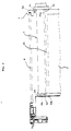
- the front board of the body 1 of the electrophotographic copying apparatus that corresponds to the inside of the front cabinet 1a has a positioning means of the light-transmitting device 4, e.g., a hole 1b, above the photosensitive drum 2, which is extended in the longitudinal direction of the photosensitive drum 2.
- the light-transmitting device 4 can be installed into and removed from the body 1 of the electrophotographic copying apparatus 1 through the hole 1b.
- the light-transmitting device 4 has a fixed magnification.
- the light-transmitting device 4 with a certain magnification can be readily replaced by another light-transmitting device with a different magnification.
- the light-transmitting device 4 has positioning means, e.g., positioning pins 4a and 4b that can be engaged with positioning means, e.g., positioning holes 1c and 1d, respectively, of the body 1 of the electrophotographic copying apparatus, and positioning means, e.g., positioning pins 4c and 4d that can be engaged with positioning means, e.g., positioning holes 15a and 15b, respectively, of the first image-forming unit 15 to be mentioned below.
- positioning means e.g., positioning pins 4a and 4b that can be engaged with positioning means, e.g., positioning holes 1c and 1d, respectively, of the body 1 of the electrophotographic copying apparatus
- positioning means e.g., positioning pins 4c and 4d that can be engaged with positioning means, e.g., positioning holes 15a and 15b, respectively, of the first image-forming unit 15 to be mentioned below.
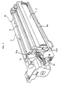
- Figure 4 shows the above-mentioned first image-forming unit 15 that comprises the photosensitive drum 2, the charging device 3, and the cleaning device 7 in the housing of the image-forming unit 15.
- the cleaning device 7 is provided with a used toner-ejection opening 7b that has a lid 7c.
- the used toner which has been recovered by the cleaning device 7 from the surface of the photosensitive drum 2, is conveyed from the cleaning device 7 to the ejection opening 7b of a conveyance portion of the first image-forming unit 15 by means of a conveyance means 7a ( Figure 1) such as a conveyance screw, and then ejected from the ejection opening 7b.
- a conveyance means 7a Figure 1 such as a conveyance screw
- the used toner is carried from the ejection opening 7b to the opening of a used toner-collecting tank 17 ( Figure 5) that is a part of the second image-forming unit 18 to be mentioned below.
- the housing of the first image-forming unit 15 is provided with a guiding portion 15c, in the longitudinal direction of the photosensitive drum 2, below the portion of the photosensitive drum 2 that is exposed to the outside of the housing of the first image-forming unit 15.
- the guiding portion 15c supports the second image-forming unit 18 in a manner to guide the second image-forming unit 18 to a given position of the body 1 of the electrophotographic copying apparatus when the second image-forming unit 18 is installed into the body 1 of the electrophotographic copying apparatus.
- the first image-forming unit 15 is provided with a positioning hole 15d that is engaged with a positioning boss 24 of the second image-forming unit 18.
- the first image-forming unit 15 is fixed to the body 1 of electrophotographic copying apparatus by means of a guide-supporting means (not shown) of the body 1 of the electrophotographic copying apparatus so that the first image-forming unit 15 can be freely installed into and removed from the body 1 of the electrophotographic copying apparatus, making it easy for the user to replace the said unit by another.
- the front cabinet 1a of the body 1 is opened and the light-transmitting device 4 is removed from the body 1, and thereafter the first image-forming unit 15 is removed from the body 1 of the electrophotographic copying apparatus.
- the first image-forming unit 15 is inserted into the body 1 of the electrophotographic copying apparatus along the above-mentioned guide-supporting means of the body 1 and the light-transmitting device 4 is then inserted into the body 1 along the hole 1b of the body 1 so as to fasten the positioning pins 4a and 4b of the light-transmitting device 4 into the positioning holes 1c and 1d of the body 1, so that the position of the light-transmitting device 4 with respect to the body 1 can be decided.
- the positioning pins 4c and 4d of the light-transmitting device 4 are engaged with the positioning holes 15a and 15b of the first image-forming unit 15, so that the position of the first image-forming unit 15 with respect to the light-transmitting device 4, (namely, the position of the first image-forming unit 15 with respect to the body 1 of the electrophotographic copying apparatus) can be decided.
- Figure 5 shows the above-mentioned second image-forming unit 18, which has a developing device 5 and a used toner-collecting tank 17.
- the developing device 5 has a cover 21 for covering a developing sleeve 20 ( Figure 1).
- the developing device 5 is provided with a label 22 that indicates the color of toner that is used for the formation of images.
- the indication of the label 22 can be seen through the window that is formed on the front cabinet 1a of the body 1 of the electrophotographic copying apparatus.
- a slidable shutter 23 is disposed on the used toner-collecting tank 17, a slidable shutter 23 is disposed.
- the shutter 23 is closed while the second image-forming unit 18 is being removed from the body 1 of the electrophotographic copying apparatus, so that leakages of the used toner from the tank 17 can be prevented.
- the shutter 23 is slid in the arrow direction to open while the second image-forming unit 18 is being installed into the body 1, so that the opening of the tank 17 faces the opening 7b ( Figure 4) of the cleaning device 7 of the first image-forming unit 15.
- the second image-forming unit 18 ( Figure 5) has a positioning boss 24 by which the position of the said second image-forming unit 18 with respect to the first image-forming unit 15 is fixed, a lock projection 25 by which the second image-forming unit 18 is fixed to the body 1 of the electrophotographic copying apparatus, and a grip 26 that the user grasps while the second image-forming unit 18 is being installed into the body 1 of the electrophotographic copying apparatus.
- the second image-forming unit 18 is installed into the body 1 of the electrophotographic copying apparatus as follows: First of all, the first image-forming unit 15 is installed in the body 1 of the electrophotographic copying apparatus. Then, the cover 21 of the second image-forming unit 18 is opened to expose a magnet brush that has been formed on the surface of the developing sleeve 20, and the second image-forming unit 18 is inserted into the body 1 of the electrophotographic copying apparatus along the guiding portion 15c of the first image-forming unit 15. Then, the positioning boss 24 of the second image-forming unit 18 is engaged with the positioning hole 15d of the first image-forming unit 15 so that the position of the second image-forming unit 18 with respect to the first image-forming unit 15 is precisely fixed.
- the second image-forming unit 18 is fixed to the body 1 of the electrophotographic copying apparatus by means of the locking projection 25 of the second image-forming unit 18.
- the same operation as mentioned above is performed in the reverse order.
- the guiding portion 15c and the positioning hole 15d of the first image-forming unit 15 function to fix the position of the second image-forming unit 18 with respect to the first image-forming unit 15, so that the position of the magnet brush, which has been formed on the surface of the developing sleeve 20, with respect to the surface of the photosensitive drum 2 can be fixed accurately.
- the second image-forming unit 18 with the developing device 5 is only replaced by another one. In this way, because the replacement of both the first image-forming unit 15 and the light-transmitting device 4 is unnecessary even when a copying operation with a colored toner different from that of the previous copying operation is needed, such a copying operation can be readily performed.
Landscapes
- Physics & Mathematics (AREA)
- General Physics & Mathematics (AREA)
- Engineering & Computer Science (AREA)
- Computer Vision & Pattern Recognition (AREA)
- Electrophotography Configuration And Component (AREA)
- Exposure Or Original Feeding In Electrophotography (AREA)
- Discharging, Photosensitive Material Shape In Electrophotography (AREA)
Applications Claiming Priority (2)
| Application Number | Priority Date | Filing Date | Title |
|---|---|---|---|
| JP62307125A JPH067277B2 (ja) | 1987-12-04 | 1987-12-04 | 電子写真装置 |
| JP307125/87 | 1987-12-04 |
Publications (3)
| Publication Number | Publication Date |
|---|---|
| EP0319340A2 true EP0319340A2 (fr) | 1989-06-07 |
| EP0319340A3 EP0319340A3 (en) | 1990-09-05 |
| EP0319340B1 EP0319340B1 (fr) | 1993-07-28 |
Family
ID=17965333
Family Applications (1)
| Application Number | Title | Priority Date | Filing Date |
|---|---|---|---|
| EP88311483A Expired - Lifetime EP0319340B1 (fr) | 1987-12-04 | 1988-12-02 | Appareil à copier électrophotographique |
Country Status (4)
| Country | Link |
|---|---|
| US (1) | US4963928A (fr) |
| EP (1) | EP0319340B1 (fr) |
| JP (1) | JPH067277B2 (fr) |
| DE (1) | DE3882666T2 (fr) |
Families Citing this family (9)
| Publication number | Priority date | Publication date | Assignee | Title |
|---|---|---|---|---|
| JPH03210581A (ja) * | 1990-01-16 | 1991-09-13 | Alps Electric Co Ltd | 電子写真装置 |
| US5182595A (en) * | 1990-07-26 | 1993-01-26 | Konica Corporation | Image forming apparatus having an dismountable process cartridge |
| DE69219119T2 (de) * | 1992-06-30 | 1997-10-02 | Canon Kk | Prozesseinheit und Bilderzeugungssystem für eine solche Prozesseneinheit |
| CA2105252C (fr) * | 1992-09-01 | 1999-11-16 | Michihisa Iguchi | Unite de traitement amovible pour un dispositif electrophotographique |
| USD553183S1 (en) * | 2004-02-13 | 2007-10-16 | Konica Minolta Business Technologies, Inc. | Developing device with a toner container |
| USD552671S1 (en) * | 2004-08-05 | 2007-10-09 | Konica Minolta Business Technologies, Inc. | Portion of a toner container |
| USD546382S1 (en) * | 2005-06-02 | 2007-07-10 | Samsung Electronics Co., Ltd. | Toner cartridge for printer |
| USD587303S1 (en) * | 2006-12-13 | 2009-02-24 | Samsung Electronics Co., Ltd. | Toner cartridge |
| JP6187294B2 (ja) * | 2014-02-12 | 2017-08-30 | 富士ゼロックス株式会社 | 画像形成装置 |
Family Cites Families (8)
| Publication number | Priority date | Publication date | Assignee | Title |
|---|---|---|---|---|
| JPS54116944A (en) * | 1978-03-03 | 1979-09-11 | Canon Inc | Positioning method of array of elements of short focal length and small focal point |
| JPS58139162A (ja) * | 1982-02-12 | 1983-08-18 | Canon Inc | プロセスキツト及びこのキツトを用いる像形成装置 |
| JPS58143355A (ja) * | 1982-02-19 | 1983-08-25 | Matsushita Electric Ind Co Ltd | 電子写真複写機 |
| US4632536A (en) * | 1983-10-11 | 1986-12-30 | Canon Kabushiki Kaisha | Copying apparatus and an optical assembly usable therewith |
| JPH0697326B2 (ja) * | 1984-02-07 | 1994-11-30 | 三田工業株式会社 | ユニット型複写機 |
| JPS6156657U (fr) * | 1984-09-20 | 1986-04-16 | ||
| US4653894A (en) * | 1986-01-15 | 1987-03-31 | Xerox Corporation | Fiber lens array mounting in reproduction machines |
| JPS62272283A (ja) * | 1986-05-20 | 1987-11-26 | Sharp Corp | 画像形成装置 |
-
1987
- 1987-12-04 JP JP62307125A patent/JPH067277B2/ja not_active Expired - Fee Related
-
1988
- 1988-12-02 EP EP88311483A patent/EP0319340B1/fr not_active Expired - Lifetime
- 1988-12-02 DE DE88311483T patent/DE3882666T2/de not_active Expired - Lifetime
- 1988-12-02 US US07/279,413 patent/US4963928A/en not_active Expired - Lifetime
Also Published As
| Publication number | Publication date |
|---|---|
| EP0319340A3 (en) | 1990-09-05 |
| JPH01147555A (ja) | 1989-06-09 |
| EP0319340B1 (fr) | 1993-07-28 |
| DE3882666T2 (de) | 1993-12-16 |
| DE3882666D1 (de) | 1993-09-02 |
| JPH067277B2 (ja) | 1994-01-26 |
| US4963928A (en) | 1990-10-16 |
Similar Documents
| Publication | Publication Date | Title |
|---|---|---|
| EP0276910B1 (fr) | Unité de traitement et appareil de formation d'image en couleur l'utilisant | |
| US5337134A (en) | Sheet inverting unit and an imaging forming apparatus employing the same | |
| KR940003109B1 (ko) | 화상 기록장치 | |
| EP0255713A2 (fr) | Appareil électrographique | |
| JP3181805B2 (ja) | デジタル画像形成装置 | |
| US4963928A (en) | Electrophotographic copying apparatus equipped with positioning device | |
| JPS62272283A (ja) | 画像形成装置 | |
| US5087932A (en) | Electrophotographic image forming terminal having an improved arrangement of electrical parts | |
| EP0784241A2 (fr) | Appareil de formation d'images | |
| JP3608767B2 (ja) | 画像形成装置 | |
| EP0230033A2 (fr) | Cartouche pour utilisation dans un appareil de tirage d'images | |
| US4882605A (en) | Electrophotographic copying machine | |
| US5245394A (en) | Image forming apparatus having an openable conveyance path | |
| JPS59147377A (ja) | プロセスカートリッジ及びプロセスカートリッジを装着可能な画像形成装置 | |
| JP2822068B2 (ja) | カラー画像形成装置 | |
| JPH06194892A (ja) | プロセスカートリッジおよび画像形成装置 | |
| JP3048167B2 (ja) | 画像形成装置 | |
| JPS60104960A (ja) | プロセスユニット及び前記プロセスユニットを装着可能な画像形成装置 | |
| JPH01251072A (ja) | 画像形成装置 | |
| JP2826665B2 (ja) | カラー画像形成装置 | |
| JPH01251037A (ja) | 画像形成装置 | |
| JPS5984260A (ja) | 画像形成装置 | |
| JP3296123B2 (ja) | 電子写真装置 | |
| JPS62226164A (ja) | 画像形成装置 | |
| JPH01161368A (ja) | プロセスカートリツジを適用した画像形成装置 |
Legal Events
| Date | Code | Title | Description |
|---|---|---|---|
| PUAI | Public reference made under article 153(3) epc to a published international application that has entered the european phase |
Free format text: ORIGINAL CODE: 0009012 |
|
| 17P | Request for examination filed |
Effective date: 19881208 |
|
| AK | Designated contracting states |
Kind code of ref document: A2 Designated state(s): DE FR GB |
|
| PUAL | Search report despatched |
Free format text: ORIGINAL CODE: 0009013 |
|
| AK | Designated contracting states |
Kind code of ref document: A3 Designated state(s): DE FR GB |
|
| 17Q | First examination report despatched |
Effective date: 19920303 |
|
| GRAA | (expected) grant |
Free format text: ORIGINAL CODE: 0009210 |
|
| AK | Designated contracting states |
Kind code of ref document: B1 Designated state(s): DE FR GB |
|
| REF | Corresponds to: |
Ref document number: 3882666 Country of ref document: DE Date of ref document: 19930902 |
|
| ET | Fr: translation filed | ||
| PLBE | No opposition filed within time limit |
Free format text: ORIGINAL CODE: 0009261 |
|
| STAA | Information on the status of an ep patent application or granted ep patent |
Free format text: STATUS: NO OPPOSITION FILED WITHIN TIME LIMIT |
|
| 26N | No opposition filed | ||
| REG | Reference to a national code |
Ref country code: GB Ref legal event code: IF02 |
|
| PGFP | Annual fee paid to national office [announced via postgrant information from national office to epo] |
Ref country code: GB Payment date: 20071128 Year of fee payment: 20 Ref country code: FR Payment date: 20071210 Year of fee payment: 20 |
|
| PGFP | Annual fee paid to national office [announced via postgrant information from national office to epo] |
Ref country code: DE Payment date: 20071129 Year of fee payment: 20 |
|
| REG | Reference to a national code |
Ref country code: GB Ref legal event code: PE20 Expiry date: 20081201 |
|
| PG25 | Lapsed in a contracting state [announced via postgrant information from national office to epo] |
Ref country code: GB Free format text: LAPSE BECAUSE OF EXPIRATION OF PROTECTION Effective date: 20081201 |