EP0784241A2 - Appareil de formation d'images - Google Patents
Appareil de formation d'images Download PDFInfo
- Publication number
- EP0784241A2 EP0784241A2 EP97300082A EP97300082A EP0784241A2 EP 0784241 A2 EP0784241 A2 EP 0784241A2 EP 97300082 A EP97300082 A EP 97300082A EP 97300082 A EP97300082 A EP 97300082A EP 0784241 A2 EP0784241 A2 EP 0784241A2
- Authority
- EP
- European Patent Office
- Prior art keywords
- image forming
- forming apparatus
- information
- image
- high voltage
- Prior art date
- Legal status (The legal status is an assumption and is not a legal conclusion. Google has not performed a legal analysis and makes no representation as to the accuracy of the status listed.)
- Withdrawn
Links
Images




Classifications
-
- G—PHYSICS
- G03—PHOTOGRAPHY; CINEMATOGRAPHY; ANALOGOUS TECHNIQUES USING WAVES OTHER THAN OPTICAL WAVES; ELECTROGRAPHY; HOLOGRAPHY
- G03G—ELECTROGRAPHY; ELECTROPHOTOGRAPHY; MAGNETOGRAPHY
- G03G21/00—Arrangements not provided for by groups G03G13/00 - G03G19/00, e.g. cleaning, elimination of residual charge
- G03G21/16—Mechanical means for facilitating the maintenance of the apparatus, e.g. modular arrangements
- G03G21/18—Mechanical means for facilitating the maintenance of the apparatus, e.g. modular arrangements using a processing cartridge, whereby the process cartridge comprises at least two image processing means in a single unit
- G03G21/1875—Mechanical means for facilitating the maintenance of the apparatus, e.g. modular arrangements using a processing cartridge, whereby the process cartridge comprises at least two image processing means in a single unit provided with identifying means or means for storing process- or use parameters, e.g. lifetime of the cartridge
- G03G21/1878—Electronically readable memory
- G03G21/1882—Electronically readable memory details of the communication with memory, e.g. wireless communication, protocols
- G03G21/1885—Electronically readable memory details of the communication with memory, e.g. wireless communication, protocols position of the memory; memory housings; electrodes
-
- G—PHYSICS
- G03—PHOTOGRAPHY; CINEMATOGRAPHY; ANALOGOUS TECHNIQUES USING WAVES OTHER THAN OPTICAL WAVES; ELECTROGRAPHY; HOLOGRAPHY
- G03G—ELECTROGRAPHY; ELECTROPHOTOGRAPHY; MAGNETOGRAPHY
- G03G15/00—Apparatus for electrographic processes using a charge pattern
- G03G15/50—Machine control of apparatus for electrographic processes using a charge pattern, e.g. regulating differents parts of the machine, multimode copiers, microprocessor control
-
- G—PHYSICS
- G03—PHOTOGRAPHY; CINEMATOGRAPHY; ANALOGOUS TECHNIQUES USING WAVES OTHER THAN OPTICAL WAVES; ELECTROGRAPHY; HOLOGRAPHY
- G03G—ELECTROGRAPHY; ELECTROPHOTOGRAPHY; MAGNETOGRAPHY
- G03G2221/00—Processes not provided for by group G03G2215/00, e.g. cleaning or residual charge elimination
- G03G2221/16—Mechanical means for facilitating the maintenance of the apparatus, e.g. modular arrangements and complete machine concepts
- G03G2221/1663—Mechanical means for facilitating the maintenance of the apparatus, e.g. modular arrangements and complete machine concepts having lifetime indicators
-
- G—PHYSICS
- G03—PHOTOGRAPHY; CINEMATOGRAPHY; ANALOGOUS TECHNIQUES USING WAVES OTHER THAN OPTICAL WAVES; ELECTROGRAPHY; HOLOGRAPHY
- G03G—ELECTROGRAPHY; ELECTROPHOTOGRAPHY; MAGNETOGRAPHY
- G03G2221/00—Processes not provided for by group G03G2215/00, e.g. cleaning or residual charge elimination
- G03G2221/16—Mechanical means for facilitating the maintenance of the apparatus, e.g. modular arrangements and complete machine concepts
- G03G2221/18—Cartridge systems
- G03G2221/1823—Cartridges having electronically readable memory
-
- G—PHYSICS
- G03—PHOTOGRAPHY; CINEMATOGRAPHY; ANALOGOUS TECHNIQUES USING WAVES OTHER THAN OPTICAL WAVES; ELECTROGRAPHY; HOLOGRAPHY
- G03G—ELECTROGRAPHY; ELECTROPHOTOGRAPHY; MAGNETOGRAPHY
- G03G2221/00—Processes not provided for by group G03G2215/00, e.g. cleaning or residual charge elimination
- G03G2221/16—Mechanical means for facilitating the maintenance of the apparatus, e.g. modular arrangements and complete machine concepts
- G03G2221/18—Cartridge systems
- G03G2221/183—Process cartridge
Definitions
- the present invention relates to an image forming apparatus such as a copying machine or a printer.
- an image forming apparatus comprising a storing means for information, such as print count, data for controlling processing devices within the image forming apparatus, and the like, which are related to image formation.
- Japanese Laid-Open Patent Application No. 61854/1984 discloses an image forming apparatus comprising a storing means for storing the information related to image formation.
- a non-volatile RAM is mounted in a process cartridge, and the amount of process cartridge usage in the main assembly of the image forming apparatus is stored in this non-volatile RAM.
- the stored information is used to determine the limit for the process cartridge, so that a user can be informed of process cartridge replacement timing.
- Japanese Laid-Open Patent Application No. 149051/1994 proposes an additional usage of the non-volatile RAM to protect the main assembly of the image forming apparatus. More specifically, a quality code is stored in the non-volatile RAM, and image formation is rendered impossible unless the quality code on the apparatus main assembly side matches the quality code stored in the non-volatile RAM of a process cartridge.
- information is accurately exchanged between the storage medium mounted in a process cartridge, and an image forming apparatus, wherein the exchanged information is used to improve the functions of the process cartridge and the image forming apparatus.
- the information exchange between the storage medium mounted in a process cartridge, and an information inputting/outputting means mounted in an image forming apparatus to exchange information with the storage medium of the process cartridge, is dependent on an extremely weak information signal such as electric current in the order of ⁇ m A. This cannot be avoided regardless of the type of the storage medium mounted in a process cartridge, as long as the control information, the status information, and the like within the main assembly of an image forming apparatus are transmitted using weak electric current.
- a high voltage electric power source is mounted in an image forming apparatus.
- a high voltage electric power source in particular, an AC power source for generating an AC voltage comprising an oscillating component, is in operation, noises are frequently generated.
- a shield is placed in a manner to surround a high voltage electric power source and the peripheral circuit thereof.
- a substantially thick member is placed at a location which is a proper distance away from the high voltage power source.
- a shield along the information signal transmission path is also effective for preventing the noise interference to the information signal.
- a portion of the aforementioned information signal transmission path must be constituted of a connector, a sliding electrode, or the like, and it is rather difficult to effectively shield this portion.
- a countermeasure such as employing a shielded connector for connecting a personal computer to its peripheral devices, must be taken. The employment of such a connected is expected to increase the apparatus cost enormously.
- the present invention was made in consideration of the problem described above, and its primary object is to provide an image forming apparatus in which the noise generating from a high voltage electric power source does not interfere with an information signal exchanged between an information storing means and an information inputting/outputting means.
- Another object of the present invention is to provide an image forming apparatus which is low in the counter-noise measure cost.
- an image forming apparatus comprises: image forming means for forming an image on a recording material; a high voltage electric power source for driving said image forming means; storing means for storing information related to image formation; and information inputting/outputting means for inputting the information into the storing means, or outputting it therefrom, by accessing the storing means, wherein the inputting/outputting means accesses the storing means means when the high voltage electric power source is not in operation.
- Figure 1 is a flow chart showing the control flow for continuous image formation.
- Figure 2 is a sectional view of the image forming apparatus in a preferred embodiment of the present invention, depicting the general structure thereof.
- Figure 3 is a sectional view of a process cartridge compatible with the image forming apparatus in the preferred embodiment, depicting the general structure thereof.
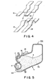
- Figure 4 is a perspective view of an information transmission contact point.
- Figure 5 is a sectional view of a developing apparatus compatible with the image forming apparatus in the second embodiment of the present invention, depicting the general structure thereof.
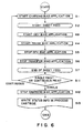
- Figure 6 is a flow chart for the third embodiment of the present invention, showing the control flow for continuous image formation.
- Figure 7 is a sectional view of the image forming apparatus in the third embodiment of the present invention, depicting the general structure thereof.
- Figure 8 is a flow chart for the fourth embodiment of the present invention, depicting the control flow for continuous image formation.
- Figure 9 is a sectional view of the image forming apparatus in the fifth embodiment of the present invention.
- a photosensitive drum 1 is surrounded by a charge roller 2 as a contact type charging means, a development roller 3 as a developer carrying member, a transfer roller 10, a cleaning blade 12 as a cleaning means for removing the residual toner from the photosensitive drum 1.
- the development roller 3 is formed of a piece of aluminum pipe or the like.
- the photosensitive drum 1, the charge roller 2, the developing apparatus 5, and the elastic cleaning blade 12 as the cleaning means are integrally united. These components such as the photosensitive drum 1 are positioned in the process cartridge 14 so that their positional relationship among them meets predetermined specific requirements. For example, the process cartridge 14 must be inserted into, or removed from, a predetermined section (accommodating means 40) within the main assembly of the image forming apparatus, following a predetermined procedure.
- a predetermined section accommodating means 40
- the process cartridge 14 in this embodiment is characterized in that it comprises a storage medium 15 into which optional information can be inputted from the main assembly of an image forming apparatus, and from which the optional information can be read by the main assembly of the image forming apparatus, wherein control is executed in such a manner that information is inputted into the storage medium 15, or outputted therefrom, only when the high voltage electric power source mounted in the main assembly of the image forming apparatus is not in operation.
- a non-volatile RAM with a storage capacity of 2 K bytes is employed as the storage medium 15.
- the storage medium 15 may be constituted of other storage medium such as magnetic storage medium or optical storage medium.
- the content to be stored in the storage medium 15 is information depicting the condition of the image forming apparatus.
- the toner 4 in the toner containing portion 5a is conveyed to the surface of the photosensitive drum 1. During this conveyance, the toner 4 is regulated in its thickness and also is charged, by the development roller 3 rotating in the direction of the arrow mark R1 in Figure 2, and the elastic blade 7.
- the photosensitive drum 1 is rotated in the direction of the arrow mark R2 in Figure 2 at a peripheral velocity of 40 revolutions per minute while a bias voltage composed by superposing a DC voltage of -600V, and an AC voltage in the form of a sine wave having a peak-to-peak voltage of 1600 V and a frequency of 300 Hz is applied from the image forming apparatus main assembly side through a charge roller 2.
- a bias voltage composed by superposing a DC voltage of -600V, and an AC voltage in the form of a sine wave having a peak-to-peak voltage of 1600 V and a frequency of 300 Hz is applied from the image forming apparatus main assembly side through a charge roller 2.
- the surface of the photosensitive drum 1 is charged to approximately -600 V.
- a latent image is drawn on the charged photosensitive drum 1 by a beam of light projected from the laser beam projecting apparatus 9 provided on the image forming apparatus main assembly side.
- a bias voltage composed by superposing a DC voltage of -500 V and an AC voltage in the form of a sine wave having a peak-to-peak voltage of 1600 V and a frequency of 1700 Hz is applied to the development roller 3 from the high voltage electric power source 18 mounted on the image forming apparatus main assembly side.
- the toner 4 is caused to shuttle between the photosensitive drum 1 and the development roller 3.
- the actual potential at the surface of the photosensitive drum 1 is negative in both the light portion and the dark portion of the latent image, and the toner 4 adheres to the surface of the photosensitive drum 1, being distributed by the amount proportional to the potential; in other words, the latent image is developed.
- a recording sheet 12 as recording medium held in a sheet feeder cassette 20 is conveyed by a sheet feeder roller 31 and a conveying means, into the nip formed by the photosensitive drum 1 and a transfer roller 22.
- a DC bias of approximately +2 kV is applied to the back side of the recording sheet 12 from the high voltage electric power source 18, whereby the toner image is transferred onto the surface of the recording sheet 12.
- the recording sheet 12 is conveyed into the fixing device 23, in which a fixed image is completed on the recording sheet 12.
- the toner 4 remaining on the photosensitive drum 1 after image transfer is scraped off by the cleaning blade 12 before the photosensitive drum 1 is charged next time.
- the scraped toner 4 is collected in a waste toner container 13.
- the information regarding the image forming apparatus condition is inputted into the storage medium 15 of the process cartridge 14 through an information transmission contact point 16.
- a simple sliding electrode 16 shown in Figure 4 which is not equipped with a special shield is employed as the information transmission contact point.
- an image forming apparatus comprising the process cartridge 14 in this embodiment carries out steps of applying a charge bias (S1), conveying the recording sheet (S2), applying a development bias (S3), and applying a transfer bias (S4), in this order, and then, stops applying the charge bias (S8) after stopping the application of the development bias (S5), stopping the application of the transfer bias (S6), and completing the recording sheet conveyance (S7). Thereafter, the information regarding the condition of the image forming apparatus is written into the storage medium 15 of the process cartridge 14 for the first time (S9). Next, a decision is made as to whether or not printing is to be continued (S10). When it is determined that printing is to be continued, the charge bias is applied again to charge the surface of the photosensitive drum 1, preparing it for the following image formation.
- the process cartridge 14 in this embodiment since the information concerning the condition of the image forming apparatus is inputted into the storage medium 15 of the process cartridge 14 when the high voltage electric power source 18, which is the main source of the noise, is not in operation, the weak signal used for information transmission is not subjected to the interference from the noise. Therefore, there is no need for the noise interference preventing means to be disposed along the information transmission path between the storage medium 15 and the information inputting/outputting means mounted in the image forming apparatus. Thus, it is possible to provide an inexpensive yet highly functional process cartridge, and an image forming apparatus comprising such a process cartridge.
- Figure 5 depicts another embodiment of the present invention, that is, a developing apparatus 14A in the form of a cartridge.
- a developer carrier member 3 like a development roller, and a developing means 5 comprising a developer (toner) storage portion 5a for containing toner 4 to be supplied to the developer carrier member 3, are integrally disposed in a plastic frame 50.
- the developing apparatus 14A in this embodiment may be considered to be substantially the same process cartridge as the process cartridge 14 described in the first embodiment, except for the absence of the photosensitive drum 1,
- the structures and functions of the toner storage portion 5a and the like in this embodiment are identical to those in the first embodiment, and are designated with the same referential symbols as those in the first embodiment, in order to substitute the descriptions in the first embodiment for the descriptions for those in this embodiment.
- the image forming apparatus in this embodiment is such an image forming apparatus that removably comprises the process cartridge in the first embodiment to carry out an image forming operation. It is characterized in that it comprises a means 17 for inputting information into the storage medium 15 of the process cartridge 14, or output it therefrom, wherein it is controlled in such a manner that information is inputted into the storage medium 15, or outputted therefrom, only when the high voltage 18 mounted in the image forming apparatus main assembly is not in operation.
- the image forming apparatus in this embodiment comprises a high voltage electric power source 18 for bias application, a laser scanner 9 for the formation of a charged latent image, a CPU 19, and a control ROM 21. Also, on the premise that in order to form an image, the process cartridge 14 in the first embodiment must be installed in the image forming apparatus main assembly, a sheet feeder cassette 20 for storing a recording sheet 12 as recording medium, a transfer roller 22 for transferring a toner image onto the recording sheet 12, and a fixing device 23 for fixing the toner image to the recording sheet 12 are properly positioned in the image forming apparatus.
- the CPU 19 controls an image formation sequence comprising bias application, recording sheet conveyance, and the like, on the basis of the control information stored in the control ROM 21.
- the content to be stored in the storage medium 15 is such information that depicts the condition of the image forming apparatus.
- the information regarding the condition of the image forming apparatus is inputted into the storage medium 15 mounted in the process cartridge 14 by the information inputting/outputting means 17, through a simple information transmission contact point 16 illustrated in Figure 4.
- This information transmission contact point 16 makes contact with the contact point provided on the process cartridge 14 side, with a predetermined contact pressure, as the process cartridge 14 is installed into the main assembly of the image forming apparatus.
- the image forming apparatus in this embodiment carries out the steps of applying a charge bias (S1) to completing the recording sheet conveyance (S7) in the same manner as the image forming apparatus in the first embodiment. Thereafter, it makes a decision as to whether or not printing is to be continued (S11). When it determines that printing is not to be continued, it stops the charge bias application (S12), and writes the information regarding the apparatus condition into the storage medium 15 for the first time (S13).
- the image forming apparatus in this embodiment is controlled by the CPU 19 in such a manner that the information concerning the condition of the image forming apparatus is inputted into the storage medium 15 of the process cartridge 14 for the first time after continuous printing of a predetermined number of copies is completed, and the application of the charge bias, the development bias, and the transfer bias is stopped.
- the CPU 19 issues again an instruction for applying the charge bias, so that the surface of the photosensitive drum 1 is charged to be prepared for the following image formation.
- the information depicting the condition of the image forming apparatus is inputted in the storage medium 15 when the high voltage electric power source, which is the main source of the noise in the image forming apparatus, is not in operation, the weak signal used for information transmission is not subjected to the interference from the noise. Therefore, it is possible to improve reliability in inputting information into the storage medium 15, or outputting it therefrom.
- the image forming apparatus is a such an image forming apparatus that removably employs the process cartridge 14 in the first embodiment to carry out an image forming operation. It is characterized in that it comprising a means 17 for inputting information into the storage medium 15 of the process cartridge 14 and outputting it therefrom, and an auxiliary storing means 24, wherein control is executed in such a manner that information is temporarily stored in the auxiliary storing means 24 when the high voltage electric power source 18 mounted in the image forming apparatus main assembly is in operation, and the information is inputted into the storage medium 15 of the process cartridge 14 from the auxiliary storing means 24, or outputted therefrom, when the high voltage electric power source 18 is not in operation.
- the image forming apparatus in this embodiment comprises the high voltage electric power source 18 for bias application, a laser beam projecting apparatus 9 for the formation of a charged latent image, a CPU 19, a control ROM 21, an RAM 24 as the auxiliary storing means, and a means 25 for inputting information into the RAM 24, and outputting it therefrom.
- a sheet feeder cassette 20 for holding a recording sheet 12 as recording medium, a transfer roller 22 for transferring a toner image onto the recording sheet 12, and a fixing device 23 for fixing the toner image to the recording sheet 12 are properly positioned, on the premise that in order to carry out an image forming operation, the process cartridge 14 in the first embodiment must be installed in the apparatus main assembly.
- the CPU 19 controls the image formation sequence comprising bias application, recording sheet conveyance, and the like, on the basis of the control information stored in the control ROM 21.
- the inputting/outputting means 25 for exchanging information between the CPU 19 and the RAM 24 is disposed in a shield case 26 formed of 0.5 mm thick stainless steel, so that the information signal is rendered less liable to be affected by the noise which occurs when the high voltage electric power source 18 is in operation.
- the content to be stored in the storage medium 15 is the information about the print count for the image forming apparatus.
- the information regarding the print count is inputted into the storage medium 15 mounted in the process cartridge 14 by the information inputting/outputting means 17, through a simple information transmission contact point 16 illustrated in Figure 9.
- This information transmission contact point 16 makes contact with the contact point provided on the process cartridge 14 side, with a predetermined contact pressure, as the process cartridge 14 is installed into the main assembly of the image forming apparatus.
- the image forming apparatus in this embodiment carries out image forming processes such as applying a charge bias (S31), conveying a recording sheet (S32), applying a development bias (S33), applying a transfer bias (S34), in this order, and then, writes the print count information into the RAM 24 as the auxiliary storage medium (S35).
- S39 On it determines that printing is not to be continued, it stops the charge bias application (S40). Then, it writes the information about the print count into the storage medium 15 of the process cartridge 14 from the RAM 24 of the apparatus main assembly.
- the charge bias is applied again to charge the surface of the photosensitive drum 1, preparing it for the following image formation.
- the weak signal used for information transmission is not subjected to the interference from the noise.
- the image forming apparatus in this embodiment is effective to increase the image formation speed while maintaining reliability in information transmission when it is necessary to store such information that changes for each print.
- process cartridge in the third of fourth embodiment is compatible with the developing apparatus in the second embodiment.
Landscapes
- Engineering & Computer Science (AREA)
- Physics & Mathematics (AREA)
- General Physics & Mathematics (AREA)
- Microelectronics & Electronic Packaging (AREA)
- Computer Networks & Wireless Communication (AREA)
- Computer Vision & Pattern Recognition (AREA)
- Electrophotography Configuration And Component (AREA)
- Control Or Security For Electrophotography (AREA)
- Dry Development In Electrophotography (AREA)
Applications Claiming Priority (2)
| Application Number | Priority Date | Filing Date | Title |
|---|---|---|---|
| JP18092/96 | 1996-01-09 | ||
| JP8018092A JPH09190139A (ja) | 1996-01-09 | 1996-01-09 | プロセスカートリッジ、現像装置及び電子写真画像形成装置 |
Publications (2)
| Publication Number | Publication Date |
|---|---|
| EP0784241A2 true EP0784241A2 (fr) | 1997-07-16 |
| EP0784241A3 EP0784241A3 (fr) | 1998-12-16 |
Family
ID=11961998
Family Applications (1)
| Application Number | Title | Priority Date | Filing Date |
|---|---|---|---|
| EP97300082A Withdrawn EP0784241A3 (fr) | 1996-01-09 | 1997-01-08 | Appareil de formation d'images |
Country Status (3)
| Country | Link |
|---|---|
| US (1) | US5926665A (fr) |
| EP (1) | EP0784241A3 (fr) |
| JP (1) | JPH09190139A (fr) |
Cited By (1)
| Publication number | Priority date | Publication date | Assignee | Title |
|---|---|---|---|---|
| EP0997785A1 (fr) * | 1998-10-30 | 2000-05-03 | Canon Kabushiki Kaisha | Elément photosensible électrophotographique et appareil de production d'image le comprenant |
Families Citing this family (11)
| Publication number | Priority date | Publication date | Assignee | Title |
|---|---|---|---|---|
| JP3780087B2 (ja) * | 1998-02-16 | 2006-05-31 | キヤノン株式会社 | 画像記録装置 |
| US6658219B1 (en) * | 1999-09-30 | 2003-12-02 | Fuji Photo Film Co., Ltd. | Method, device, system and recording medium for detecting improper cartridge, and cartridge |
| JP2002062780A (ja) * | 2000-08-16 | 2002-02-28 | Canon Inc | 画像形成装置および方法 |
| US6694106B2 (en) * | 2001-02-19 | 2004-02-17 | Canon Kabushiki Kaisha | Image processing apparatus, a unit used in the apparatus, and a memory device mounted on the unit |
| JP3994968B2 (ja) | 2002-04-16 | 2007-10-24 | セイコーエプソン株式会社 | 画像形成装置、現像ユニット、及び、コンピュータシステム |
| EP1496402A4 (fr) * | 2002-04-16 | 2010-07-07 | Seiko Epson Corp | Dispositif de formation d'image, unite de mise au point et systeme informatique |
| JP4194298B2 (ja) * | 2002-05-17 | 2008-12-10 | キヤノン株式会社 | 情報記憶媒体、ユニット、プロセスカートリッジ、現像カートリッジおよび電子写真画像形成装置 |
| KR100649804B1 (ko) * | 2002-05-21 | 2006-11-27 | 세이코 엡슨 가부시키가이샤 | 화상 형성 장치 및 컴퓨터 시스템 |
| US9296214B2 (en) | 2004-07-02 | 2016-03-29 | Zih Corp. | Thermal print head usage monitor and method for using the monitor |
| JP4613560B2 (ja) * | 2004-09-22 | 2011-01-19 | 富士ゼロックス株式会社 | 画像形成装置およびカートリッジ |
| US8721203B2 (en) | 2005-10-06 | 2014-05-13 | Zih Corp. | Memory system and method for consumables of a printer |
Family Cites Families (12)
| Publication number | Priority date | Publication date | Assignee | Title |
|---|---|---|---|---|
| US35751A (en) * | 1862-07-01 | Improved metallic heel for boots or shoes | ||
| US4111544A (en) * | 1976-04-15 | 1978-09-05 | Xerox Corporation | Apparatus and method for noise immunity for control signals in electrostatographic processing machines |
| JPS5961854A (ja) * | 1982-09-30 | 1984-04-09 | Canon Inc | プロセスカ−トリツジ及びこのカ−トリツジを使用する画像形成装置 |
| US4961088A (en) * | 1989-04-20 | 1990-10-02 | Xerox Corporation | Monitor/warranty system for electrostatographic reproducing machines using replaceable cartridges |
| GB2234467B (en) * | 1989-07-04 | 1993-06-16 | Ricoh Kk | Image forming apparatus with replaceable process units. |
| JPH03216666A (ja) * | 1990-01-22 | 1991-09-24 | Ricoh Co Ltd | 電子写真装置 |
| US5101233A (en) * | 1990-02-15 | 1992-03-31 | Oki Electric Industry Co., Ltd. | Electrophotographic recording apparatus indicating a wear rate for consumable parts |
| US5034770A (en) * | 1990-08-30 | 1991-07-23 | Xerox Corporation | Job integrity and security apparatus |
| JPH0675442A (ja) * | 1992-08-27 | 1994-03-18 | Minolta Camera Co Ltd | 画像形成装置 |
| JPH06149051A (ja) * | 1992-11-08 | 1994-05-27 | Ricoh Co Ltd | 現像剤収容器、プロセスカートリッジ、該容器又は該カートリッジの再利用判定装置及び画像形成装置 |
| US5283613A (en) | 1993-02-19 | 1994-02-01 | Xerox Corporation | Monitoring system with dual memory for electrophotographic printing machines using replaceable cartridges |
| JPH07281564A (ja) * | 1994-04-12 | 1995-10-27 | Fuji Xerox Co Ltd | カートリッジ寿命の検知方法 |
-
1996
- 1996-01-09 JP JP8018092A patent/JPH09190139A/ja active Pending
-
1997
- 1997-01-08 US US08/780,682 patent/US5926665A/en not_active Expired - Fee Related
- 1997-01-08 EP EP97300082A patent/EP0784241A3/fr not_active Withdrawn
Cited By (1)
| Publication number | Priority date | Publication date | Assignee | Title |
|---|---|---|---|---|
| EP0997785A1 (fr) * | 1998-10-30 | 2000-05-03 | Canon Kabushiki Kaisha | Elément photosensible électrophotographique et appareil de production d'image le comprenant |
Also Published As
| Publication number | Publication date |
|---|---|
| EP0784241A3 (fr) | 1998-12-16 |
| JPH09190139A (ja) | 1997-07-22 |
| US5926665A (en) | 1999-07-20 |
Similar Documents
| Publication | Publication Date | Title |
|---|---|---|
| EP0400557B1 (fr) | Appareil de développement et cartouche de traitement l'utilisant | |
| JP3559630B2 (ja) | 画像形成装置 | |
| US6782222B2 (en) | Image forming apparatus and process cartridge mountable therein in which a gap exists between a main assembly antenna of the apparatus and a memory antenna of the process cartridge mounted thereon | |
| US20030103774A1 (en) | Memory member, unit, process cartridge and electrophotographic image forming apparatus | |
| JPH0243636B2 (fr) | ||
| US5926665A (en) | Image forming apparatus | |
| CA2285112A1 (fr) | Dispositif de formation d'images electrophotographiques, cartouche pour execution du processus, dispositif de developpement, contenant de fourniture de revelateur et element de mesure pour ce dernier | |
| US5848343A (en) | Electrophotographic image-forming apparatus with uniform toner usage control | |
| JP3029646B2 (ja) | 画像形成装置 | |
| US4757349A (en) | Cleaning device and process for use in image forming apparatus | |
| US5761590A (en) | Developing apparatus having a bias voltage supplied to a conductive blade | |
| US6947676B2 (en) | Image forming apparatus and controlling method therefor determining state use of cartridge | |
| JPH09160364A (ja) | 画像形成装置 | |
| JP2001100617A (ja) | プロセスカートリッジ及び電子写真画像形成装置 | |
| JP3015233B2 (ja) | 画像形成装置 | |
| US6427054B1 (en) | Image forming apparatus indicating the residue of toner and the deficiency of toner | |
| EP0319340A2 (fr) | Appareil à copier électrophotographique | |
| HK1001427A (en) | Image forming apparatus | |
| JP3200208B2 (ja) | プロセスカートリッジおよび画像形成装置 | |
| US9915892B2 (en) | Developing device, process cartridge, and image forming apparatus | |
| JP3194444B2 (ja) | 現像装置 | |
| JP2002062722A (ja) | 現像装置、プロセスカートリッジ、及び電子写真画像形成装置 | |
| JP2001194966A (ja) | 電子写真画像形成装置 | |
| JP3296123B2 (ja) | 電子写真装置 | |
| JP3234389B2 (ja) | 電子写真装置 |
Legal Events
| Date | Code | Title | Description |
|---|---|---|---|
| PUAI | Public reference made under article 153(3) epc to a published international application that has entered the european phase |
Free format text: ORIGINAL CODE: 0009012 |
|
| AK | Designated contracting states |
Kind code of ref document: A2 Designated state(s): DE FR GB IT |
|
| PUAL | Search report despatched |
Free format text: ORIGINAL CODE: 0009013 |
|
| AK | Designated contracting states |
Kind code of ref document: A3 Designated state(s): DE FR GB IT |
|
| 17P | Request for examination filed |
Effective date: 19990430 |
|
| 17Q | First examination report despatched |
Effective date: 20010921 |
|
| STAA | Information on the status of an ep patent application or granted ep patent |
Free format text: STATUS: THE APPLICATION HAS BEEN WITHDRAWN |
|
| 18W | Application withdrawn |
Effective date: 20091214 |
|
| REG | Reference to a national code |
Ref country code: HK Ref legal event code: WD Ref document number: 1001427 Country of ref document: HK |