EP0319342B1 - Appareil pour déplacer un objet submergé - Google Patents
Appareil pour déplacer un objet submergé Download PDFInfo
- Publication number
- EP0319342B1 EP0319342B1 EP88311485A EP88311485A EP0319342B1 EP 0319342 B1 EP0319342 B1 EP 0319342B1 EP 88311485 A EP88311485 A EP 88311485A EP 88311485 A EP88311485 A EP 88311485A EP 0319342 B1 EP0319342 B1 EP 0319342B1
- Authority
- EP
- European Patent Office
- Prior art keywords
- chamber
- flow
- water
- housing
- outlets
- Prior art date
- Legal status (The legal status is an assumption and is not a legal conclusion. Google has not performed a legal analysis and makes no representation as to the accuracy of the status listed.)
- Expired - Lifetime
Links
- XLYOFNOQVPJJNP-UHFFFAOYSA-N water Substances O XLYOFNOQVPJJNP-UHFFFAOYSA-N 0.000 claims abstract description 40
- 238000005192 partition Methods 0.000 claims abstract description 10
- 230000009182 swimming Effects 0.000 claims abstract description 7
- 238000004140 cleaning Methods 0.000 description 2
- BRUQQQPBMZOVGD-XFKAJCMBSA-N Oxycodone Chemical compound O=C([C@@H]1O2)CC[C@@]3(O)[C@H]4CC5=CC=C(OC)C2=C5[C@@]13CCN4C BRUQQQPBMZOVGD-XFKAJCMBSA-N 0.000 description 1
- 230000007423 decrease Effects 0.000 description 1
- 230000002401 inhibitory effect Effects 0.000 description 1
- 239000007788 liquid Substances 0.000 description 1
- 238000004519 manufacturing process Methods 0.000 description 1
Images
Classifications
-
- E—FIXED CONSTRUCTIONS
- E04—BUILDING
- E04H—BUILDINGS OR LIKE STRUCTURES FOR PARTICULAR PURPOSES; SWIMMING OR SPLASH BATHS OR POOLS; MASTS; FENCING; TENTS OR CANOPIES, IN GENERAL
- E04H4/00—Swimming or splash baths or pools
- E04H4/14—Parts, details or accessories not otherwise provided for
- E04H4/16—Parts, details or accessories not otherwise provided for specially adapted for cleaning
- E04H4/1681—Cleaning whips
Definitions
- This invention relates to a device for displacing an article in a liquid, in particular a swimming pool cleaner.
- US Patent 3,392,788 describes a swimming pool cleaner which operates by flagellation.
- flagellation devices have a flexible hose with nozzle at its end. Water under pressure is supplied to the hose and water flowing out of the nozzle causes the hose to move around in the pool, disturbing dirt and causing it to be suspended in the water.
- the device shown in US Patent 3,392,738 also has a transporter which has a short length of pipe that is aligned with the hose.
- the pipe has a nozzle at each end - one pointing forward and the other pointing backward.
- the pipe has within it a ball which is movable to close one or the other of the nozzles.
- the pipe is connected to the tube, intermediate its ends, by a short connector so that water supplied to the tube also flows into the pipe.
- the transporter will cause the hose to move forward or backward.
- the supply of water into the pipe is cyclically interrupted.
- the ball may move from one nozzle to the other and, if it does move, when water again flows into the pipe it will discharge from the other nozzle to that from which it discharged previously, thereby changing the direction in which the transporter moves the hose.
- US Patent 4,169,484 describes an automatic pool cleaner apparatus which has a head at the free end of a flexible hose to which water is supplied under pressure.
- the cleaning head has a central inlet to which the hose is connected and a pair of outlet jets on each side thereof.
- the jets point generally back in the direction of the hose so that the head is displaced away from the hose, pulling the hose with it.
- the jets are open at all times.
- US Patent 4,686,728 describes a further pool cleaner which has an internal buoyancy chamber that varies in size so that the cleaner descends in the pool until it reaches the bottom at which time the air chamber inside is enlarged so that the cleaner moves upwardly in the water. This motion is repeated.
- the cleaner has an internal tube with a piston therein. When the cleaner reaches the floor of the swimming pool the piston is moved to close off the tube and suction is created within the cleaner which causes the air chamber to increase in size. As the cleaner rises, the piston slowly drops and the air chamber decreases in size so that the cleaner again sinks in the water.
- a device for displacing a swimming pool cleaner in a body of water comprising: a housing defining a flow chamber and having an inlet for receiving a flow of pressurized water, and a plurality of outlets; jet defining means on said outlets for directing flows of water therefrom in different selected directions, thereby to develop thrust on said housing in different directions; flow directing means for intermittently directing the flow of water into the chamber; means for randomly closing and opening said outlets including at least one displaceable member in said chamber engageable with one of the outlets to block the flow of water therethrough, the number of displaceable members being at least one less than the number of outlets whereby at least one outlet is left open to develop thrust from that outlet; characterised in that the device includes means movable within the chamber for contacting the or each displaceable member and for disengaging the or each displaceable member from the outlets when flow is not directed into said chamber.
- the outlets may be arranged in a plurality of groups.
- the housing may then define a plurality of chambers, with each group of outlets being in communication with a different chamber.
- the chambers may be defined by partitions within the housing.
- the flow directing means may be linearly displaceable and may also be rotatably displaceable.
- the device may further include drive means responsive to the flow of pressurized water for rotating the flow directing means.
- the flow directing means may be an elongated hollow rod that is rotatable and slidably mounted in the partitions.
- the rod may have an open end positioned adjacent the inlet to receive the flow of water therefrom, and may have a plurality of outlet orifices around the rod in an annular series. Rotation of the rod will then vary the angular positions of these outlet orifices within the chambers.
- the drive means may comprise a water turbine around said open end of said rod.
- the jet defining means may include four jet nozzles that are positioned at oblique angles relative to the housing, two of said nozzles being inclined laterally outwardly and in the direction of one end of the housing, and two of the nozzles being inclined laterally outwardly and in the direction of the other end of the housing.
- the displaceable member is a ball.
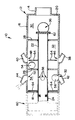
- a device for displacing a swimming pool cleaner is designated generally by reference numeral 10.
- the device 10 has a hollow housing 12 that has a connecting portion 14 at one end whereby it may be connected to a source of pressurized water (not shown). Further, the housing 12 has a cylindrical wall 16 with two end walls 18 and 20. The connecting portion projects from the end wall 20.
- the connecting portion 14 is centrally located and is aligned with a tube 22 that is slidable towards and away from the connecting portion 14.
- the tube 22 is axially connected to a further tube 24 at its end remote from the connecting portion 14, so that the tube 22 is rotatable relative to the tube 24.
- the further tube 24 extends through an opening in the end wall 18 and is slidable therein.
- the interior of the housing 12 is divided into three chambers by two annular partitions 26 and 28.
- a first chamber 30 which is located between the partition 28 and the end wall 20, a chamber 32 between the partitions 26 and 28 and a chamber 34 between the partition 26 and the end wall 18.
- An aperture 36 is provided in the cylindrical wall 16, in the region of the chamber 30, through which water may flow to perform a cleaning function.
- Four jet nozzles 38, 40, 42 and 44 are fast with the cylindrical wall 16, about openings 46, 48, 50 and 52, respectively.
- the nozzles 38 and 40 communicate with the chamber 32 and are directed in a backward direction
- the nozzles 42 and 44 communicate with the chamber 34 and are directed in a forward direction. All of the nozzles 38 to 44 are angled so that water issuing therefrom will exert a thrust on the housing 12 which has both a sideways component and a forward or backward component.
- the ball 54 seats in either the opening 46 or the opening 48 and the ball 56 seats in either the opening 50 or 52.
- the tube 22 has outlet orifices 58 through which water flows into either the chamber 34 or the chamber 32, depending on the position of the tube 22 which is displaced back and forth by the tube 24.
- the tube 24, in turn, is displaced backwards and forwards by a unit 60 which is shown in dotted lines and which does not form part of the present invention.
- the unit 60 is operated by water flow, which is supplied to it via the tube 24.
- the tube 22 has at its free end, ie. its end closest to the wall 20, a turbine wheel 62. It will be appreciated that when the tube 22 is at the limit of its stroke at which it is closest to the connecting portion 14, water flowing past the turbine wheel 62 will cause it to rotate, thereby rotating the tube 22. As the tube 22 is rotated slightly with each stroke, the relative orientation of the orifices 58 with reference to the openings 46 to 52 varies thereby inhibiting a particular pattern.
- the balls 54 and 56 close the openings 46 to 52 in a substantially random manner.
- the device 10 experiences an alternate forward and backward thrust, it also experiences a substantially random sideways thrust.
- the device 10 is moved forwards and backwards in a predetermined manner and randomly in a sideways manner.
- pins 64 are provided that are fast with the tube 22 and which dislodge the balls 54 and 56 upon movement of the tube 22.
- the invention provides a device whereby a pool cleaner may be displaced, which is cheap to manufacture, is reliable in operation and which moves in a predetermined but nonetheless random manner.
Landscapes
- Engineering & Computer Science (AREA)
- Architecture (AREA)
- Civil Engineering (AREA)
- Structural Engineering (AREA)
- Nozzles (AREA)
- Toys (AREA)
- Cleaning By Liquid Or Steam (AREA)
- Revetment (AREA)
- Load-Engaging Elements For Cranes (AREA)
- Motor Or Generator Frames (AREA)
- Cleaning In General (AREA)
- Transmission Devices (AREA)
Claims (13)
un corps (16) définissant une chambre d'écoulement de l'eau (32 ; 34) et équipé d'un orifice d'entrée (14) par lequel arrive l'eau sous pression et d'une pluralité d'orifices de sortie (46, 48 ; 50, 52) ;
des moyens de commande de l'alimentation prévus pour assurer, de façon intermittente, l'alimentation en eau (22 ; 58) de la chambre ;
des moyens pour fermer et ouvrir, de façon aléatoire, les dits orifices de sortie, (46, 48 ; 50, 52) comportant, au minimum, un élément déplaçable (54, 56) dans la dite chambre (32, 34), susceptible d'obturer l'un des orifices de sortie (46, 48 ; 50, 52) pour interrompre l'écoulement de l'eau à travers ce dernier, le nombre d'éléments déplaçables (54 ; 56) étant toujours inférieur, d'au moins une unité, au nombre total d'orifices de sortie (46, 48 ; 50, 52), ce grâce à quoi au moins un orifice de sortie est laissé ouvert pour développer une poussée à partir de cet orifice
caractérisé en ce qu'il comprend des moyens mobiles (64) à l'intérieur de la chambre (32 ; 34) pour entrer en contact avec le ou chacun des éléments déplaçables (54 ; 56) et pour dégager le ou chacun des éléments déplaçables des orifices de sortie (46, 48 ; 50, 52) lorsque l'écoulement n'est pas dirigé vers la dite chambre (32 ; 34).
Priority Applications (1)
| Application Number | Priority Date | Filing Date | Title |
|---|---|---|---|
| AT88311485T ATE77124T1 (de) | 1987-12-03 | 1988-12-05 | Geraet zum versetzen eines untergetauchten gegenstandes. |
Applications Claiming Priority (2)
| Application Number | Priority Date | Filing Date | Title |
|---|---|---|---|
| ZA879088 | 1987-12-03 | ||
| ZA879088 | 1987-12-03 |
Publications (3)
| Publication Number | Publication Date |
|---|---|
| EP0319342A2 EP0319342A2 (fr) | 1989-06-07 |
| EP0319342A3 EP0319342A3 (en) | 1990-06-27 |
| EP0319342B1 true EP0319342B1 (fr) | 1992-06-10 |
Family
ID=25579084
Family Applications (1)
| Application Number | Title | Priority Date | Filing Date |
|---|---|---|---|
| EP88311485A Expired - Lifetime EP0319342B1 (fr) | 1987-12-03 | 1988-12-05 | Appareil pour déplacer un objet submergé |
Country Status (6)
| Country | Link |
|---|---|
| US (1) | US5014912A (fr) |
| EP (1) | EP0319342B1 (fr) |
| AT (1) | ATE77124T1 (fr) |
| AU (1) | AU615498B2 (fr) |
| CA (1) | CA1314118C (fr) |
| DE (1) | DE3871917T2 (fr) |
Families Citing this family (7)
| Publication number | Priority date | Publication date | Assignee | Title |
|---|---|---|---|---|
| US6412133B1 (en) | 1999-01-25 | 2002-07-02 | Aqua Products, Inc. | Water jet reversing propulsion and directional controls for automated swimming pool cleaners |
| US8696393B2 (en) | 2010-09-30 | 2014-04-15 | College Of The North Atlantic | Water jet based underwater thruster |
| US8956533B2 (en) | 2011-10-03 | 2015-02-17 | Pentair Water Pool And Spa, Inc. | Pool cleaner with multi-stage venturi vacuum assembly |
| US8990990B2 (en) | 2011-10-03 | 2015-03-31 | Pentair Water Pool And Spa, Inc. | Pool cleaner with hydraulic timer assembly |
| US9119463B2 (en) | 2011-10-03 | 2015-09-01 | Pentair Water Pool & Spa, Inc. | Pool cleaner with detachable scrubber assembly |
| CA2905970C (fr) | 2013-03-13 | 2018-02-13 | Pentair Water Pool And Spa, Inc. | Mecanisme a deux aubes pour appareil de nettoyage de piscine |
| WO2016205956A1 (fr) * | 2015-06-26 | 2016-12-29 | Volkren Consulting Inc. | Ensembles buse de lavage générant un vortex |
Family Cites Families (14)
| Publication number | Priority date | Publication date | Assignee | Title |
|---|---|---|---|---|
| US3074078A (en) * | 1959-07-06 | 1963-01-22 | Sigurd F Varian | Swimming pool cleaning method and apparatus |
| US3392738A (en) * | 1967-07-26 | 1968-07-16 | Andrew L. Pansini | Automatic cleaner for swimming pools |
| US3776464A (en) * | 1972-05-17 | 1973-12-04 | L Proffit | Swimming pool cleaner |
| US3820172A (en) * | 1972-10-02 | 1974-06-28 | R Kane | Swimming pool cleaning apparatus |
| US4089471A (en) * | 1976-01-29 | 1978-05-16 | Incontrol Industries Ltd. | Pulsating shower heads |
| US4100641A (en) * | 1976-06-24 | 1978-07-18 | Pansini Andrew L | Swimming pool cleaners |
| US4169484A (en) * | 1978-05-30 | 1979-10-02 | Josef Bonigut | Automatic pool cleaner apparatus |
| CA1127808A (fr) * | 1978-09-08 | 1982-07-20 | William N. Rowley | Dispositif de chasse par liquide sous pression pour le nettoyage des piscines |
| AU528522B2 (en) * | 1979-02-19 | 1983-05-05 | Michael C. Gibellina | Swimming pool cleaner head |
| US4348192A (en) * | 1981-02-23 | 1982-09-07 | Jandy Industries, Inc. | Automatic pool cleaner |
| US4361282A (en) * | 1981-02-25 | 1982-11-30 | Divito Angelo | Pulsating nozzle |
| DE3239009C2 (de) * | 1982-10-21 | 1984-10-31 | Lechler Gmbh & Co Kg, 7012 Fellbach | Mehrfachdüsenkopf |
| US4686728A (en) * | 1985-03-01 | 1987-08-18 | Rawlins David J | Automatic swimming pool cleaner |
| US4783007A (en) * | 1986-07-22 | 1988-11-08 | Schafer Richard J | Spray device |
-
1988
- 1988-12-05 CA CA000585027A patent/CA1314118C/fr not_active Expired - Lifetime
- 1988-12-05 EP EP88311485A patent/EP0319342B1/fr not_active Expired - Lifetime
- 1988-12-05 US US07/279,535 patent/US5014912A/en not_active Expired - Lifetime
- 1988-12-05 AU AU26554/88A patent/AU615498B2/en not_active Expired
- 1988-12-05 AT AT88311485T patent/ATE77124T1/de not_active IP Right Cessation
- 1988-12-05 DE DE8888311485T patent/DE3871917T2/de not_active Expired - Lifetime
Also Published As
| Publication number | Publication date |
|---|---|
| AU2655488A (en) | 1989-06-08 |
| CA1314118C (fr) | 1993-03-09 |
| AU615498B2 (en) | 1991-10-03 |
| US5014912A (en) | 1991-05-14 |
| EP0319342A3 (en) | 1990-06-27 |
| ATE77124T1 (de) | 1992-06-15 |
| DE3871917D1 (de) | 1992-07-16 |
| DE3871917T2 (de) | 1992-12-03 |
| EP0319342A2 (fr) | 1989-06-07 |
Similar Documents
| Publication | Publication Date | Title |
|---|---|---|
| US4002293A (en) | Method and apparatus for shaping and positioning fluid dispersal patterns | |
| US4188673A (en) | Rotatable pop-up water delivery head for pool cleaning systems | |
| US4077781A (en) | Method and apparatus for filtering and cleaning the filter | |
| JPH0631208A (ja) | スクリーン洗浄用高圧シャワー装置 | |
| US3275247A (en) | Controllable jet nozzle pipe cleaning device | |
| US4087286A (en) | Swimming pool cleaning device | |
| US5901906A (en) | Multi-orifice algae cleaning tip for pool whip hoses | |
| US3776464A (en) | Swimming pool cleaner | |
| US4445465A (en) | Sludge lance advancing apparatus | |
| US4465497A (en) | Pneumatic cyclic event timing actuator and control circuit for use with air blast filter cleaning and bulk material bin blasting systems | |
| GB2026851A (en) | Vehicle headlamp cleaning system | |
| US4177927A (en) | Apparatus for shaping and positioning fluid dispersal patterns | |
| US6119955A (en) | Method and apparatus for producing liquid projectiles | |
| KR102400181B1 (ko) | 터널 세척 및 도색장치 | |
| CN116113565A (zh) | 清洁装置、清洁装置系统和带有至少包括用于自动驾驶的传感器的感测系统的车辆以及利用清洁装置对传感器表面进行喷雾清洁的方法 | |
| CA1314118C (fr) | Dispositif permettant de deplacer un article submerge | |
| US4486907A (en) | Self-flushing rotatable pop-up water delivery head for pool cleaning systems | |
| US6643859B1 (en) | Fluid flow system with flow diverter | |
| EP0487570B1 (fr) | Fontaines a actionnement par air a vitesse elevee | |
| JPS63258664A (ja) | 回転式注水ノズル | |
| HK1006818B (en) | Fast acting airpowered water displays | |
| CN113912146B (zh) | 一种格栅网孔附着物清理装置 | |
| SE460524B (sv) | Anordning vid tvaett och spolningsapparater foer kontinuerlig alstring av skum | |
| KR910008467Y1 (ko) | 분류노즐 어태치먼트 | |
| JP2603486B2 (ja) | 多段噴射ノズル装置 |
Legal Events
| Date | Code | Title | Description |
|---|---|---|---|
| PUAI | Public reference made under article 153(3) epc to a published international application that has entered the european phase |
Free format text: ORIGINAL CODE: 0009012 |
|
| AK | Designated contracting states |
Kind code of ref document: A2 Designated state(s): AT BE CH DE ES FR GB GR IT LI LU NL SE |
|
| PUAL | Search report despatched |
Free format text: ORIGINAL CODE: 0009013 |
|
| AK | Designated contracting states |
Kind code of ref document: A3 Designated state(s): AT BE CH DE ES FR GB GR IT LI LU NL SE |
|
| 17P | Request for examination filed |
Effective date: 19901019 |
|
| 17Q | First examination report despatched |
Effective date: 19910215 |
|
| GRAA | (expected) grant |
Free format text: ORIGINAL CODE: 0009210 |
|
| AK | Designated contracting states |
Kind code of ref document: B1 Designated state(s): AT BE CH DE ES FR GB GR IT LI LU NL SE |
|
| PG25 | Lapsed in a contracting state [announced via postgrant information from national office to epo] |
Ref country code: IT Free format text: LAPSE BECAUSE OF FAILURE TO SUBMIT A TRANSLATION OF THE DESCRIPTION OR TO PAY THE FEE WITHIN THE PRE;WARNING: LAPSES OF ITALIAN PATENTS WITH EFFECTIVE DATE BEFORE 2007 MAY HAVE OCCURRED AT ANY TIME BEFORE 2007. THE CORRECT EFFECTIVE DATE MAY BE DIFFERENT FROM THE ONE RECORDED.SCRIBED TIME-LIMIT Effective date: 19920610 Ref country code: NL Effective date: 19920610 Ref country code: BE Effective date: 19920610 Ref country code: LI Effective date: 19920610 Ref country code: CH Effective date: 19920610 Ref country code: GR Free format text: LAPSE BECAUSE OF FAILURE TO SUBMIT A TRANSLATION OF THE DESCRIPTION OR TO PAY THE FEE WITHIN THE PRESCRIBED TIME-LIMIT Effective date: 19920610 Ref country code: ES Free format text: THE PATENT HAS BEEN ANNULLED BY A DECISION OF A NATIONAL AUTHORITY Effective date: 19920610 Ref country code: AT Effective date: 19920610 Ref country code: SE Effective date: 19920610 |
|
| REF | Corresponds to: |
Ref document number: 77124 Country of ref document: AT Date of ref document: 19920615 Kind code of ref document: T |
|
| REF | Corresponds to: |
Ref document number: 3871917 Country of ref document: DE Date of ref document: 19920716 |
|
| REG | Reference to a national code |
Ref country code: CH Ref legal event code: PL |
|
| ET | Fr: translation filed | ||
| NLV1 | Nl: lapsed or annulled due to failure to fulfill the requirements of art. 29p and 29m of the patents act | ||
| PG25 | Lapsed in a contracting state [announced via postgrant information from national office to epo] |
Ref country code: LU Free format text: LAPSE BECAUSE OF NON-PAYMENT OF DUE FEES Effective date: 19921231 |
|
| PLBE | No opposition filed within time limit |
Free format text: ORIGINAL CODE: 0009261 |
|
| STAA | Information on the status of an ep patent application or granted ep patent |
Free format text: STATUS: NO OPPOSITION FILED WITHIN TIME LIMIT |
|
| 26N | No opposition filed | ||
| REG | Reference to a national code |
Ref country code: FR Ref legal event code: TP |
|
| REG | Reference to a national code |
Ref country code: GB Ref legal event code: 732E |
|
| REG | Reference to a national code |
Ref country code: GB Ref legal event code: IF02 |
|
| PGFP | Annual fee paid to national office [announced via postgrant information from national office to epo] |
Ref country code: GB Payment date: 20071205 Year of fee payment: 20 Ref country code: FR Payment date: 20071210 Year of fee payment: 20 |
|
| PGFP | Annual fee paid to national office [announced via postgrant information from national office to epo] |
Ref country code: DE Payment date: 20071129 Year of fee payment: 20 |
|
| REG | Reference to a national code |
Ref country code: GB Ref legal event code: PE20 Expiry date: 20081204 |
|
| PG25 | Lapsed in a contracting state [announced via postgrant information from national office to epo] |
Ref country code: GB Free format text: LAPSE BECAUSE OF EXPIRATION OF PROTECTION Effective date: 20081204 |