EP0319392A1 - Vorrichtung zur Wärmerückgewinnung - Google Patents
Vorrichtung zur Wärmerückgewinnung Download PDFInfo
- Publication number
- EP0319392A1 EP0319392A1 EP88402995A EP88402995A EP0319392A1 EP 0319392 A1 EP0319392 A1 EP 0319392A1 EP 88402995 A EP88402995 A EP 88402995A EP 88402995 A EP88402995 A EP 88402995A EP 0319392 A1 EP0319392 A1 EP 0319392A1
- Authority
- EP
- European Patent Office
- Prior art keywords
- tube
- tubes
- segments
- inlet
- outlet
- Prior art date
- Legal status (The legal status is an assumption and is not a legal conclusion. Google has not performed a legal analysis and makes no representation as to the accuracy of the status listed.)
- Granted
Links
- 238000011084 recovery Methods 0.000 title claims abstract description 9
- 239000000779 smoke Substances 0.000 claims abstract description 5
- 239000013529 heat transfer fluid Substances 0.000 claims description 8
- 239000003517 fume Substances 0.000 claims description 7
- 239000007788 liquid Substances 0.000 claims description 3
- 238000000638 solvent extraction Methods 0.000 claims description 2
- 239000003546 flue gas Substances 0.000 description 3
- 239000012530 fluid Substances 0.000 description 3
- 239000007789 gas Substances 0.000 description 3
- 238000004519 manufacturing process Methods 0.000 description 3
- 238000010276 construction Methods 0.000 description 2
- 230000000694 effects Effects 0.000 description 2
- 230000035882 stress Effects 0.000 description 2
- UGFAIRIUMAVXCW-UHFFFAOYSA-N Carbon monoxide Chemical compound [O+]#[C-] UGFAIRIUMAVXCW-UHFFFAOYSA-N 0.000 description 1
- 230000000712 assembly Effects 0.000 description 1
- 238000000429 assembly Methods 0.000 description 1
- 239000000567 combustion gas Substances 0.000 description 1
- 238000002485 combustion reaction Methods 0.000 description 1
- 235000021183 entrée Nutrition 0.000 description 1
- 230000010354 integration Effects 0.000 description 1
- 238000005192 partition Methods 0.000 description 1
- 230000008646 thermal stress Effects 0.000 description 1
- XLYOFNOQVPJJNP-UHFFFAOYSA-N water Substances O XLYOFNOQVPJJNP-UHFFFAOYSA-N 0.000 description 1
Images



Classifications
-
- F—MECHANICAL ENGINEERING; LIGHTING; HEATING; WEAPONS; BLASTING
- F28—HEAT EXCHANGE IN GENERAL
- F28D—HEAT-EXCHANGE APPARATUS, NOT PROVIDED FOR IN ANOTHER SUBCLASS, IN WHICH THE HEAT-EXCHANGE MEDIA DO NOT COME INTO DIRECT CONTACT
- F28D21/00—Heat-exchange apparatus not covered by any of the groups F28D1/00 - F28D20/00
- F28D21/0001—Recuperative heat exchangers
- F28D21/0003—Recuperative heat exchangers the heat being recuperated from exhaust gases
- F28D21/0005—Recuperative heat exchangers the heat being recuperated from exhaust gases for domestic or space-heating systems
- F28D21/0007—Water heaters
Definitions
- the present invention relates to a heat exchanger, in particular a heat recovery unit, in particular a heat recovery unit for the flue gases from a hearth of a boiler and, in particular, from a gas boiler, comprising tubes swept by smoke and traversed by a heat transfer liquid which is generally water.
- recuperator There are already known multiple embodiments of heat exchangers which applied to the fumes are called “smoke recuperator”. These recuperators are generally constituted by a set of straight tubes, the ends of which are connected to a respective manifold ensuring the distribution of the heat transfer fluid and its recovery.
- the tubes are arranged perpendicular to the direction of passage of the fumes and staggered staggered so that the gas streams can lick the tubes in the most efficient manner in terms of the efficiency of the exchange.
- the object of the present invention is to remedy these drawbacks and proposes to create a heat exchanger, in particular a flue gas heat recovery unit, of the above type, which is of simple construction and has high operating reliability.
- the invention relates to a heat exchanger of the above type, characterized in that it comprises a first set of tubes, each tube of which is formed by a succession of parallel straight segments, interconnected at each end by a connecting loop, the planes passing through two successive segments being inclined alternately on one side and the other with respect to the overall plane of the tube so that the successive segments are staggered with respect to the plane of together.
- each tube consists of a set of parallel straight segments connected by loops and only the two ends of the tube are fixed on the inlet manifold and the outlet manifold, this saves 2 (N-1) welds, N being the number of straight segments forming the tube.
- the inlet and the outlet of the same tube are located on the same side.
- This embodiment is a particularly advantageous solution because it simplifies the manufacture of the fact that the inlet manifold and the outlet manifold can be placed on the same side. This not only facilitates the production of the exchanger but also its integration into the flue that it must equip.
- the inlet and the outlet of each tube are located in the extension of the respective segment.
- This characteristic particularly facilitates the production of the tubes.
- the exchanger is formed of a first set of tubes arranged in planes parallel to each other and perpendicular to the direction of passage of the fumes to be exhausted.
- the exchanger comprises a second set of tubes, each tube of which is constituted by parallel segments connected by loops, the inlet and outlet of each tube are perpendicular to the direction of the segments and are located in the same side, each tube of this second set being placed in an interval formed by the homologous segments of the tubes of the first set.
- the exchanger comprises a heat transfer inlet manifold and a heat transfer fluid departure manifold, located on the same side of the heat exchanger, these manifolds being common to the tubes of the two assemblies.
- these manifolds are common to the two sets of tubes, it is also possible to subdivide these manifolds so as to separate the fluid passing through each set of tubes.
- the arrival collector and the departure collector are produced by the partitioning of the same box.
- the box forming the inlet and outlet manifolds of the heat transfer fluid is constituted by a rectangular toroid of rectangular section.
- the invention relates to a heat exchanger and, in particular a heat recovery unit intended to exhaust combustion fumes.
- This exchanger comprises tubes swept by the fumes. The tubes are traversed by a heat transfer liquid.
- each tube 1 is formed by a succession of straight segments 21-30, substantially parallel to each other.
- the ends of two successive tubes are connected by a loop 31-39.
- the straight segments and the connecting loops form a meandering path.
- the inlet (outlet) 40 and the outlet (inlet) 41 of the tube are located on the same side of the substantially rectangular surface occupied by the tube. In Figure 1, this is on the left side.
- FIG. 2 shows, more precisely, the three-dimensional structure of the tube 1.
- the tube segments 21-30 are distributed two by two in two planes P100 -P100 and P200-P200 parallel passing through the geo axis metric of the segments concerned.
- FIG. 3 shows another exchanger tube according to the invention.
- This tube 50 consists of rectilinear segments 51-55, substantially parallel, connected by loops 60, 61, 64, 65.
- the inlet (outlet) of tube 50 consists of a half-loop 62 terminated by a nozzle 66 and the other outlet (inlet) of the tube 50 consists of a half-loop 63 terminated by an end piece 67 of length such that the inlet / outlet openings of the end pieces 66-67 stop substantially in a plane parallel to the segments 51-55.
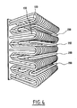
- the exchanger block consists of a first set of tubes 1 ( Figures 1 and 2) arranged parallel to each other so as to form between them intervals 100 and intervals 200 in which are housed each time a tube 50 ( Figure 3) forming the second set of recovery tubes.
- the orientation of the tubes 50 of the second set ble is such that the axis of the segments 51, 55 is perpendicular to the axis of the segments 21-29 of the tubes 1 of the first set.
- the return by the end pieces 66, 67 is made perpendicular to the direction of the segments 51-55 whereas, for the tubes 1 of the first set, the inlet / outlet ends are parallel to the segments, the two sets of tubes can be connected to a distribution and collection box for heat transfer fluid, located on the same side.
- FIGS 5-7 show such a box.
- the box is in the form of a rectangular or square ring 70 in the form of a picture frame, the sides of which bear the references 71, 72, 73, 74.
- the sides 71 and 72 are separated from the sides 73 and 74, by a partition 75-76.
- the group of sides 71-72 has an opening 77 and the sides 73-74 have a nozzle 78.
- the nozzle 77 constitutes the inlet nozzle and the nozzle 78, the outlet nozzle or vice versa.
- the cover 80 of the box 70 is shown in FIG. 7. This figure shows the connection orifices 81, 82 of the tubes 1 and the connection orifices 83, 84 of the tubes 50.
- Figure 6 shows the shape of the box with the cover 80 and the cavities corresponding to the different sides as described above.
Landscapes
- Engineering & Computer Science (AREA)
- Physics & Mathematics (AREA)
- Thermal Sciences (AREA)
- Mechanical Engineering (AREA)
- General Engineering & Computer Science (AREA)
- Heat-Exchange Devices With Radiators And Conduit Assemblies (AREA)
- Yarns And Mechanical Finishing Of Yarns Or Ropes (AREA)
- Steam Or Hot-Water Central Heating Systems (AREA)
- Air Supply (AREA)
Priority Applications (1)
| Application Number | Priority Date | Filing Date | Title |
|---|---|---|---|
| AT88402995T ATE62543T1 (de) | 1987-12-02 | 1988-11-29 | Vorrichtung zur waermerueckgewinnung. |
Applications Claiming Priority (2)
| Application Number | Priority Date | Filing Date | Title |
|---|---|---|---|
| FR8716708 | 1987-12-02 | ||
| FR8716708A FR2624268B1 (fr) | 1987-12-02 | 1987-12-02 | Echangeur de chaleur notamment un recuperateur de chaleur sur les produits de combustion tels que fumees d'un foyer d'une chaudiere ou gaz d'echappement de moteurs a combustion interne et en particulier d'une chaudiere a gaz ou d'un moteur a gaz |
Publications (2)
| Publication Number | Publication Date |
|---|---|
| EP0319392A1 true EP0319392A1 (de) | 1989-06-07 |
| EP0319392B1 EP0319392B1 (de) | 1991-04-10 |
Family
ID=9357380
Family Applications (1)
| Application Number | Title | Priority Date | Filing Date |
|---|---|---|---|
| EP88402995A Expired - Lifetime EP0319392B1 (de) | 1987-12-02 | 1988-11-29 | Vorrichtung zur Wärmerückgewinnung |
Country Status (4)
| Country | Link |
|---|---|
| EP (1) | EP0319392B1 (de) |
| AT (1) | ATE62543T1 (de) |
| DE (1) | DE3862369D1 (de) |
| FR (1) | FR2624268B1 (de) |
Cited By (1)
| Publication number | Priority date | Publication date | Assignee | Title |
|---|---|---|---|---|
| FR3053774A1 (fr) * | 2016-07-11 | 2018-01-12 | Fives Solios | Installation de refroidissement de gaz ou fumees dans un conduit de circulation a l'aide d'un dispositif de refroidissement |
Families Citing this family (2)
| Publication number | Priority date | Publication date | Assignee | Title |
|---|---|---|---|---|
| SE545085C2 (en) * | 2019-08-12 | 2023-03-28 | Enjay Ab Patent | A battery device for a ventilation system |
| KR102809333B1 (ko) * | 2019-08-12 | 2025-05-22 | 엔제이 아베 | 환기 시스템용 배터리 장치 |
Citations (7)
| Publication number | Priority date | Publication date | Assignee | Title |
|---|---|---|---|---|
| GB591602A (en) * | 1945-03-29 | 1947-08-22 | Babcock & Wilcox Ltd | Improvements in or relating to heat exchangers |
| US2529215A (en) * | 1947-11-10 | 1950-11-07 | Trane Co | Heat exchanger |
| FR2411373A1 (fr) * | 1977-12-08 | 1979-07-06 | Sirie Jean | Chaudiere a feu continu et a chauffage rapide |
| FR2465179A1 (fr) * | 1979-09-14 | 1981-03-20 | Rivalland Jean Francois | Echangeur de chaleur entre deux fluides |
| GB2100405A (en) * | 1981-05-29 | 1982-12-22 | Int Coal Refining Co | Convective heater |
| DE3345735A1 (de) * | 1983-12-17 | 1985-06-27 | Rolf 4690 Herne Oster | Waermeaustauschanlage fuer staubhaltige rauchgase |
| EP0236607A1 (de) * | 1986-03-11 | 1987-09-16 | Merrill K. Gordon | Wärmerückgewinnungsapparat und Wärmerückgewinnungsverfahren |
Family Cites Families (1)
| Publication number | Priority date | Publication date | Assignee | Title |
|---|---|---|---|---|
| DE2927096A1 (de) * | 1979-07-04 | 1981-01-15 | Hans Dipl Ing Schneider | Vorrichtung zur waermerueckgewinnung aus abgas aus zentralheizungs-kesselanlagen |
-
1987
- 1987-12-02 FR FR8716708A patent/FR2624268B1/fr not_active Expired - Fee Related
-
1988
- 1988-11-29 DE DE8888402995T patent/DE3862369D1/de not_active Expired - Fee Related
- 1988-11-29 EP EP88402995A patent/EP0319392B1/de not_active Expired - Lifetime
- 1988-11-29 AT AT88402995T patent/ATE62543T1/de not_active IP Right Cessation
Patent Citations (7)
| Publication number | Priority date | Publication date | Assignee | Title |
|---|---|---|---|---|
| GB591602A (en) * | 1945-03-29 | 1947-08-22 | Babcock & Wilcox Ltd | Improvements in or relating to heat exchangers |
| US2529215A (en) * | 1947-11-10 | 1950-11-07 | Trane Co | Heat exchanger |
| FR2411373A1 (fr) * | 1977-12-08 | 1979-07-06 | Sirie Jean | Chaudiere a feu continu et a chauffage rapide |
| FR2465179A1 (fr) * | 1979-09-14 | 1981-03-20 | Rivalland Jean Francois | Echangeur de chaleur entre deux fluides |
| GB2100405A (en) * | 1981-05-29 | 1982-12-22 | Int Coal Refining Co | Convective heater |
| DE3345735A1 (de) * | 1983-12-17 | 1985-06-27 | Rolf 4690 Herne Oster | Waermeaustauschanlage fuer staubhaltige rauchgase |
| EP0236607A1 (de) * | 1986-03-11 | 1987-09-16 | Merrill K. Gordon | Wärmerückgewinnungsapparat und Wärmerückgewinnungsverfahren |
Cited By (1)
| Publication number | Priority date | Publication date | Assignee | Title |
|---|---|---|---|---|
| FR3053774A1 (fr) * | 2016-07-11 | 2018-01-12 | Fives Solios | Installation de refroidissement de gaz ou fumees dans un conduit de circulation a l'aide d'un dispositif de refroidissement |
Also Published As
| Publication number | Publication date |
|---|---|
| ATE62543T1 (de) | 1991-04-15 |
| EP0319392B1 (de) | 1991-04-10 |
| DE3862369D1 (de) | 1991-05-16 |
| FR2624268A1 (fr) | 1989-06-09 |
| FR2624268B1 (fr) | 1990-04-20 |
Similar Documents
| Publication | Publication Date | Title |
|---|---|---|
| EP0186592B1 (de) | Plattenwärmetauscher | |
| JP2733593B2 (ja) | 蒸発器 | |
| FR2711236A1 (fr) | Echangeur de chaleur à deux rangées de tubes, en particulier pour véhicule automobile. | |
| EP0654646B1 (de) | Lamellenwärmetauscher, insbesondere Ölkühler für Kraftfahrzeug | |
| EP0964219A1 (de) | Flachrohrwärmetauscher | |
| FR2461222A2 (fr) | Conduit plat, notamment pour evaporateur | |
| US3217798A (en) | Heat exchanger | |
| FR2472732A1 (fr) | Echangeur de chaleur, en particulier condenseur a flux double ou multiple pour installations de climatisation de vehicules | |
| FR2693546A1 (fr) | Echangeur de chaleur à faisceau de tubes parallèles, en particulier pour véhicule automobile. | |
| EP0319392B1 (de) | Vorrichtung zur Wärmerückgewinnung | |
| FR2848292A1 (fr) | Plaque d'un echangeur thermique et echangeur thermique a plaques | |
| JP3594606B2 (ja) | プレート型熱交換器 | |
| JPS61193733A (ja) | 熱交換器の製造方法 | |
| EP0908691B1 (de) | Kreuzstromwärmetauscher | |
| CA2917539C (fr) | Dispositif d'echange thermique et procede de fabrication d'un tel dispositif | |
| JPH0610584B2 (ja) | 熱交換器 | |
| FR2776058A1 (fr) | Echangeur de chaleur multi-flux comportant des conduits d'entree et de sortie d'agent refrigerant interconnectes par des passages d'un tube en forme de plaque | |
| FR2629190A1 (fr) | Echangeur de chaleur pour le changement d'etat d'un fluide tel qu'evaporateur pour une installation de climatisation, en particulier pour vehicule automobile | |
| JPS6229892A (ja) | フイン付伝熱管群からなる熱交換器 | |
| FR2494421A1 (fr) | Element d'echange de chaleur | |
| JP2003302190A (ja) | コルゲートフィン型熱交換器 | |
| SU1746193A1 (ru) | Теплообменна поверхность | |
| FR2657422A1 (fr) | Echangeur de chaleur a lames, en particulier pour vehicule automobile. | |
| RU2059187C1 (ru) | Насадка градирни | |
| FR2800451A1 (fr) | Echangeur de chaleur a encombrement reduit et equipement d'un vehicule automobile comportant un tel echangeur de chaleur |
Legal Events
| Date | Code | Title | Description |
|---|---|---|---|
| PUAI | Public reference made under article 153(3) epc to a published international application that has entered the european phase |
Free format text: ORIGINAL CODE: 0009012 |
|
| AK | Designated contracting states |
Kind code of ref document: A1 Designated state(s): AT BE CH DE ES GB GR IT LI LU NL SE |
|
| 17P | Request for examination filed |
Effective date: 19890717 |
|
| 17Q | First examination report despatched |
Effective date: 19900323 |
|
| GRAA | (expected) grant |
Free format text: ORIGINAL CODE: 0009210 |
|
| AK | Designated contracting states |
Kind code of ref document: B1 Designated state(s): AT BE CH DE ES GB GR IT LI LU NL SE |
|
| PG25 | Lapsed in a contracting state [announced via postgrant information from national office to epo] |
Ref country code: IT Free format text: LAPSE BECAUSE OF FAILURE TO SUBMIT A TRANSLATION OF THE DESCRIPTION OR TO PAY THE FEE WITHIN THE PRE;WARNING: LAPSES OF ITALIAN PATENTS WITH EFFECTIVE DATE BEFORE 2007 MAY HAVE OCCURRED AT ANY TIME BEFORE 2007. THE CORRECT EFFECTIVE DATE MAY BE DIFFERENT FROM THE ONE RECORDED.SCRIBED TIME-LIMIT Effective date: 19910410 Ref country code: NL Effective date: 19910410 Ref country code: AT Effective date: 19910410 Ref country code: ES Free format text: THE PATENT HAS BEEN ANNULLED BY A DECISION OF A NATIONAL AUTHORITY Effective date: 19910410 Ref country code: SE Effective date: 19910410 Ref country code: GR Free format text: LAPSE BECAUSE OF FAILURE TO SUBMIT A TRANSLATION OF THE DESCRIPTION OR TO PAY THE FEE WITHIN THE PRESCRIBED TIME-LIMIT Effective date: 19910410 Ref country code: GB Effective date: 19910410 |
|
| REF | Corresponds to: |
Ref document number: 62543 Country of ref document: AT Date of ref document: 19910415 Kind code of ref document: T |
|
| REF | Corresponds to: |
Ref document number: 3862369 Country of ref document: DE Date of ref document: 19910516 |
|
| NLV1 | Nl: lapsed or annulled due to failure to fulfill the requirements of art. 29p and 29m of the patents act | ||
| GBV | Gb: ep patent (uk) treated as always having been void in accordance with gb section 77(7)/1977 [no translation filed] | ||
| PG25 | Lapsed in a contracting state [announced via postgrant information from national office to epo] |
Ref country code: LI Effective date: 19911130 Ref country code: LU Free format text: LAPSE BECAUSE OF NON-PAYMENT OF DUE FEES Effective date: 19911130 Ref country code: BE Effective date: 19911130 Ref country code: CH Effective date: 19911130 |
|
| PLBE | No opposition filed within time limit |
Free format text: ORIGINAL CODE: 0009261 |
|
| STAA | Information on the status of an ep patent application or granted ep patent |
Free format text: STATUS: NO OPPOSITION FILED WITHIN TIME LIMIT |
|
| 26N | No opposition filed | ||
| BERE | Be: lapsed |
Owner name: CHAUDIERES SECCACIER Effective date: 19911130 |
|
| REG | Reference to a national code |
Ref country code: CH Ref legal event code: PL |
|
| PG25 | Lapsed in a contracting state [announced via postgrant information from national office to epo] |
Ref country code: DE Effective date: 19920801 |