EP0319459A2 - Steckverbindung für Koaxialleiter, insbesondere für Antennen - Google Patents
Steckverbindung für Koaxialleiter, insbesondere für Antennen Download PDFInfo
- Publication number
- EP0319459A2 EP0319459A2 EP19880730261 EP88730261A EP0319459A2 EP 0319459 A2 EP0319459 A2 EP 0319459A2 EP 19880730261 EP19880730261 EP 19880730261 EP 88730261 A EP88730261 A EP 88730261A EP 0319459 A2 EP0319459 A2 EP 0319459A2
- Authority
- EP
- European Patent Office
- Prior art keywords
- plug
- spring
- connection according
- plug connection
- guide cylinder
- Prior art date
- Legal status (The legal status is an assumption and is not a legal conclusion. Google has not performed a legal analysis and makes no representation as to the accuracy of the status listed.)
- Granted
Links
Images
Classifications
-
- H—ELECTRICITY
- H01—ELECTRIC ELEMENTS
- H01R—ELECTRICALLY-CONDUCTIVE CONNECTIONS; STRUCTURAL ASSOCIATIONS OF A PLURALITY OF MUTUALLY-INSULATED ELECTRICAL CONNECTING ELEMENTS; COUPLING DEVICES; CURRENT COLLECTORS
- H01R9/00—Structural associations of a plurality of mutually-insulated electrical connecting elements, e.g. terminal strips or terminal blocks; Terminals or binding posts mounted upon a base or in a case; Bases therefor
- H01R9/03—Connectors arranged to contact a plurality of the conductors of a multiconductor cable, e.g. tapping connections
- H01R9/05—Connectors arranged to contact a plurality of the conductors of a multiconductor cable, e.g. tapping connections for coaxial cables
- H01R9/0518—Connection to outer conductor by crimping or by crimping ferrule
Definitions
- the invention relates to a connector for coaxial conductors, in particular for antennas according to the preamble of the main claim.
- axial plug connections are generally known. Lately, manufacturers have started to provide new, flatter angled connectors. These new plug-in connections use a socket connected to the car radio, which consists of a cylindrical insulating piece with an outer metal shell and a sleeve-like central inner conductor. The metal shell is provided with a bead.
- the associated plug according to the prior art has a central pin which is inserted into the sleeve-like inner conductor of the socket. Three spring arms will be pushed over the bead of the outer metal shell of the socket and thus form the ground connection, the spring arms engaging behind the bead also serving to mechanically fix the plug.
- this known connector does not adequately meet the requirements. Due to the vibrations in the car, the spring arms of the plug move on the metal shell of the socket, so that the electrical connection can be faulty. The same applies to the mechanical strength. In addition, the connector is not adequately shielded from interference. Furthermore, the car radio manufacturers are beginning to design the car radios in such a way that they can be easily removed from their holders or pushed back in, so that the driver has the opportunity to take the car radio with him when leaving the car. This means that the frequency of plugging is greatly increased, with a plug connection according to the prior art not being able to ensure the mechanical strength and the electrical contact after many plugging operations.
- the invention is therefore based on the object of creating a plug-in connection for coaxial conductors, in particular for antennas, in an angular shape, which ensures a reliable electrical connection and good mechanical strength even with frequent plug-in connections and strong vibrations, it also being sufficient should be protected against harmful interference.
- the plug has a guide cylinder which is designed as an overlapping resilient sleeve, which is provided over its circumference near the open end with an inward throat, and which is covered at its end opposite the open end with a shielding plate , the socket is kept elastic and reliable in operation even when the feed is not straight during the plugging process and with multiple plugging. Due to the overlapping design and the shielding plate, the plug is largely sealed against high-frequency or other harmful interference.
- a further advantageous embodiment consists in that the plug has a plurality of spring struts with locking elements Clasp is encompassed, one type of shock absorbers locking with the plug and the other type of suspension struts being lockable with the chassis of the car radio. In this way, a floating suspension of the connector is made available, whereby the production of the connection is guaranteed to be reliable even with manufacturing tolerances and multiple plug connections.
- an advantageous embodiment of the bushing is that the outer metal sheath somewhat overlaps the inner insulating piece at the end facing the bushing, i.e. something protrudes over the end face of the insulating piece, since in this way an additional electrical contact with the axial spring is made.
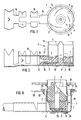
- the plug 1 of the connector consists of a guide cylinder 2, a shield plate 3 covering the guide cylinder 2 at the lower end, an axial disc-shaped spring 4, a central pin 6 provided with a connecting lug 5, which is fixed between two insulating pieces 7, 8 made of plastic .
- the guide cylinder 2 is designed as a sleeve made of metal, the ends of which are not connected to one another and overlap resiliently in accordance with the overlap region 9 according to FIG. 1.
- Tabs l0 are formed on the lower end of the guide cylinder 2, which are bent over and fix the shielding plate 3.
- this throat 11 can also be formed as a bead formed on the inner circumference of the cylinder 2.
- the axial spring 4 is designed as a disc, the circumference of which is cut at three points in the exemplary embodiment, so that there are three tabs 12 which are bent up under tension.
- the shielding plate 3 and the spring 4 have lateral guide rails 14, 15, which are guided outwards through a recess in the guide cylinder 2 perpendicular to the latter.
- 3 crimp extensions 16 are arranged laterally on the guide rail 14 of the shielding plate.
- the coaxial conductor, not shown, is pushed in the stripped state between the guide rails 14, 15 and the crimp extensions are bent vertically so that they form the lateral boundary.
- the insulating pieces 7, 8 each also have a shoulder 17, 18 arranged laterally between the guide rails 14, 15. A cavity is provided between the shoulders 17, 18 of the insulating pieces 7, 8, in which the connecting lug of the pin 6 ends.
- the stripped inner conductor of the coaxial conductor is pushed into the cavity in such a way that it forms an electrical connection with the inner conductor 5.
- the cavity is open on the side, so that the terminal lug 5 is accessible from the outside. This enables the terminal lug 5 to be soldered to the inner conductor of the coaxial cable, if desired.
- the crimp extensions 16 can also be soldered to the side guide rail 15 and the ground conductor of the coaxial cable.
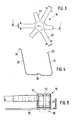
- a clip 19 For the attachment of the plug to the chassis of the car radio, a clip 19 according to FIGS. 3 and 4 is provided, which is spider-like, ie has a plurality of spring struts 21, 22 which are molded onto a central part 20.
- the struts 21 are inclined inward while the Struts 22 have an outward bias.
- Both types of struts 21, 22 are provided at their ends with bent locking lugs 23, 24.
- FIG. 5 The attachment of the plug 1 by means of the clip 19 to a chassis 25 of the car radio is shown in FIG. 5.
- the connector 1 is arranged between the inwardly bent spring struts 21 of the bracket 19 in such a way that the locking lugs 23 engage over the edge of the guide cylinder 2.
- recesses are arranged and the outwardly biased struts 22 are compressed and the detents 24 are inserted into the recesses so that they engage behind the chassis 25 under tension after releasing the struts 22.
- the socket 26 of the connector is indicated schematically, which is firmly connected to the radio itself.
- the bushing 26 has an outer metal jacket which is provided with a bead 27. After inserting the socket 26 into the plug 1, the throat 11 engages behind the bead 27.
- the length of the bead 27 is somewhat larger than the distance between the throat 11 and the bent-up tab 12 of the axial spring 4 in the rest position, so that in the inserted position State of the bush by the spring 4 an axial force acts on the bush 26. In this way, a secure electrical connection between socket 26 and connector 2 and a secure mechanical fixing is ensured.
- the socket 26 is designed in such a way that the metal shell projects slightly beyond the end face of the inner insulating piece facing the plug, as indicated in FIG. 5, so that there is also an electrical connection between the metal shell and the axial spring 4.
- FIG. 6 shows a further exemplary embodiment of the plug connection according to the invention, the plug 1 being fastened to a mounting or chassis part 25 with a clamp 28, similarly to FIG. 5.
- the connector 1 is of a simpler design in this exemplary embodiment, since the spring 4 is omitted, so that the electrical contact as an earth contact only takes place via the resilient sleeve of the guide cylinder 2.
- the central pin 6 provided with a connecting lug 5 is fixed between two insulating pieces 7, 8, which are connected with a push-button connection, and contrary to FIG. 2, in which the lower insulating piece 8 engages in the interior of the pin 6, accordingly Fig. 6, the insulating piece 8 has a recess 9, which in turn engages the pin 6.
- the bracket 28 differs from the bracket of FIGS. 3 and 4 in that it is only the Has struts 22 which have an outward bias.
- the struts 22 start from a central part 29, the central part 29 being designed as a plate in which recesses 30 are provided.
- the tabs 10 formed on the guide cylinder 2 pass through the recesses 30 below the shielding plate 3 and are then bent over.
- the recesses 30 are designed as elongated holes in such a way that the bent tabs have a certain amount of play.
- a locking ring 31 is provided which is inserted from the insertion side of the socket 26 into the opening for the plug 2 in the mounting part 25 and snap lugs 32 which engage under the mounting part 25.
- the locking ring 31 is provided with a continuous flange 33 or with projections which press on the locking elements 24 and thus fix the struts 28. In this way a floating, i.e. achieved elastic storage of the connector 1, the connection between the struts 28 and the mounting part 25 does not come off despite movement.
Landscapes
- Coupling Device And Connection With Printed Circuit (AREA)
- Details Of Connecting Devices For Male And Female Coupling (AREA)
Abstract
Description
- Die Erfindung betrifft eine Steckverbindung für Koaxialleiter, insbesondere für Antennen nach dem Oberbegriff des Hauptanspruchs.
- Für die Verwendung von Autoradios mit dem Koaxialleiter der Autoantenne sind axiale Steckverbindungen allgemein bekannt. In letzter Zeit sind die Hersteller dazu übergegangen, neue flachere Winkelsteckverbindungen vorzusehen. Bei diesen neuen Steckverbindungen wird eine mit dem Autoradio verbundene Buchse verwendet, die aus einem zylinderformigen Isolierstück mit einer äußeren Metallhülle und einem hülsenartigen mittigen Innenleiter besteht. Die Metallhülle ist dabei mit einem Wulst versehen. Der dazugehörige Stecker gemäß dem Stand der Technik weist einen mittigen Stift auf, der in den hülsenartigen Innenleiter der Buchse eingesteckt wird. Drei Federarme werden über den Wulst der äußeren Metallhülle der Buchse geschoben und bilden somit die Masseverbindung, wobei die den Wulst hintergreifenden Federarme außerdem zur mechanischen Festlegung des Steckers dienen.
- Es hat sich aber gezeigt, daß diese bekannte Steckverbindung den Anforderungen nicht ausreichend gerecht wird. Durch die Erschütterungen im Auto verschieben sich die Federarme des Steckers auf der Metallhülle der Buchse, so daß die elektrische Verbindung fehlerhaft werden kann. Entsprechendes gilt für die mechanische Festigkeit. Im übrigen ist die Steckverbindung nicht ausreichend gegen Störstrahlung abgeschirmt. Weiterhin gehen die Autoradiohersteller dazu über, die Autoradios derart zu konstruieren, daß sie leicht aus ihrer Halterung herausgenommen bzw. wieder eingeschoben werden können, damit der Fahrer die Möglichkeit hat, das Autoradio beim Verlassen des Autos mitzunehmen. Das bedeutet, daß die Steckhäufigkeit stark erhöht wird, wobei bei einer Steckverbindung gemäß dem Stand der Technik die mechanische Festigkeit und die elektrische Kontaktgabe nach vielen Steckvorgängen nicht sichergestellt sind.
- Der ,Erfindung liegt daher die Aufgabe zugrunde, eine Steckverbindung für Koaxialleiter, insbesondere für Antennen, in Winkelform zu schaffen, die auch bei häufigen Steckungen und starken Erschütterungen eine sichere elektrische Verbindung und eine gute mechanische Festigkeit gewährleistet, wobei sie außerdem ausreichend gegen schädliche Störstrahlungen gesichert sein soll.
- Diese Aufgabe wird erfindungsgemäß bei einer Steckverbindung gemäß dem Oberbegriff des Hauptanspruchs durch dessen kennzeichnende Merkmale gelöst. Dadurch, daß der Stecker einen Führungszylinder aufweist, der als überlappende federnde Manschette ausgebildet ist, die über ihrem Umfang in der Nähe des offenen Endes mit einer nach innen gerichteten Kehle versehen ist, und die an ihrem dem offenen Ende gegenüberliegenden Ende mit einem Abschirmblech abgedeckt ist, wird die Buchse elastisch und funktionssicher im Betrieb auch bei nicht gerader Zuführung beim Steckvorgang und bei Mehrfachsteckungen gehalten. Durch die überlappende Ausführung und das Abschirmblech ist der Stecker weitgehend dicht gegen hochfrequente oder sonstige schädliche Störeinstrahlungen.
- Durch die in den Unteransprüchen angegebenen Maßnahmen sind vorteilhafte Weiterbildungen und Verbesserungen möglich. Besonders vorteilhaft ist, daß in axialer Richtung eine zusätzliche Feder vorgesehen ist, die in axialer Richtung vorgespannt ist. Dadurch wird einerseits auch bei Erschütterungen ein sicherer Massekontakt aufrechterhalten und außerdem wird die mechanische Haltekraft in axialer Richtung verbessert, da eine elastische Vorspannung vorgesehen ist.
- Eine weitere vorteilhafte Ausgestaltung besteht darin, daß der Stecker von einer eine Mehrzahl von Federbeinen mit Rastelementen aufweisenden Klammer umgriffen wird, wobei die eine Art von Federbeinen mit dem Stecker verrasten und die andere Art von Federbeinen mit dem Chassis des Autoradios verrastbar sind. Auf diese Weise wird eine schwimmende Aufhängung des Steckers zur Verfügung gestellt, wodurch auch bei Fertigungstoleranzen und Mehrfachsteckungen die Herstellung der Verbindung betriebssicher gewährleistet wird.
- Eine vorteilhafte Ausgestaltung der Buchse besteht darin, daß die äußere Metallhülle das innenliegende Isolierstück an dem der Buchse zugewandten Ende etwas übergreift, d.h. etwas über die Stirnfläche des Isolierstückes herausragt, da auf diese Weise zusätzlich ein elektrischer Kontakt mit der axialen Feder hergestellt wird.
- Ein Ausführungsbeispiel der Erfindung ist in der Zeichnung dargestellt und wird in der nachfolgenden Beschreibung näher erläutert. Es zeigen:
- Fig. 1 eine Aufsicht auf ein Ausführungsbeispiel der erfindungsgemäßen Steckverbindung,
- Fig. 2 einen Schnitt durch die Steckverbindung gemäß Fig. 1,
- Fig. 3 eine Aufsicht auf ein Ausführungsbeispiel einer den Stecker festlegenden Klammer,
- Fig. 4 einen Schnitt der Klammer gemäß Fig. 3,
- Fig. 5 eine schematische Ansicht des am Chassis befestigten Steckes mit angedeuteter Buchse, und
- Fig. 6 einen Schnitt durch ein weiteres Ausführungsbeispiel der Erfindung im eingebauten Zustand.
- Der Stecker 1 der Steckverbindung besteht aus einem Führungszylinder 2, einem den Führungszylinder 2 am unteren Ende abdeckenden Abschirmblech 3, einer axialen scheibenförmigen Feder 4, einem mittigen mit einer Anschlußfahne 5 versehenen mittigen Stift 6, der zwischen zwei Isolierstücken 7, 8 aus Kunststoff festgelegt ist.
- Der Führungszylinder 2 ist als Manschette aus Metall ausgebildet, deren nicht miteinander verbundenen Enden sich gemäß dem Überlappungsbereich 9 nach Fig. 1 federnd überlappen. Am unteren Ende des Führungszylinders 2 sind Lappen l0 angeformt, die umgebogen werden und das Abschirmblech 3 festlegen. In unmittelbarer Nähe des offenen Endes des Zylinders 2 ist sein Umfang mit einer nach innen gerichteten Kehle 11 versehen. Selbstverständlich kann diese Kehle 11 auch als am inneren Umfang des Zylinders 2 angeformter Wulst ausgebildet sein.
- Die axiale Feder 4 ist als Scheibe ausgebildet, deren Umfang im Ausführungsbeispiel an drei Stellen eingeschnitten ist, so daß sich drei Lappen 12 ergeben, die unter Spannung hochgebogen sind. Auf dem Umfang des Mantels des Führungszylinders 2 sind in der Höhe der axialen Feder 4 Einschnitte angeordnet, wodurch sich Biegenasen 13 bilden, die nach innen umgebogen werden und die Feder 4 festlegen.
- Das Abschirmblech 3 und die Feder 4 weisen seitliche Führungsschienen 14, 15 auf, die durch eine Ausnehmung im Führungszylinder 2 senkrecht zu diesem nach außen geführt sind. Dabei sind seitlich an der Führungsschiene 14 des Abschirmbleches 3 Krimpansätze 16 angeordnet. Der nicht dargestellte Koaxialleiter wird im abisolierten Zustand zwischen die Führungsschienen 14, 15 geschoben und die Krimpansätze werden senkrecht hochgebogen, so daß sie die seitliche Begrenzung bilden. Auch die Isolierstücke 7, 8 weisen jeweils einen seitlichen zwischen den Führungsschienen 14, 15 angeordneten Ansatz 17, 18 auf. Zwischen den Ansätzen 17, 18 der Isolierstücke 7, 8 ist ein Hohlraum vorgesehen, in dem die Anschlußfahne des Stiftes 6 endet. Der abisolierte Innenleiter des Koaxialleiters wird derart in den Hohlraum geschoben, daß er mit dem Innenleiter 5 eine elektrische Verbindung bildet. Der Hohlraum ist seitlich offen, so daß die Anschlußfahne 5 von außen zugänglich ist. Dadurch wird ermöglicht, daß, falls gewünscht, die Anschlußfahne 5 mit dem Innenleiter des Koaxialkabels verlötet werden kann.
- Falls nötig können auch die Krimpansätze 16 mit der seitlichen Führungsschiene 15 und dem Masseleiter des Koaxialkabels verlötet werden.
- Für die Befestigung des Steckers am Chassis des Autoradios ist eine Klammer 19 gemäß Fig. 3 und 4 vorgesehen, die spinnenartig ausgebildet ist, d.h. eine Mehrzahl von Federbeinen 21, 22 aufweist, die an ein Mittelteil 20 angeformt sind. Die Federbeine 21 sind nach innen geneigt, während die Federbeine 22 eine nach außen hin gerichtete Vorspannung aufweisen. Beide Arten von Federbeinen 21, 22 sind an ihren Enden mit umgebogenen Rastnasen 23, 24 versehen.
- Die Befestigung des Steckers 1 mittels der Klammer 19 an einem Chassis 25 des Autoradios ist in Fig. 5 gezeigt. Dabei wird der Stecker 1 derart zwischen die nach innen gebogenen Federbeine 21 der Klammer 19 angeordnet, daß die Rastnasen 23 über den Rand des Führungszylinders 2 greifen. In dem Chassis 25 sind Ausnehmungen angeordnet und die nach außen vorgespannten Federbeine 22 werden zusammengedrückt und die Rastnasen 24 in die Ausnehmungen eingesteckt, so daß sie nach Loslassen der Federbeine 22 das Chassis 25 unter Spannung hintergreifen.
- In der Zeichnung nach Fig. 5 ist auch die Buchse 26 der Steckverbindung schematisch angedeutet, die mit dem Radio selbst fest verbunden ist. Die Buchse 26 weist einen äußeren Metallmantel auf, der mit einem Wulst 27 versehen ist. Nach dem Einstecken der Buchse 26 in den Stecker 1 hintergreift die Kehle 11 den Wulst 27. Dabei ist die Länge des Wulstes 27 etwas größer als der Abstand zwischen der Kehle 11 und den hochgebogenen Lappen 12 der axialen Feder 4 in Ruhestellung, so daß im eingesteckten Zustand der Buchse durch die Feder 4 eine axiale Kraft auf die Buchse 26 wirkt. Auf diese Weise wird eine sichere elektrische Verbindung zwischen Buchse 26 und Stecker 2 und eine sichere mechanische Festlegung gewährleistet. Da die Manschette des Führungszylinders 2 unter Spannung überlappend ausgebildet ist, ist ein einfaches Einstecken der Buchse 26 in den Stecker möglich, wobei nach dem Einstecken die auseinandergebogene Manschette sich wieder zusammenzieht und eine sichere elektrische Verbindung zwischen Manschette und Metallhülle der Buchse herstellt. Zusätzlich ist die Buchse 26 derart ausgestaltet, daß die Metallhülle die dem Stecker zugewandte Stirnfläche des inneren Isolierstückes, wie bei Fig. 5 angedeutet, etwas überragt, so daß auch eine elektrische Verbindung zwischen der Metallhülle und der axialen Feder 4 gegeben ist.
- In Fig. 6 ist ein weiteres Ausführungsbeispiel der erfindungsgemäßen Steckverbindung dargestellt, wobei der Stecker 1 ähnlich wie in Fig. 5 mit einer Klammer 28 an einem Montage- oder Chassisteil 25 befestigt ist. Der Stecker 1 ist in diesem Ausführungsbeispiel einfacher aufgebaut, da die Feder 4 weggelassen ist, so daß der elektrische Kontakt als Erdkontakt nur über die federnde Manschette des Führungszylinders 2 erfolgt. Entsprechend Fig. 2 wird der mit einer Anschlußfahne 5 versehene mittige Stift 6 zwischen zwei Isolierstücken 7, 8 festgelegt, die mit einer Druckknopfverbindung verbunden sind, wobei entgegen Fig. 2, bei der das untere Isolierstück 8 in das Innere des Stifts 6 eingreift, entsprechend Fig. 6 das Isolierstück 8 eine Ausnehmung 9 aufweist, in die wiederum der Anschlußstift 6 eingreift.
- Die Klammer 28 unterscheidet sich von der Klammer nach Fig. 3 und 4 darin, daß sie lediglich die Federbeine 22 aufweist, die eine nach außen hin gerichtete Vorspannung haben. Die Federbeine 22 gehen von einem Mittelteil 29 aus, wobei das Mittelteil 29 als Platte ausgebildet ist, in denen Ausnehmungen 30 vorgesehen sind. Zur Befestigung der Klammer 28 an dem Stecker 1 durchgreifen die an dem Führungszylinder 2 angeformten Lappen 10 die Ausnehmungen 30 unterhalb des Abschirmbleches 3 angeordneten Mittelteil 29 und werden anschließend umgebogen. Die Ausnehmungen 30 sind als Langlöcher derart ausgebildet, daß die umgebogenen Lappen ein gewisses Spiel haben.
- Damit die Rastnasen 24 der Federbeine 22 bei Bewegen des Steckers 1 nicht aus den Ausnehmungen im Chassis oder Montageteil 25 herausspringen, ist ein Sicherungsring 31 vorgesehen, der von der Einsteckseite der Buchse 26 in die Öffnung für den Stecker 2 im Montageteil 25 eingesteckt wird und Schnappnasen 32 aufweist, die unter das Montageteil 25 greifen. Der Sicherungsring 31 ist mit einem durchgehenden Flansch 33 oder mit Auskragungen versehen, die auf die Rastelemente 24 drücken und somit die Federbeine 28 festlegen. Auf diese Weise wird eine schwimmende, d.h. elastische Lagerung des Steckers 1 erzielt, wobei trotz Bewegung sich die Verbindung zwischen Federbeine 28 und Montageteil 25 nicht löst.
Claims (13)
Applications Claiming Priority (2)
| Application Number | Priority Date | Filing Date | Title |
|---|---|---|---|
| DE8716011U DE8716011U1 (de) | 1987-12-01 | 1987-12-01 | Steckverbindung für Koaxialleiter, insbesondere für Antennen |
| DE8716011U | 1987-12-01 |
Publications (3)
| Publication Number | Publication Date |
|---|---|
| EP0319459A2 true EP0319459A2 (de) | 1989-06-07 |
| EP0319459A3 EP0319459A3 (en) | 1990-05-30 |
| EP0319459B1 EP0319459B1 (de) | 1994-03-16 |
Family
ID=6814735
Family Applications (1)
| Application Number | Title | Priority Date | Filing Date |
|---|---|---|---|
| EP88730261A Expired - Lifetime EP0319459B1 (de) | 1987-12-01 | 1988-11-29 | Steckverbindung für Koaxialleiter, insbesondere für Antennen |
Country Status (2)
| Country | Link |
|---|---|
| EP (1) | EP0319459B1 (de) |
| DE (2) | DE8716011U1 (de) |
Cited By (3)
| Publication number | Priority date | Publication date | Assignee | Title |
|---|---|---|---|---|
| EP0555949A1 (de) * | 1992-02-14 | 1993-08-18 | Robert Karst GmbH & Co. KG. | Befestigungsvorrichtung für eine Steckverbindung für Geräte des mobilen Einsatzes |
| EP1005106A3 (de) * | 1998-11-27 | 2001-07-11 | Sumitomo Wiring Systems, Ltd. | Anschluss und Anpressverfahren |
| CN100373708C (zh) * | 2002-12-26 | 2008-03-05 | 广濑电机株式会社 | 同轴电连接器 |
Family Cites Families (2)
| Publication number | Priority date | Publication date | Assignee | Title |
|---|---|---|---|---|
| DE3604896A1 (de) * | 1986-02-15 | 1987-08-20 | Bosch Gmbh Robert | Koaxialer winkelstecker |
| DE8617227U1 (de) * | 1986-06-27 | 1986-08-14 | Robert Bosch Gmbh, 7000 Stuttgart | Verlängerungskabel für ein mit einer Fahrzeugantenne verbundenes Antennenkabel |
-
1987
- 1987-12-01 DE DE8716011U patent/DE8716011U1/de not_active Expired
-
1988
- 1988-11-29 EP EP88730261A patent/EP0319459B1/de not_active Expired - Lifetime
- 1988-11-29 DE DE88730261T patent/DE3888470D1/de not_active Expired - Fee Related
Cited By (3)
| Publication number | Priority date | Publication date | Assignee | Title |
|---|---|---|---|---|
| EP0555949A1 (de) * | 1992-02-14 | 1993-08-18 | Robert Karst GmbH & Co. KG. | Befestigungsvorrichtung für eine Steckverbindung für Geräte des mobilen Einsatzes |
| EP1005106A3 (de) * | 1998-11-27 | 2001-07-11 | Sumitomo Wiring Systems, Ltd. | Anschluss und Anpressverfahren |
| CN100373708C (zh) * | 2002-12-26 | 2008-03-05 | 广濑电机株式会社 | 同轴电连接器 |
Also Published As
| Publication number | Publication date |
|---|---|
| DE8716011U1 (de) | 1988-01-21 |
| DE3888470D1 (de) | 1994-04-21 |
| EP0319459A3 (en) | 1990-05-30 |
| EP0319459B1 (de) | 1994-03-16 |
Similar Documents
| Publication | Publication Date | Title |
|---|---|---|
| DE19500959C2 (de) | Elektrischer Steckverbinder | |
| DE69207279T3 (de) | Koaxialverbinder zum Verbinden eines Koaxialkabels mit einer elektronischen gedruckten Schaltung | |
| DE102017113875B3 (de) | Elektrischer Stecker mit einem Schutzleiterkontakt und damit einstückig ausgebildeten Schutzleiterverbindungselement zur Erdung von Außenteilen | |
| EP0772261A2 (de) | Koaxial-Steckverbindung | |
| DE1615001B2 (de) | Elektrische steckvorrichtung | |
| EP0848459A2 (de) | Leitungs-Steckverbindung | |
| EP3613110B1 (de) | Baugruppe für ein steckverbinderteil mit einem kontakteinsatz und einem erdungselement | |
| WO2007141249A1 (de) | Bürstensystem mit entstörplatine | |
| EP2380241A1 (de) | Kontaktierungsstecker sowie kontaktierungssteckverbindung | |
| EP3605746B1 (de) | Steckverbinder sowie steckverbindung mit einem solchen steckverbinder | |
| DE4310369A1 (de) | Adapter | |
| DE7824507U1 (de) | Elektromagnetisches Relais | |
| EP0319459B1 (de) | Steckverbindung für Koaxialleiter, insbesondere für Antennen | |
| DE102006004782A1 (de) | Verrastungsvorrichtung für einen elektrischen Kontakt sowie Verfahren zur Herstellung einer Verrastungsvorrichtung | |
| EP1467431B1 (de) | Kontaktadapter für die Kontaktierung einer Antennenstruktur eines Fahrzeuges | |
| DE102016006923B4 (de) | Koaxialsteckverbinder | |
| DE102004004203B4 (de) | Verbindungsanordnung mit einem Verbindungselement und einem Lampensockel | |
| DE29521491U1 (de) | Elektrischer Steckverbinder | |
| DE19525801C2 (de) | Vorrichtung zum elektrisch leitenden Verbinden von zwei elektrischen Leitungen | |
| EP3830910B1 (de) | Steckvorrichtung mit verrastbaren komponenten | |
| EP1149436A1 (de) | Hf-koaxial-winkel-steckverbinderteil | |
| DE102008054950A1 (de) | Kontaktierungsvorrichtung | |
| DE2547951A1 (de) | Steckerbuchse | |
| EP1811613A1 (de) | Kuppler, insbesondere Winkelkuppler nach dem Fakra-Standard, für fahrzeugtechnische Anwendungen | |
| EP1734620B1 (de) | Mittelkontakt für eine Glühlampenfassung |
Legal Events
| Date | Code | Title | Description |
|---|---|---|---|
| PUAI | Public reference made under article 153(3) epc to a published international application that has entered the european phase |
Free format text: ORIGINAL CODE: 0009012 |
|
| AK | Designated contracting states |
Kind code of ref document: A2 Designated state(s): DE ES FR GB IT NL |
|
| PUAL | Search report despatched |
Free format text: ORIGINAL CODE: 0009013 |
|
| AK | Designated contracting states |
Kind code of ref document: A3 Designated state(s): DE ES FR GB IT NL |
|
| 17P | Request for examination filed |
Effective date: 19901128 |
|
| 17Q | First examination report despatched |
Effective date: 19920228 |
|
| RAP3 | Party data changed (applicant data changed or rights of an application transferred) |
Owner name: ROBERT KARST GMBH & CO. KG. |
|
| GRAA | (expected) grant |
Free format text: ORIGINAL CODE: 0009210 |
|
| AK | Designated contracting states |
Kind code of ref document: B1 Designated state(s): DE ES FR GB IT NL |
|
| PG25 | Lapsed in a contracting state [announced via postgrant information from national office to epo] |
Ref country code: NL Effective date: 19940316 Ref country code: GB Effective date: 19940316 Ref country code: FR Effective date: 19940316 Ref country code: ES Free format text: THE PATENT HAS BEEN ANNULLED BY A DECISION OF A NATIONAL AUTHORITY Effective date: 19940316 |
|
| REF | Corresponds to: |
Ref document number: 3888470 Country of ref document: DE Date of ref document: 19940421 |
|
| ITF | It: translation for a ep patent filed | ||
| EN | Fr: translation not filed | ||
| NLV1 | Nl: lapsed or annulled due to failure to fulfill the requirements of art. 29p and 29m of the patents act | ||
| GBV | Gb: ep patent (uk) treated as always having been void in accordance with gb section 77(7)/1977 [no translation filed] |
Effective date: 19940316 |
|
| PLBE | No opposition filed within time limit |
Free format text: ORIGINAL CODE: 0009261 |
|
| STAA | Information on the status of an ep patent application or granted ep patent |
Free format text: STATUS: NO OPPOSITION FILED WITHIN TIME LIMIT |
|
| 26N | No opposition filed | ||
| PGFP | Annual fee paid to national office [announced via postgrant information from national office to epo] |
Ref country code: IT Payment date: 20061130 Year of fee payment: 19 Ref country code: DE Payment date: 20061130 Year of fee payment: 19 |
|
| PG25 | Lapsed in a contracting state [announced via postgrant information from national office to epo] |
Ref country code: DE Free format text: LAPSE BECAUSE OF NON-PAYMENT OF DUE FEES Effective date: 20080603 |
|
| PG25 | Lapsed in a contracting state [announced via postgrant information from national office to epo] |
Ref country code: IT Free format text: LAPSE BECAUSE OF NON-PAYMENT OF DUE FEES Effective date: 20071129 |