EP0319476A2 - Device for sorting and piling valuable papers, particularly bank notes - Google Patents
Device for sorting and piling valuable papers, particularly bank notes Download PDFInfo
- Publication number
- EP0319476A2 EP0319476A2 EP88810805A EP88810805A EP0319476A2 EP 0319476 A2 EP0319476 A2 EP 0319476A2 EP 88810805 A EP88810805 A EP 88810805A EP 88810805 A EP88810805 A EP 88810805A EP 0319476 A2 EP0319476 A2 EP 0319476A2
- Authority
- EP
- European Patent Office
- Prior art keywords
- notes
- sorting
- transport
- transport route
- deflector
- Prior art date
- Legal status (The legal status is an assumption and is not a legal conclusion. Google has not performed a legal analysis and makes no representation as to the accuracy of the status listed.)
- Withdrawn
Links
Images
Classifications
-
- B—PERFORMING OPERATIONS; TRANSPORTING
- B65—CONVEYING; PACKING; STORING; HANDLING THIN OR FILAMENTARY MATERIAL
- B65H—HANDLING THIN OR FILAMENTARY MATERIAL, e.g. SHEETS, WEBS, CABLES
- B65H31/00—Pile receivers
- B65H31/04—Pile receivers with movable end support arranged to recede as pile accumulates
- B65H31/06—Pile receivers with movable end support arranged to recede as pile accumulates the articles being piled on edge
-
- B—PERFORMING OPERATIONS; TRANSPORTING
- B65—CONVEYING; PACKING; STORING; HANDLING THIN OR FILAMENTARY MATERIAL
- B65H—HANDLING THIN OR FILAMENTARY MATERIAL, e.g. SHEETS, WEBS, CABLES
- B65H29/00—Delivering or advancing articles from machines; Advancing articles to or into piles
- B65H29/38—Delivering or advancing articles from machines; Advancing articles to or into piles by movable piling or advancing arms, frames, plates, or like members with which the articles are maintained in face contact
- B65H29/40—Members rotated about an axis perpendicular to direction of article movement, e.g. star-wheels formed by S-shaped members
-
- B—PERFORMING OPERATIONS; TRANSPORTING
- B65—CONVEYING; PACKING; STORING; HANDLING THIN OR FILAMENTARY MATERIAL
- B65H—HANDLING THIN OR FILAMENTARY MATERIAL, e.g. SHEETS, WEBS, CABLES
- B65H29/00—Delivering or advancing articles from machines; Advancing articles to or into piles
- B65H29/58—Article switches or diverters
- B65H29/60—Article switches or diverters diverting the stream into alternative paths
-
- G—PHYSICS
- G07—CHECKING-DEVICES
- G07D—HANDLING OF COINS OR VALUABLE PAPERS, e.g. TESTING, SORTING BY DENOMINATIONS, COUNTING, DISPENSING, CHANGING OR DEPOSITING
- G07D11/00—Devices accepting coins; Devices accepting, dispensing, sorting or counting valuable papers
- G07D11/50—Sorting or counting valuable papers
-
- B—PERFORMING OPERATIONS; TRANSPORTING
- B65—CONVEYING; PACKING; STORING; HANDLING THIN OR FILAMENTARY MATERIAL
- B65H—HANDLING THIN OR FILAMENTARY MATERIAL, e.g. SHEETS, WEBS, CABLES
- B65H2301/00—Handling processes for sheets or webs
- B65H2301/40—Type of handling process
- B65H2301/42—Piling, depiling, handling piles
- B65H2301/421—Forming a pile
- B65H2301/4214—Forming a pile of articles on edge
- B65H2301/42146—Forming a pile of articles on edge by introducing articles from above
-
- B—PERFORMING OPERATIONS; TRANSPORTING
- B65—CONVEYING; PACKING; STORING; HANDLING THIN OR FILAMENTARY MATERIAL
- B65H—HANDLING THIN OR FILAMENTARY MATERIAL, e.g. SHEETS, WEBS, CABLES
- B65H2404/00—Parts for transporting or guiding the handled material
- B65H2404/20—Belts
- B65H2404/26—Particular arrangement of belt, or belts
- B65H2404/261—Arrangement of belts, or belt(s) / roller(s) facing each other for forming a transport nip
- B65H2404/2611—Arrangement of belts, or belt(s) / roller(s) facing each other for forming a transport nip forming curved transport path
-
- B—PERFORMING OPERATIONS; TRANSPORTING
- B65—CONVEYING; PACKING; STORING; HANDLING THIN OR FILAMENTARY MATERIAL
- B65H—HANDLING THIN OR FILAMENTARY MATERIAL, e.g. SHEETS, WEBS, CABLES
- B65H2701/00—Handled material; Storage means
- B65H2701/10—Handled articles or webs
- B65H2701/19—Specific article or web
- B65H2701/1912—Banknotes, bills and cheques or the like
Definitions
- the invention relates to a sorting and stacking device for notes of value, in particular bank notes, for separating and stacking notes of value provided with a marking according to the preamble of claim 1.
- Sorting and stacking devices of the type described above are known, for example, from DE-A-2 711 084 and from DD-A-154 070.
- the device for separating out the marked notes of value consists of a rotating suction roller installed behind the detector, the peripheral speed of which is synchronized with the conveying speed of the notes of value, which on the first, straight-line transport route through a transport chain be moved with bumpers.
- the circumference of the suction roller has suction openings, which are temporarily connected to a vacuum source with the help of a solenoid valve controlled by the detector, so that the suction roller lifts an incoming misprint from the transport chain by suction, takes it along and feeds it to the magazine in which the mispressures are stacked.
- the perfect banknotes are moved on the transport chain without being caught by the suction roller, for example to a numbering device.
- Another sorting device working with cooperating transport drums is known from DD-A-61883, in which marked, to be separated out notes pass from the circumference of a first transport drum to the circumference of a second transport drum, which functions as a sorting drum, while perfect notes are taken over by a third transport drum and for further processing.
- the invention has for its object to provide a sorting and stacking device according to the preamble of claim 1 which, while avoiding suction rolls, can be operated at higher conveying speeds than previous devices, works reliably and trouble-free and allows better use of the available space.
- the deflector preferably in the form of a light deflection plate, is in its idle state below the level of the first transport path and can be tilted very quickly into its deflection position if the detector reports an incorrect pressure, because only a small tilt angle is required for this.
- the second transport section consists of a pair of transport belts lying one on top of the other along this section, between which a deflected misprint is pushed, and since the end of this section runs essentially tangentially to a curved slot of the storage wheel, the separated notes of value are securely inserted into the slots of the storage wheel transported, the desired high conveying speeds can be achieved without further notice.
- the storage of the separated banknotes in a horizontally extending magazine, in which they are stacked upright, in a vertical position, next to one another, is particularly favorable; namely, this magazine can be made quite long, so that longer stacks of notes of value can be obtained than is generally possible with vertical stacks, since the height of vertical magazines is often limited for reasons of space and therefore these magazines are ent need to be emptied or replaced frequently.
- the overall height of the device according to the invention is essentially determined only by the diameter of the storage wheel and can therefore be dimensioned much smaller than in previously known devices.
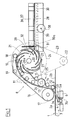
- the device has a first transport path 1 for cut-to-size bank notes 2a, 2b, which are moved from left to left in the illustration according to FIG. 1 by a known chain conveyor C with push fingers, not shown, as described, for example, in DD-A-154070 be transported on the right.
- a separating device 3 is arranged, which has a deflector 3a in the form of a deflection plate, which is pivotally mounted at one of its ends on a horizontal axis 4 lying transversely to the conveying direction.
- This baffle plate is provided with an extension 3b which is oriented approximately perpendicular to its plane and is kinematically connected to a bistable electromagnetic device 6 which allows the deflector 3a to be pivoted between a rest position 5a and a deflection position 5b.
- the deflector 3a In the rest position 5a shown in broken lines, the deflector 3a is located completely below the level of the transport route 1, while in the inclined deflection position 5b it crosses the level of the transport route 1 and tangentially directs a value note 2a coming from the left towards a second transport route, which later is described.
- the bistable electromagnetic device 6, which can also be another equivalent device, is controlled by a detector, not shown, which is installed on the transport path 1 in the conveying direction in front of the separating device 3.
- This detector responds when a note 2a, for example marked with a fluorescent color or another known material, is moved past it, and emits a signal so that the deflector 3a deflects the marked note 2a to the second transport route. As soon as the note has reached the second transport route, the deflector 3a returns to its rest position 5a.
- a first belt arrangement 7 and a second belt arrangement 8 are provided, which have a pair of interacting endless belts 12, 16.
- the first belt arrangement 7 includes the endless belt 12, two end rollers 9 and 10 and a plurality of rollers 11 arranged between them, which guide the belt 12, and a roller 13 which drives this belt 12 by friction.
- rollers 14 and 15 deflecting the belt 12 and pressing against this roller 13 are provided on both sides of the roller 13.
- the second belt arrangement 8 has an endless belt 16 which is guided by two end rollers 17 and 18 and an intermediate roller 19 which keep the lower and the upper run of the belt 16 at a distance; Without this roller 19, the upper and lower run of the belt 16 would touch due to the course of the belts.
- the relative position of the belt arrangements 7 and 8 is selected such that the two endless belts 12 and 16 lie on one another in contact with one another along a path forming the second transport path.
- This second transport route begins between the end rollers 9 and 17 above the separating device 3, in the extension of the deflector 3a taking up its deflection position, runs along a curved path upwards and ends between the end rollers 10 and 18.
- a storage wheel which consists of a plurality of disks 20 which are arranged at an axial distance from one another and which rotate on one horizontal shaft 20a sit.
- Each disk 20 has spiral slits 21 which extend from the inner disk area to the disk circumference and open there approximately tangentially to this circumference.
- the slots located in the same angular ranges of the adjacent disks 20 form receiving openings for the notes of value leaving the second transport path.
- the end of this transport route that is to say the end of the curved path traversed by the notes of value, is oriented at least approximately tangentially to the circumference of the disks 20 and thus to the mouth of the slots 21, which are in their extension when passing the end of the second transport route.
- a drive pulley 22 which drives a pulley 24, which is non-rotatably seated on the shaft 20a, by means of a belt 23.
- the endless belt 12 is driven by a further belt 25, which has a pulley 27, which is also non-rotatably seated on the shaft 20a, and a pulley which is non-rotatably seated on the axis of the roller 13 26 runs.
- the endless belt 16 is driven in such a way that it is entrained by the endless belt 12 due to friction.
- a separate drive for the endless belt 16 can also be provided.
- the ratio of the diameters of the pulleys 24, 26 and 27 is chosen so that the peripheral speed of the pulleys 20 is the speed of the endless belts 12 and 16 and consequently the conveying speed of the belts tated notes of value is adapted such that each note of value arriving at the end of the second transport route reaches one of the slots 21 of the storage wheel.
- the conveying speed of the notes of value along the second transport route is equal to or at least compatible with the conveying speed of the notes of value on the first transport route 1.
- ribbed belts and toothed rollers or pulleys are preferably used.
- the ratio of the diameters of the pulleys 22 and 24 to 1: 4.5 and the ratio of the diameters of the pulleys 27 and 26 to 7.2: 1 are selected.
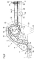
- a magazine On the circumference of the storage wheel, approximately offset by an angle of 90 ° with respect to the end of the second transport section with the belt arrangements 7, 8, a magazine is arranged which essentially has a horizontal base plate 28 and a plate-shaped stop 29 oriented perpendicularly to this .
- This stop 29 is mounted by means of a sleeve 31 on a shaft 30 installed under the base plate 28 and is displaceable thereon.
- the sleeve 31 is subject to the action of a pressing member 30a, in the example considered a spring which presses the stop 29 in the direction of the end of the base plate 28 adjacent to the storage wheel (FIGS. 1 and 2).
- An inclined plate 32 fastened at the beginning of the magazine is provided with projections which engage between the disks 20 and form deflection members 32a (FIG. 4) crossing the slots 21.
- the notes of value located in the slots 21 of the disks 20 After they have undergone a rotation of approximately 90 ° with the storage wheel, their edge abuts against the deflection members 32a, is stopped there and then approximately upright during the rotation of the storage wheel from the rear slot edges in the direction of rotation and the adjacent peripheral sections of the disks 20 Position out of the slots 21 and pressed against the stop 29 of the magazine, which is pushed against the action of the spring under the thrust of the successively arriving notes. In this way, the separated notes of value on the base plate 28, standing upright, form a horizontal stack (FIG. 2).
- the magazine In order to hold and guide the stacked notes of value 2a laterally, the magazine has two side plates 36 and 37 which are oriented perpendicular to the base plate 28 and are arranged parallel and at a distance from one another. So that their distance can be adjusted to the width of the notes of value, a screw 39 is provided which is connected to a wheel 38 and which engages in two screw nuts (not shown) which are each fastened to one of the two side plates 36 and 37. By turning the wheel 38, the side plates are shifted in opposite directions to adjust them to the width of the notes of value.
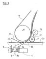
- a curved guide plate 34 (FIG. 3) is provided at the level of the two end rollers 9 and 17, which are in the extension of the deflector 3a lies when it takes up its deflection position 5a, so that the front end raised by the deflector 3a Werteins 2a is guided between the two endless belts 12 and 16; the point at which the two endless belts 12 and 16 begin to touch between the rollers 9 and 17 cannot be moved very close to the branching point of the rejection device.
- a curved plate or another similar element is provided as a guide element 35 which pushes this note against the plane the first transport route 1 presses. This prevents the relevant note from losing contact with the chain conveyor due to the stiffness of the paper when its front end is raised by the deflector 3a.
- the perfect banknotes 2b are moved further on the chain conveyor C.
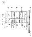
- FIG. 4 shows a preferred embodiment of the device according to the invention, in which instead of a pair of endless belts 12, 16, three pairs of endless belts 12 ', 16'; 12 ⁇ , 16 ⁇ and 12 ′′′, 16 ′′′ and a storage wheel consisting of four disks 20 are provided.
- the belts are driven and guided by a corresponding number of rollers in a manner similar to that described with reference to FIG. 1.
- 4 shows schematically the shaft 20a mounted in a frame B with the four disks 20 of the storage wheel and the pulleys 24, 27, the end rollers 18 ', 18 ⁇ and 18 ′′′, which sit on a shaft 33 also mounted in the frame B.
- the invention is not limited to the exemplary embodiment described, but rather permits multiple variants with regard to the design of all parts and their drive.
Landscapes
- Engineering & Computer Science (AREA)
- Mechanical Engineering (AREA)
- Physics & Mathematics (AREA)
- General Physics & Mathematics (AREA)
- Pile Receivers (AREA)
- Delivering By Means Of Belts And Rollers (AREA)
- Separation, Sorting, Adjustment, Or Bending Of Sheets To Be Conveyed (AREA)
- Discharge By Other Means (AREA)
Abstract
Die Vorrichtung dient zum Aussondern von mit einer Markierung versehenen Wertscheinen (2a), die zu einer Folge von kontinuierlich hintereinander auf einer ersten Transportstrecke (1) in Form eines Kettenförderers (C) fortbewegten Wertscheinen gehören, und weist einen auf die Markierungen ansprechenden Detektor und eine von diesem gesteuerte Aussonderungseinrichtung (3) auf, welche die markierten Wertscheine (2a) über eine zweite Transportstrecke (7, 8) einem Magazin (28 bis 31) zuführt. Die zweite Transportstrecke hat wenigstens ein Paar von angetriebenen endlosen Riemen (12, 16), die längs dieser Strecke unter Berührung aufeinanderliegen. Die Aussonderungseinrichtung (3) arbeitet mit einem Ablenker (3a), der einen markierten Wertschein vom Kettenförderer (C) abhebt und zwischen diese Riemen lenkt. Hinter der zweiten Transportstrecke ist ein rotierendes Speicherrad mit die Wertscheine aufnehmenden spiralförmigen Schlitzen (21) angeordnet, aus denen die Wertscheine mittels Ablenkgliedern hochkant in das horizontale Magazin gegen einen verschiebbaren federbelasteten Anschlag (29) geschoben werden. 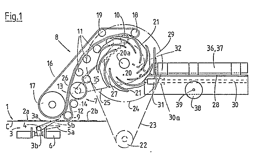
Description
Die Erfindung bezieht sich auf eine Sortier- und Stapelvorrichtung für Wertscheine, insbesondere Banknoten, zum Aussondern und Stapeln von mit einer Markierung versehenen Wertscheinen gemäss dem Oberbegriff des Anspruchs 1.The invention relates to a sorting and stacking device for notes of value, in particular bank notes, for separating and stacking notes of value provided with a marking according to the preamble of claim 1.
Beim Druck von Wertscheinen, insbesondere Banknoten, Aktien oder anderen Dokumenten, werden im allgemeinen grosse Bögen bedruckt, die eine Vielzahl individueller Aufdrucke haben. Diese Bögen werden visuell oder automatisch auf Druckfehler kontrolliert, wobei auszusondernde Fehldrucke mit einer Markierung versehen werden, beispielsweise mit einer fluoreszierenden Farbe. Die Bögen werden dann in Einzelnutzen geschnitten, und diese Einzelnutzen werden an einem Detektor vorbeigeführt, welcher die Markierungen liest. Anschliessend passieren die Einzelnutzen eine von diesem Detektor gesteuerte Sortiervorrichtung, welche die markierten Fehldrucke automatisch aussondert, während die einwandfreien Einzelnutzen einer weiteren Verarbeitung zugeführt werden, beispielsweise dem Aufdruck einer Nummer.When printing banknotes, in particular banknotes, shares or other documents, large sheets are printed which have a large number of individual prints. These sheets are checked visually or automatically for printing errors, misprints to be discarded being provided with a marking, for example with a fluorescent color. The sheets are then cut into single sheets and these single sheets are guided past a detector which reads the markings. The individual blanks then pass through a sorting device controlled by this detector, which automatically separates the marked misprints, while the flawless individual blanks are fed to further processing, for example the printing of a number.
Sortier- und Stapelvorrichtungen der vorstehend beschriebenen Art sind beispielsweise aus der DE-A-2 711 084 und aus der DD-A-154 070 bekannt. Hierbei besteht die Einrichtung zum Aussondern der markierten Wertscheine aus einer hinter dem Detektor installierten rotierenden Ansaugwalze, deren Umfangsgeschwindigkeit mit der Fördergeschwindigkeit der Wertscheine synchronisiert ist, welche auf der ersten, gradlinig verlaufenden Transportstrecke durch eine Transportkette mit Stossfingern bewegt werden. Die Ansaugwalze weist an ihrem Umfang Saugöffnungen auf, die mit Hilfe eines vom Detektor gesteuerten Magnetventils zeitweise an eine Unterdruckquelle angeschlossen werden, damit die Ansaugwalze einen ankommenden Fehldruck durch Ansaugung von der Transportkette abhebt, mitnimmt und dem Magazin zuführt, in welchem die Fehldrucke gestapelt werden. Die einwandfreien Wertscheine werden dagegen, ohne von der Ansaugwalze erfasst zu werden, auf der Transportkette weiterbewegt, beispielsweise zu einer Numeriervorrichtung.Sorting and stacking devices of the type described above are known, for example, from DE-A-2 711 084 and from DD-A-154 070. In this case, the device for separating out the marked notes of value consists of a rotating suction roller installed behind the detector, the peripheral speed of which is synchronized with the conveying speed of the notes of value, which on the first, straight-line transport route through a transport chain be moved with bumpers. The circumference of the suction roller has suction openings, which are temporarily connected to a vacuum source with the help of a solenoid valve controlled by the detector, so that the suction roller lifts an incoming misprint from the transport chain by suction, takes it along and feeds it to the magazine in which the mispressures are stacked. On the other hand, the perfect banknotes are moved on the transport chain without being caught by the suction roller, for example to a numbering device.
Es hat sich jedoch gezeigt, dass diese bekannten Sortier- und Stapelvorrichtungen hinsichtlich der erzielbaren Fördergeschwindigkeit der Wertscheine nicht den gewünschten Anforderungen entsprechen. Im Rahmen der modernen Wertscheinverarbeitung, insbesondere Banknotenverarbeitung, sollte die Fördergeschwindigkeit wenigstens 30.000 Wertscheine je Stunde betragen. Auf Grund der Trägheit der bekannten Systeme, insbesondere der Steuerung der die Ansaugwalze an die Unterdruckquelle anschliessenden Magnetventile, und auf Grund der Zeitspanne, die zur Erzeugung eines hinreichend starken Unterdrucks an den Saugöffnungen erforderlich ist, ist der Betrieb dieser Vorrichtungen bei höheren Förder-und Verarbeitungsgeschwindigkeiten störanfällig, und die wünschenswerten hohen Geschwindigkeiten lassen sich praktisch nicht erreichen. Da ausserdem die Ansaugwalze mit einer Andruckwalze zusammenarbeiten muss, erfordern diese bekannten Vorrichtungen ungünstigerweise einen ziemlich grossen Raumbedarf in vertikaler Richtung.However, it has been shown that these known sorting and stacking devices do not meet the desired requirements with regard to the achievable conveying speed of the notes of value. In the context of modern banknote processing, in particular banknote processing, the conveying speed should be at least 30,000 banknotes per hour. Due to the inertia of the known systems, in particular the control of the solenoid valves connecting the suction roller to the vacuum source, and due to the time required to generate a sufficiently strong vacuum at the suction openings, these devices can be operated at higher conveying and processing speeds susceptible to interference and the desirable high speeds are practically impossible to achieve. In addition, since the suction roll has to cooperate with a pressure roll, these known devices disadvantageously require a fairly large space requirement in the vertical direction.
Aehnliche Nachteile weist eine andere bekannte, in der GB-A-2 006 168 beschriebene Sortier- und Stapelvorrichtung für Wertscheine auf, welche mehrere zusammen wirkenden Ansaugwalzen und ausserdem ein mit der letzten Ansaugwalze zusammenwirkendes Speicherrad aufweist, das mehrere, im Abstand voneinander liegende Scheiben mit spiralförmigen Schlitzen zur Aufnahme der auszusondernden Wertscheine hat. Die Aussonderungseinrichtung besteht hierbei aus elektromagnetisch betätigbaren Ablenkklingen, welche in der Ablenkstellung tangential an der letzten Ansaugwalze anliegen und den auszusondernden Wertschein vom Umfang dieser Ansaugwalze abheben. Bei Gegenwart nicht auszusondernder Wertscheine dagegen sind die Ablenkklingen vom Umfang der Ansaugwalze abgehoben, so dass die Wertscheine auf dieser weiterbewegt und vom Speicherrad, das oberhalb dieser Ansaugwalze montiert ist, übernommen werden. Aus den Schlitzen des Speicherrades werden die Wertscheine mit Hilfe einer stationären Ablenkplatte in ein Magazin geschoben, wo sie, hochkant auf einer Grundplatte aufliegend, gegen einen verschiebbaren, federbelasteten Anschlag gedrückt werden.Similar disadvantages have another known sorting and stacking device for banknotes, which is described in GB-A-2 006 168 and which combines several acting suction rollers and also has a cooperating with the last suction roller storage wheel, which has several spaced disks with spiral slots for receiving the notes to be separated. The separating device here consists of electromagnetically actuated deflecting blades which lie tangentially on the last suction roller in the deflecting position and lift the value note to be separated from the scope of this suction roller. In the presence of notes of value that are not to be separated out, however, the deflecting blades are lifted from the circumference of the suction roller, so that the notes of value are moved further on and are taken over by the storage wheel which is mounted above this suction roller. With the help of a stationary deflection plate, the banknotes are pushed out of the slots of the storage wheel into a magazine, where they are pressed against a sliding, spring-loaded stop, lying on edge on a base plate.
Eine andere, mit zusammenwirkenden Transporttrommeln arbeitende Sortiervorrichtung ist aus der DD-A-61883 bekannt, bei welcher markierte, auszusondernde Wertscheine vom Umfang einer ersten Transporttrommel auf den Umfang einer zweiten, als Aussonderungstrommel fungierenden Transporttrommel gelangen, während einwandfreie Wertscheine von einer dritten Transporttrommel übernommen und der Weiterverarbeitung zugeführt werden.Another sorting device working with cooperating transport drums is known from DD-A-61883, in which marked, to be separated out notes pass from the circumference of a first transport drum to the circumference of a second transport drum, which functions as a sorting drum, while perfect notes are taken over by a third transport drum and for further processing.
Der Erfindung liegt die Aufgabe zugrunde, eine Sortier- und Stapelvorrichtung gemäss dem Oberbegriff des Anspruchs 1 zu schaffen, die, unter Vermeidung von Saugwalzen, mit höheren Fördergeschwindigkeiten als bisherige Vorrichtungen betrieben werden kann, zuverlässig und störungsfrei arbeitet und eine bessere Ausnutzung des zur Verfügung stehenden Raumes erlaubt.The invention has for its object to provide a sorting and stacking device according to the preamble of claim 1 which, while avoiding suction rolls, can be operated at higher conveying speeds than previous devices, works reliably and trouble-free and allows better use of the available space.
Diese Aufgabe wird erfindungsgemäss durch die im kennzeichnenden Teil des Anspruchs 1 angegebenen Merkmale gelöst.This object is achieved according to the invention by the features specified in the characterizing part of claim 1.
Die Vorteile der Vorrichtung nach der Erfindung sind die folgenden :The advantages of the device according to the invention are the following:
Der Ablenker, vorzugsweise in Form einer leichten Ablenkplatte, befindet sich in seinem Ruhezustand unterhalb der Ebene der ersten Transportstrecke und kann, wenn der Detektor einen Fehldruck meldet, sehr rasch in seine Ablenkstellung gekippt werden, weil dazu nur ein kleiner Kippwinkel erforderlich ist. Da die zweite Transportstrecke aus einem Paar von längs dieser Strecke aufeinanderliegenden Transportriemen besteht, zwischen die ein abgelenkter Fehldruck geschoben wird, und da das Ende dieser Strecke im wesentlichen tangential zu einem gekrümmten Schlitz des Speicherrades verläuft, werden die ausgesonderten Wertscheine sicher in die Schlitze des Speicherrades transportiert, wobei ohne weiteres die gewünschten hohen Fördergeschwindigkeiten erzielbar sind.The deflector, preferably in the form of a light deflection plate, is in its idle state below the level of the first transport path and can be tilted very quickly into its deflection position if the detector reports an incorrect pressure, because only a small tilt angle is required for this. Since the second transport section consists of a pair of transport belts lying one on top of the other along this section, between which a deflected misprint is pushed, and since the end of this section runs essentially tangentially to a curved slot of the storage wheel, the separated notes of value are securely inserted into the slots of the storage wheel transported, the desired high conveying speeds can be achieved without further notice.
Die Ablage der ausgesonderten Wertscheine in einem sich horizontal erstreckenden Magazin, in welchem sie hochkant, in vertikaler Position, nebeneinander gestapelt werden, ist besonders günstig; dieses Magazin kann nämlich ziemlich lang ausgebildet werden, so dass längere Wertscheinstapel erhalten werden können als es im allgemeinen bei vertikalen Stapeln möglich ist, da die Höhe von vertikalen Magazinen aus Raumgründen häufig begrenzt ist und daher diese Magazine ent sprechend häufig entleert bzw. ausgetauscht werden müssen. Ferner ist die Bauhöhe der Vorrichtung nach der Erfindung im wesentlichen lediglich vom Durchmesser des Speicherrades bestimmt und kann daher wesentlich kleiner bemessen werden, als bei bisher bekannten Vorrichtungen.The storage of the separated banknotes in a horizontally extending magazine, in which they are stacked upright, in a vertical position, next to one another, is particularly favorable; namely, this magazine can be made quite long, so that longer stacks of notes of value can be obtained than is generally possible with vertical stacks, since the height of vertical magazines is often limited for reasons of space and therefore these magazines are ent need to be emptied or replaced frequently. Furthermore, the overall height of the device according to the invention is essentially determined only by the diameter of the storage wheel and can therefore be dimensioned much smaller than in previously known devices.
Zweckmässige Ausgestaltungen der Vorrichtung nach der Erfindung ergeben sich aus den abhängigen Ansprüchen.Appropriate configurations of the device according to the invention result from the dependent claims.
Die Erfindung wird anhand der Zeichnungen an einem bevorzugten Ausführungsbeispiel näher erläutert. Es zeigen:
- Figur 1 eine schematische Seitenansicht der Vorrichtung mit dem leeren Magazin,
- Figur 2 eine der Figur 1 entsprechende Ansicht mit teilweise gefülltem Magazin,
Figur 3 eine vergrösserte Ansicht der Aussonderungseinrichtung und des angrenzenden Abschnitts der zweiten Transportstrecke undFigur 4 eine Ansicht der Vorrichtung von der Seite des Magazins her, von dem nur die Grundplatte dargestellt ist.
- FIG. 1 shows a schematic side view of the device with the empty magazine,
- FIG. 2 shows a view corresponding to FIG. 1 with the magazine partially filled,
- Figure 3 is an enlarged view of the rejection device and the adjacent portion of the second transport route and
- Figure 4 is a view of the device from the side of the magazine, of which only the base plate is shown.
Die Vorrichtung weist eine erste Transportstrecke 1 für auf Format geschnittene Wertscheine 2a, 2b auf, welche durch einen bekannten Kettenförderer C mit nicht dargestellten Stossfingern, wie er beispielsweise in der DD-A-154070 beschrieben wird, in der Darstellung nach Figur 1 von links nach rechts transportiert werden. Unterhalb der Ebene dieser ersten Transportstrecke 1 ist eine Aussonderungseinrichtung 3 angeordnet, die einen Ablenker 3a in Form einer Ablenkplatte aufweist, die mit einem ihrer Enden an einer horzontalen, quer zur Förderrichtung liegenden Achse 4 schwenkbar gelagert ist. Diese Ablenkplatte ist mit einem Ansatz 3b versehen, der näherungsweise senkrecht zu ihrer Ebene orientiert und kinematisch mit einer bistabilen elektromagnetischen Einrichtung 6 verbunden ist, welche den Ablenker 3a zwischen einer Ruhestellungen 5a und einer Ablenkstellung 5b zu verschwenken erlaubt. In der strichpunktiert dargestellten Ruhestellung 5a befindet sich der Ablenker 3a vollständig unterhalb der Ebene der Transportstrecke 1, während er in der geneigten Ablenkstellung 5b die Ebene der Transportstrecke 1 kreuzt und einen von links kommenden Wertschein 2a tangential in Richtung auf eine zweite Transportstrecke lenkt, welche später beschrieben wird.The device has a first transport path 1 for cut-to-
Die bistabile elektromagnetische Einrichtung 6, bei der es sich auch um eine andere äquivalente Einrichtung handeln kann, wird durch einen nicht dargestellten Detektor gesteuert, der an der Transportstrecke 1 in Förderrichtung vor der Aussonderungseinrichtung 3 installiert ist. Dieser Detektor spricht an, wenn ein beispielsweise mit einer fluoreszierenden Farbe oder einem anderen bekannten Material markierter Wertschein 2a an ihm vorbeibewegt wird, und gibt ein Signal ab, damit der Ablenker 3a den markierten Wertschein 2a zur zweiten Transportstrecke umlenkt. Sobald der Wertschein die zweite Transportstrecke erreicht hat, kehrt der Ablenker 3a in seine Ruhestellung 5a zurück.The bistable
Zur Bildung der zweiten Transportstrecke sind eine erste Riemenanordnung 7 und eine zweite Riemenanordnung 8 vorgesehen, welche ein Paar von zusammenwirkenden endlosen Riemen 12, 16 aufweisen. Zur ersten Riemenanordnung 7 gehören der endlose Riemen 12, zwei endseitige Rollen 9 und 10 und mehrere, zwischen diesen angeordnete Rollen 11, die den Riemen 12 führen, sowie eine diesen Riemen 12 durch Reibung antreibende Rolle 13. Um einen einwandfreien Kontakt des Riemens 12 mit der Rolle 13 über einen grösseren Oberflächenbereich derselben zu gewährleisten, sind beiderseits der Rolle 13 den Riemen 12 umlenkende und gegen diese Rolle 13 drückende Rollen 14 und 15 vorgesehen.To form the second transport path, a first belt arrangement 7 and a
Die zweite Riemenanordnung 8 weist einen endlosen Riemen 16 auf, der von zwei endseitigen Rollen 17 und 18 und einer Zwischenrolle 19 geführt wird, welche das untere und das obere Trumm des Riemens 16 auf Abstand halten; ohne diese Rolle 19 würden sich aufgrund des Verlaufs der Riemen das obere und das untere Trumm des Riemens 16 berühren. Die relative Lage der Riemenanordnungen 7 und 8 ist so gewählt, dass die beiden endlosen Riemen 12 und 16 längs einer die zweite Transportstrecke bildenden Bahn unter Berührung aufeinanderliegen. Diese zweite Transportstrecke beginnt zwischen den endseitigen Rollen 9 und 17 oberhalb der Aussonderungseinrichtung 3, in Verlängerung des seine Ablenkstellung einnehmenden Ablenkers 3a, verläuft längs einer gekrümmten Bahn nach oben und endet zwischen den endseitigen Rollen 10 und 18.The
Am Ende dieser Bahn ist ein Speicherrad installiert, das aus mehreren, im axialen Abstand zueinander angeordneten Scheiben 20 besteht, die drehfest auf einer horizontalen Welle 20a sitzen. Jede Scheibe 20 hat spiralförmige Schlitze 21, die sich vom inneren Scheibenbereich zum Scheibenumfang hin erstrecken und dort etwa tangential zu diesem Umfang münden. Die jeweils in denselben Winkelbereichen der nebeneinanderliegenden Scheiben 20 befindlichen Schlitze bilden Aufnahmeöffnungen für die die zweite Transportstrecke verlassenden Wertscheine. Das Ende dieser Transportstrecke, das heisst das Ende der von den Wertscheinen durchlaufenen gekrümmten Bahn, ist wenigstens näherungsweise tangential zum Umfang der Scheiben 20 und damit zur Mündung der Schlitze 21 orientiert, die sich beim Passieren des Endes der zweiten Transportstrecke in deren Verlängerung befinden.At the end of this path, a storage wheel is installed, which consists of a plurality of
Um die das Speicherrad bildenden Scheiben 20 in Drehung zu versetzen, ist eine Antriebsriemenscheibe 22 vorgesehen, die mit Hilfe eines Riemens 23 eine drehfest auf der Welle 20a sitzende Riemenscheibe 24 antreibt. Um die endlosen Riemen 12, 16 synchron mit dem Speicherrad zu bewegen, erfolgt der Antrieb des endlosen Riemens 12 durch einen weiteren Riemen 25, der über eine ebenfalls drehfest auf der Welle 20a sitzende Riemenscheibe 27 und eine drehfest auf der Achse der Rolle 13 sitzende Riemenscheibe 26 verläuft. Der Antrieb des endlosen Riemens 16 erfolgt derart, dass er durch Reibung mit dem endlosen Riemen 12 von diesem mitgenommen wird. Es kann aber auch ein eigener Antrieb für den endlosen Riemen 16 vorgesehen sein.In order to set the
Das Verhältnis der Durchmesser der Riemenscheiben 24, 26 und 27 ist so gewählt, dass die Umfangsgeschwindigkeit der Scheiben 20 der Geschwindigkeit der endlosen Riemen 12 und 16 und infolgedessen der Fördergeschwindigkeit der von diesen Riemen transpor tierten Wertscheine angepasst ist, derart, dass jeder am Ende der zweiten Transportstrecke ankommende Wertschein in einen der Schlitze 21 des Speicherrades gelangt. Die Fördergeschwindigkeit der Wertscheine längs der zweiten Transportstrecke ist gleich der oder wenigstens kompatibel mit der Fördergeschwindigkeit der Wertscheine auf der ersten Transportstrecke 1.The ratio of the diameters of the
Um ein Gleiten der endlosen Riemen auf ihren Rollen bzw. Riemenscheiben zu vermeiden, werden vorzugsweise gerippte Riemen und gezahnte Rollen bzw. Riemenscheiben verwendet. Im betrachteten Beispiel ist das Verhältnis der Durchmesser der Riemenscheiben 22 und 24 zu 1 : 4,5 und das Verhältnis der Durchmesser der Riemenscheiben 27 und 26 zu 7,2 : 1 gewählt.In order to prevent the endless belts from sliding on their rollers or pulleys, ribbed belts and toothed rollers or pulleys are preferably used. In the example under consideration, the ratio of the diameters of the
Am Umfang des Speicherrades, ungefähr um einen Winkel von 90° in Bezug auf das Ende der zweiten Transportstrecke mit den Riemenanordnungen 7, 8 versetzt, ist ein Magazin angeordnet, das im wesentlichen eine horizontale Grundplatte 28 und einen senkrecht zu dieser orientierten plattenförmigen Anschlag 29 aufweist. Dieser Anschlag 29 ist mittels einer Hülse 31 auf einer unter der Grundplatte 28 installierten Welle 30 montiert und auf dieser verschiebbar. Die Hülse 31 unterliegt der Wirkung eines Andrückorgans 30a, im betrachteten Beispiel einer Feder, die den Anschlag 29 in Richtung auf das dem Speicherrad benachbarte Ende der Grundplatte 28 drückt (Figuren 1 und 2).On the circumference of the storage wheel, approximately offset by an angle of 90 ° with respect to the end of the second transport section with the
Eine geneigte, am Anfang des Magazins befestigte Platte 32 ist mit Vorsprüngen versehen, welche zwischen die Scheiben 20 eingreifen und die Schlitze 21 kreuzende Ablenkglieder 32a (Figur 4) bilden. Die in den Schlitzen 21 der Scheiben 20 befindlichen Wertscheine stossen, nachdem sie mit dem Speicherrad eine Drehung um ungefähr 90° erfahren haben, mit ihrer Kante gegen die Ablenkglieder 32a, werden dort gestoppt und dann während der Weiterdrehung des Speicherrades von den in Drehrichtung hinteren Schlitzrändern und den angrenzenden Umfangsabschnitten der Scheiben 20 in näherungsweise aufrechter Stellung aus den Schlitzen 21 heraus und gegen den Anschlag 29 des Magazins gedrückt, welcher unter der Schubwirkung der nacheinander eintreffenden Wertscheine gegen die Wirkung der Feder verschoben wird. Auf diese Weise bilden die ausgesonderten Wertscheine auf der Grundplatte 28, hochkant stehend, einen horizontalen Stapel (Figur 2).An
Um die gestapelten Wertscheine 2a seitlich zu halten und zu führen, hat das Magazin zwei Seitenplatten 36 und 37, die senkrecht zur Grundplatte 28 orientiert und parallel im Abstand zueinander angeordnet sind. Damit ihr Abstand der Breite der Wertscheine angepasst werden kann, ist eine mit einem Rad 38 verbundene Schraube 39 vorgesehen, welche in zwei nicht dargestellte Schraubenmuttern eingreift, die jeweils an einer der beiden Seitenplatten 36 und 37 befestigt sind. Durch Drehen des Rades 38 werden die Seitenplatten im zueinander entgegengesetzten Sinne verschoben, um sie der Breite der Wertscheine anzupassen.In order to hold and guide the stacked notes of
Um die auszusondernden, markierten Wertscheine 2a leichter, sicherer und schneller zwischen die beiden endlosen Riemen 12 und 16 der zweiten Transportstrecke zu lenken, ist in Höhe der beiden endseitigen Rollen 9 und 17 eine gebogene Führungsplatte 34 (Figur 3) vorgesehen, die in der Verlängerung des Ablenkers 3a liegt, wenn dieser seine Ablenkstellung 5a einnimmt, so dass das vom Ablenker 3a angehobene vordere Ende eines Wertscheins 2a zwischen die beiden endlosen Riemen 12 und 16 geführt wird; die Stelle, an welcher sich die beiden endlosen Riemen 12 und 16 zwischen den Rollen 9 und 17 zu berühren beginnen, kann nämlich nicht sehr nahe an den Verzweigungspunkt der Aussonderungseinrichtung verlegt werden. Um ausserdem den Vorschub eines auszusondernden Wertscheins 2a bis zu der Stelle zu erleichtern, an welcher sein vorderes Ende zwischen die beiden endlosen Riemen 12 und 16 eingreift, ist eine gekrümmte Platte oder ein anderes ähnliches Organ als Führungsorgan 35 vorgesehen, das diesen Wertschein gegen die Ebene der ersten Transportstrecke 1 drückt. Dadurch wird verhindert, dass der betreffende Wertschein wegen der Steifheit des Papiers den Kontakt mit dem Kettenförderer verliert, wenn sein vorderes Ende durch den Ablenker 3a angehoben wird. In der Ruhestellung 5a des Ablenkers 3a (Figur 1) werden die einwandfreien Wertscheine 2b auf dem Kettenförderer C weiterbewegt.In order to steer the discarded, marked value notes 2a easier, safer and faster between the two
Auf Figur 4 ist eine bevorzugte Ausführungsform der Vorrichtung nach der Erfindung dargestellt, bei der anstelle eines Paares von endlosen Riemen 12, 16 drei im Abstand nebeneinander angeordnete Paare von endlosen Riemen 12′, 16′; 12˝, 16˝ und 12‴, 16‴ sowie ein aus vier Scheiben 20 bestehendes Speicherrad vorgesehen sind. Die Riemen werden durch eine entsprechende Anzahl von Rollen in ähnlicher Weise, wie anhand der Figur 1 beschrieben, angetrieben und geführt. Auf Figur 4 sind schematisch die in einem Gestell B gelagerte Welle 20a mit den vier Scheiben 20 des Speicherrades und den Riemenscheiben 24, 27, die endseitigen Rollen 18′, 18˝ und 18‴, die auf einer ebenfalls im Gestell B gelagerten Welle 33 sitzen, die Riemenscheiben 22 und 26 mit ihren Wellen sowie ferner die Rollen 14′, 14˝, 14‴ und 15′, 15˝, 15‴ dargestellt. Ferner sieht man die geneigte Platte 32 mit ihren drei, zwischen die Scheiben 20 eingreifenden Ablenkgliedern 32a. Vom Magazin ist lediglich die Grundplatte 28 angedeutet. Der Uebersichtlichkeit halber sind auf Figur 4 die Achsen der erwähnten Rollen weggelassen.FIG. 4 shows a preferred embodiment of the device according to the invention, in which instead of a pair of
Die Erfindung ist nicht auf das beschriebene Ausführungsbeispiel beschränkt, sondern lässt hinsichtlich der Ausbildung aller Teile und ihres Antriebs manigfache Varianten zu.The invention is not limited to the exemplary embodiment described, but rather permits multiple variants with regard to the design of all parts and their drive.
Claims (6)
Applications Claiming Priority (2)
| Application Number | Priority Date | Filing Date | Title |
|---|---|---|---|
| CH4743/87A CH674353A5 (en) | 1987-12-04 | 1987-12-04 | |
| CH4743/87 | 1987-12-04 |
Publications (2)
| Publication Number | Publication Date |
|---|---|
| EP0319476A2 true EP0319476A2 (en) | 1989-06-07 |
| EP0319476A3 EP0319476A3 (en) | 1990-06-06 |
Family
ID=4281742
Family Applications (1)
| Application Number | Title | Priority Date | Filing Date |
|---|---|---|---|
| EP88810805A Withdrawn EP0319476A3 (en) | 1987-12-04 | 1988-11-24 | Device for sorting and piling valuable papers, particularly bank notes |
Country Status (6)
| Country | Link |
|---|---|
| US (1) | US4915371A (en) |
| EP (1) | EP0319476A3 (en) |
| JP (1) | JPH01162670A (en) |
| CH (1) | CH674353A5 (en) |
| DD (1) | DD276175A5 (en) |
| SU (1) | SU1679978A3 (en) |
Cited By (3)
| Publication number | Priority date | Publication date | Assignee | Title |
|---|---|---|---|---|
| GB2242185A (en) * | 1990-03-20 | 1991-09-25 | Fima Spa | Feeding, turning and stacking sheet material |
| EP0465874A1 (en) * | 1990-07-13 | 1992-01-15 | Fraunhofer-Gesellschaft Zur Förderung Der Angewandten Forschung E.V. | Device for accumulating and stacking flat objects |
| WO2015197585A1 (en) | 2014-06-24 | 2015-12-30 | Dsm Ip Assets B.V. | Novel methylation catalysts |
Families Citing this family (23)
| Publication number | Priority date | Publication date | Assignee | Title |
|---|---|---|---|---|
| US5201504A (en) * | 1988-08-26 | 1993-04-13 | Bell & Howell Company | On-edge stacker |
| US5180160A (en) * | 1991-08-12 | 1993-01-19 | Heidelberg Harris Gmbh | Delivery device in the folding apparatus of a rotary printing press |
| DE4316413A1 (en) * | 1993-05-17 | 1994-11-24 | Heidelberger Druckmasch Ag | Device for taking specimens from rotary cross-cutters |
| US5359929A (en) * | 1993-08-25 | 1994-11-01 | Rockwell International Corporation | Device for delivering signatures in a printing press |
| US5467976A (en) * | 1994-10-13 | 1995-11-21 | Doucet; Louis J. | Device including a diverting mechanism for changing the conveying direction of products in a folder |
| US5524876A (en) * | 1994-12-22 | 1996-06-11 | F. L. Smithe Machine Company, Inc. | Method and apparatus for delivering and stacking envelopes in an envelope machine |
| US5803705A (en) * | 1997-04-03 | 1998-09-08 | Xerox Corporation | Disk type inverter-stacker with improved sheet handling slots for different paper weights |
| USD419183S (en) * | 1998-03-16 | 2000-01-18 | Stouffer Industries, Inc. | Locking hub |
| CA2343765C (en) * | 1998-09-17 | 2006-02-21 | Diebold, Incorporated | Media storage and recycling system for automated banking machine |
| US6231044B1 (en) | 1998-12-29 | 2001-05-15 | Quad/Tech, Inc. | Delivery apparatus for a printing press |
| DE10014440A1 (en) | 2000-03-23 | 2001-09-27 | Giesecke & Devrient Gmbh | Sheet processing device for bank notes has turns of stacking wheels synchronized with frequency of separator |
| JP2002211824A (en) * | 2001-01-19 | 2002-07-31 | Hitachi Ltd | Paper handling equipment |
| US7470102B2 (en) * | 2001-07-27 | 2008-12-30 | C.G. Bretting Manufacturing Co., Inc. | Apparatus and method for insertion of separating means into a forming stack of sheets discharged from a starwheel assembly |
| US6832886B2 (en) * | 2001-07-27 | 2004-12-21 | C. G. Bretting Manufacturing Co., Inc. | Apparatus and method for stacking sheets discharged from a starwheel assembly |
| US6877740B2 (en) | 2003-07-30 | 2005-04-12 | C.G. Bretting Manufacturing Company, Inc. | Starwheel feed apparatus and method |
| KR100608078B1 (en) * | 2004-07-16 | 2006-08-08 | 엘지엔시스(주) | Media dispenser |
| DE602006014287D1 (en) | 2006-12-15 | 2010-06-24 | Kba Giori Sa | Protective coating for printed securities |
| EP1980393A1 (en) | 2007-04-13 | 2008-10-15 | Kba-Giori S.A. | Method and system for producing notes of securities |
| EP2189407A1 (en) | 2008-11-21 | 2010-05-26 | Kba-Giori S.A. | Method and system for processing printed sheets, especially sheets of printed securities, into individual documents |
| EP2579223B1 (en) * | 2010-06-07 | 2016-08-10 | Glory Ltd. | Paper sheet storing and advancing device and paper sheet storing method |
| JP6189124B2 (en) | 2013-07-24 | 2017-08-30 | グローリー株式会社 | Paper sheet stacking mechanism and paper sheet processing apparatus |
| CN103714614A (en) * | 2013-12-26 | 2014-04-09 | 上海古鳌电子科技股份有限公司 | Banknote discharging structure of banknote sorter |
| CN106127937B (en) * | 2016-08-18 | 2022-02-08 | 厦门大学嘉庚学院 | Paper currency sorter and method of use |
Family Cites Families (14)
| Publication number | Priority date | Publication date | Assignee | Title |
|---|---|---|---|---|
| GB190921958A (en) * | 1909-09-27 | 1910-08-25 | Frederick William Musgrave | Improvements in or in connection with Delivery Apparatus for Delivering Envelopes, Cards and the like from High Speed Cylinder Printing Machines. |
| US2294649A (en) * | 1940-07-26 | 1942-09-01 | Dexter Folder Co | Method of and apparatus for handling sheets |
| DE1248561B (en) * | 1961-04-10 | 1967-08-24 | Sperry Rand Corp | Stacking device |
| JPS5153041Y2 (en) * | 1972-12-25 | 1976-12-18 | ||
| JPS5853738B2 (en) * | 1975-11-11 | 1983-12-01 | 松下電器産業株式会社 | Kanenseigaskenchisoshi |
| JPS5313694U (en) * | 1976-07-16 | 1978-02-04 | ||
| DE2844954A1 (en) * | 1977-10-19 | 1979-04-26 | De La Rue Crosfield | DEVICE FOR STACKING FLEXIBLE ARCHES |
| JPS5741780A (en) * | 1980-08-26 | 1982-03-09 | Tokyo Shibaura Electric Co | Money note sorting and summing machine |
| JPS58106675A (en) * | 1981-12-21 | 1983-06-25 | 武蔵株式会社 | Paper money selector/counter |
| JPS5894068U (en) * | 1981-12-21 | 1983-06-25 | 武蔵株式会社 | Banknote front and back sorting device |
| JPS5930186A (en) * | 1982-08-06 | 1984-02-17 | インタ−ナシヨナル ビジネス マシ−ンズ コ−ポレ−シヨン | Paper money storage mechanism for automatic depositor dispensor |
| US4461468A (en) * | 1982-09-23 | 1984-07-24 | Burroughs Corporation | Automatic apparatus for lifting and separating sheet items from the surface of an electrophotographic drum |
| US4570801A (en) * | 1984-03-21 | 1986-02-18 | Brannen Ralph L | Document handling machine |
| JPS6175746A (en) * | 1985-08-22 | 1986-04-18 | Toshiba Corp | Apparatus for stacking and taking out sheets of paper |
-
1987
- 1987-12-04 CH CH4743/87A patent/CH674353A5/fr not_active IP Right Cessation
-
1988
- 1988-11-03 US US07/266,833 patent/US4915371A/en not_active Expired - Fee Related
- 1988-11-14 JP JP63285933A patent/JPH01162670A/en active Pending
- 1988-11-17 SU SU884356807A patent/SU1679978A3/en active
- 1988-11-24 EP EP88810805A patent/EP0319476A3/en not_active Withdrawn
- 1988-12-02 DD DD88322552A patent/DD276175A5/en not_active IP Right Cessation
Cited By (3)
| Publication number | Priority date | Publication date | Assignee | Title |
|---|---|---|---|---|
| GB2242185A (en) * | 1990-03-20 | 1991-09-25 | Fima Spa | Feeding, turning and stacking sheet material |
| EP0465874A1 (en) * | 1990-07-13 | 1992-01-15 | Fraunhofer-Gesellschaft Zur Förderung Der Angewandten Forschung E.V. | Device for accumulating and stacking flat objects |
| WO2015197585A1 (en) | 2014-06-24 | 2015-12-30 | Dsm Ip Assets B.V. | Novel methylation catalysts |
Also Published As
| Publication number | Publication date |
|---|---|
| SU1679978A3 (en) | 1991-09-23 |
| EP0319476A3 (en) | 1990-06-06 |
| DD276175A5 (en) | 1990-02-14 |
| AU605642B2 (en) | 1991-01-17 |
| US4915371A (en) | 1990-04-10 |
| CH674353A5 (en) | 1990-05-31 |
| JPH01162670A (en) | 1989-06-27 |
| AU2455288A (en) | 1989-06-08 |
Similar Documents
| Publication | Publication Date | Title |
|---|---|---|
| EP0319476A2 (en) | Device for sorting and piling valuable papers, particularly bank notes | |
| EP0559846B2 (en) | Device for turning a sheet with a simultaneous change in the direction of transport | |
| DE3042519C2 (en) | Device for stacking products | |
| DE3134952C2 (en) | Device for collecting and dispensing sheets of paper, in particular bank notes, in a bank note dispenser | |
| DE4116566C2 (en) | Separating device | |
| DE4029278C2 (en) | ||
| DE1802760B2 (en) | Stacking device for printed matter, in particular newspapers | |
| DE69403540T2 (en) | Device for collating sheets with compartments arranged one above the other. | |
| CH665411A5 (en) | Collator. | |
| EP0371219B1 (en) | Device for piling continuously arriving, substantially quadrangular printed products | |
| DE10059005A1 (en) | Sheet stacking device | |
| DE3839304C2 (en) | ||
| DE2114865A1 (en) | Device for stacking sheets or sheets on top of each other | |
| DE2737558C2 (en) | Sheet separator | |
| DE69621328T2 (en) | STACKING MACHINE FOR MAIL PIECES | |
| CH637087A5 (en) | Device for destacking one or more stacks of flexible flat structures, in particular of sheets of paper or printed products | |
| DE4207069C2 (en) | Device for guiding sheets onto a storage surface | |
| DE2816371A1 (en) | Banknote assembly and dispensing machine - has magazines with separator mechanisms connected to storage tracks | |
| DE3616804C2 (en) | ||
| WO1998004484A1 (en) | Separating means with adjustable separation gap | |
| EP0195915A2 (en) | Stacking device for webs folded transversely into sheets | |
| DE3122585C2 (en) | Device for removing films, in particular X-ray films, from a magazine | |
| EP1868931B1 (en) | Grouping device | |
| DE2735721C3 (en) | Device for dividing a partial stack from a total stack | |
| DE2334551A1 (en) | LEAF FEED DEVICE |
Legal Events
| Date | Code | Title | Description |
|---|---|---|---|
| PUAI | Public reference made under article 153(3) epc to a published international application that has entered the european phase |
Free format text: ORIGINAL CODE: 0009012 |
|
| AK | Designated contracting states |
Kind code of ref document: A2 Designated state(s): AT CH DE FR GB IT LI SE |
|
| PUAL | Search report despatched |
Free format text: ORIGINAL CODE: 0009013 |
|
| AK | Designated contracting states |
Kind code of ref document: A3 Designated state(s): AT CH DE FR GB IT LI SE |
|
| RHK1 | Main classification (correction) |
Ipc: B65H 29/62 |
|
| 17P | Request for examination filed |
Effective date: 19901030 |
|
| 17Q | First examination report despatched |
Effective date: 19920414 |
|
| STAA | Information on the status of an ep patent application or granted ep patent |
Free format text: STATUS: THE APPLICATION IS DEEMED TO BE WITHDRAWN |
|
| 18D | Application deemed to be withdrawn |
Effective date: 19920825 |