EP0319476A2 - Dispositif de triage et d'empilage de valeurs notamment de billets de banque - Google Patents
Dispositif de triage et d'empilage de valeurs notamment de billets de banque Download PDFInfo
- Publication number
- EP0319476A2 EP0319476A2 EP88810805A EP88810805A EP0319476A2 EP 0319476 A2 EP0319476 A2 EP 0319476A2 EP 88810805 A EP88810805 A EP 88810805A EP 88810805 A EP88810805 A EP 88810805A EP 0319476 A2 EP0319476 A2 EP 0319476A2
- Authority
- EP
- European Patent Office
- Prior art keywords
- notes
- sorting
- transport
- transport route
- deflector
- Prior art date
- Legal status (The legal status is an assumption and is not a legal conclusion. Google has not performed a legal analysis and makes no representation as to the accuracy of the status listed.)
- Withdrawn
Links
Images
Classifications
-
- B—PERFORMING OPERATIONS; TRANSPORTING
- B65—CONVEYING; PACKING; STORING; HANDLING THIN OR FILAMENTARY MATERIAL
- B65H—HANDLING THIN OR FILAMENTARY MATERIAL, e.g. SHEETS, WEBS, CABLES
- B65H31/00—Pile receivers
- B65H31/04—Pile receivers with movable end support arranged to recede as pile accumulates
- B65H31/06—Pile receivers with movable end support arranged to recede as pile accumulates the articles being piled on edge
-
- B—PERFORMING OPERATIONS; TRANSPORTING
- B65—CONVEYING; PACKING; STORING; HANDLING THIN OR FILAMENTARY MATERIAL
- B65H—HANDLING THIN OR FILAMENTARY MATERIAL, e.g. SHEETS, WEBS, CABLES
- B65H29/00—Delivering or advancing articles from machines; Advancing articles to or into piles
- B65H29/38—Delivering or advancing articles from machines; Advancing articles to or into piles by movable piling or advancing arms, frames, plates, or like members with which the articles are maintained in face contact
- B65H29/40—Members rotated about an axis perpendicular to direction of article movement, e.g. star-wheels formed by S-shaped members
-
- B—PERFORMING OPERATIONS; TRANSPORTING
- B65—CONVEYING; PACKING; STORING; HANDLING THIN OR FILAMENTARY MATERIAL
- B65H—HANDLING THIN OR FILAMENTARY MATERIAL, e.g. SHEETS, WEBS, CABLES
- B65H29/00—Delivering or advancing articles from machines; Advancing articles to or into piles
- B65H29/58—Article switches or diverters
- B65H29/60—Article switches or diverters diverting the stream into alternative paths
-
- G—PHYSICS
- G07—CHECKING-DEVICES
- G07D—HANDLING OF COINS OR VALUABLE PAPERS, e.g. TESTING, SORTING BY DENOMINATIONS, COUNTING, DISPENSING, CHANGING OR DEPOSITING
- G07D11/00—Devices accepting coins; Devices accepting, dispensing, sorting or counting valuable papers
- G07D11/50—Sorting or counting valuable papers
-
- B—PERFORMING OPERATIONS; TRANSPORTING
- B65—CONVEYING; PACKING; STORING; HANDLING THIN OR FILAMENTARY MATERIAL
- B65H—HANDLING THIN OR FILAMENTARY MATERIAL, e.g. SHEETS, WEBS, CABLES
- B65H2301/00—Handling processes for sheets or webs
- B65H2301/40—Type of handling process
- B65H2301/42—Piling, depiling, handling piles
- B65H2301/421—Forming a pile
- B65H2301/4214—Forming a pile of articles on edge
- B65H2301/42146—Forming a pile of articles on edge by introducing articles from above
-
- B—PERFORMING OPERATIONS; TRANSPORTING
- B65—CONVEYING; PACKING; STORING; HANDLING THIN OR FILAMENTARY MATERIAL
- B65H—HANDLING THIN OR FILAMENTARY MATERIAL, e.g. SHEETS, WEBS, CABLES
- B65H2404/00—Parts for transporting or guiding the handled material
- B65H2404/20—Belts
- B65H2404/26—Particular arrangement of belt, or belts
- B65H2404/261—Arrangement of belts, or belt(s) / roller(s) facing each other for forming a transport nip
- B65H2404/2611—Arrangement of belts, or belt(s) / roller(s) facing each other for forming a transport nip forming curved transport path
-
- B—PERFORMING OPERATIONS; TRANSPORTING
- B65—CONVEYING; PACKING; STORING; HANDLING THIN OR FILAMENTARY MATERIAL
- B65H—HANDLING THIN OR FILAMENTARY MATERIAL, e.g. SHEETS, WEBS, CABLES
- B65H2701/00—Handled material; Storage means
- B65H2701/10—Handled articles or webs
- B65H2701/19—Specific article or web
- B65H2701/1912—Banknotes, bills and cheques or the like
Definitions
- the invention relates to a sorting and stacking device for notes of value, in particular bank notes, for separating and stacking notes of value provided with a marking according to the preamble of claim 1.
- Sorting and stacking devices of the type described above are known, for example, from DE-A-2 711 084 and from DD-A-154 070.
- the device for separating out the marked notes of value consists of a rotating suction roller installed behind the detector, the peripheral speed of which is synchronized with the conveying speed of the notes of value, which on the first, straight-line transport route through a transport chain be moved with bumpers.
- the circumference of the suction roller has suction openings, which are temporarily connected to a vacuum source with the help of a solenoid valve controlled by the detector, so that the suction roller lifts an incoming misprint from the transport chain by suction, takes it along and feeds it to the magazine in which the mispressures are stacked.
- the perfect banknotes are moved on the transport chain without being caught by the suction roller, for example to a numbering device.
- Another sorting device working with cooperating transport drums is known from DD-A-61883, in which marked, to be separated out notes pass from the circumference of a first transport drum to the circumference of a second transport drum, which functions as a sorting drum, while perfect notes are taken over by a third transport drum and for further processing.
- the invention has for its object to provide a sorting and stacking device according to the preamble of claim 1 which, while avoiding suction rolls, can be operated at higher conveying speeds than previous devices, works reliably and trouble-free and allows better use of the available space.
- the deflector preferably in the form of a light deflection plate, is in its idle state below the level of the first transport path and can be tilted very quickly into its deflection position if the detector reports an incorrect pressure, because only a small tilt angle is required for this.
- the second transport section consists of a pair of transport belts lying one on top of the other along this section, between which a deflected misprint is pushed, and since the end of this section runs essentially tangentially to a curved slot of the storage wheel, the separated notes of value are securely inserted into the slots of the storage wheel transported, the desired high conveying speeds can be achieved without further notice.
- the storage of the separated banknotes in a horizontally extending magazine, in which they are stacked upright, in a vertical position, next to one another, is particularly favorable; namely, this magazine can be made quite long, so that longer stacks of notes of value can be obtained than is generally possible with vertical stacks, since the height of vertical magazines is often limited for reasons of space and therefore these magazines are ent need to be emptied or replaced frequently.
- the overall height of the device according to the invention is essentially determined only by the diameter of the storage wheel and can therefore be dimensioned much smaller than in previously known devices.
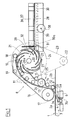
- the device has a first transport path 1 for cut-to-size bank notes 2a, 2b, which are moved from left to left in the illustration according to FIG. 1 by a known chain conveyor C with push fingers, not shown, as described, for example, in DD-A-154070 be transported on the right.
- a separating device 3 is arranged, which has a deflector 3a in the form of a deflection plate, which is pivotally mounted at one of its ends on a horizontal axis 4 lying transversely to the conveying direction.
- This baffle plate is provided with an extension 3b which is oriented approximately perpendicular to its plane and is kinematically connected to a bistable electromagnetic device 6 which allows the deflector 3a to be pivoted between a rest position 5a and a deflection position 5b.
- the deflector 3a In the rest position 5a shown in broken lines, the deflector 3a is located completely below the level of the transport route 1, while in the inclined deflection position 5b it crosses the level of the transport route 1 and tangentially directs a value note 2a coming from the left towards a second transport route, which later is described.
- the bistable electromagnetic device 6, which can also be another equivalent device, is controlled by a detector, not shown, which is installed on the transport path 1 in the conveying direction in front of the separating device 3.
- This detector responds when a note 2a, for example marked with a fluorescent color or another known material, is moved past it, and emits a signal so that the deflector 3a deflects the marked note 2a to the second transport route. As soon as the note has reached the second transport route, the deflector 3a returns to its rest position 5a.
- a first belt arrangement 7 and a second belt arrangement 8 are provided, which have a pair of interacting endless belts 12, 16.
- the first belt arrangement 7 includes the endless belt 12, two end rollers 9 and 10 and a plurality of rollers 11 arranged between them, which guide the belt 12, and a roller 13 which drives this belt 12 by friction.
- rollers 14 and 15 deflecting the belt 12 and pressing against this roller 13 are provided on both sides of the roller 13.
- the second belt arrangement 8 has an endless belt 16 which is guided by two end rollers 17 and 18 and an intermediate roller 19 which keep the lower and the upper run of the belt 16 at a distance; Without this roller 19, the upper and lower run of the belt 16 would touch due to the course of the belts.
- the relative position of the belt arrangements 7 and 8 is selected such that the two endless belts 12 and 16 lie on one another in contact with one another along a path forming the second transport path.
- This second transport route begins between the end rollers 9 and 17 above the separating device 3, in the extension of the deflector 3a taking up its deflection position, runs along a curved path upwards and ends between the end rollers 10 and 18.
- a storage wheel which consists of a plurality of disks 20 which are arranged at an axial distance from one another and which rotate on one horizontal shaft 20a sit.
- Each disk 20 has spiral slits 21 which extend from the inner disk area to the disk circumference and open there approximately tangentially to this circumference.
- the slots located in the same angular ranges of the adjacent disks 20 form receiving openings for the notes of value leaving the second transport path.
- the end of this transport route that is to say the end of the curved path traversed by the notes of value, is oriented at least approximately tangentially to the circumference of the disks 20 and thus to the mouth of the slots 21, which are in their extension when passing the end of the second transport route.
- a drive pulley 22 which drives a pulley 24, which is non-rotatably seated on the shaft 20a, by means of a belt 23.
- the endless belt 12 is driven by a further belt 25, which has a pulley 27, which is also non-rotatably seated on the shaft 20a, and a pulley which is non-rotatably seated on the axis of the roller 13 26 runs.
- the endless belt 16 is driven in such a way that it is entrained by the endless belt 12 due to friction.
- a separate drive for the endless belt 16 can also be provided.
- the ratio of the diameters of the pulleys 24, 26 and 27 is chosen so that the peripheral speed of the pulleys 20 is the speed of the endless belts 12 and 16 and consequently the conveying speed of the belts tated notes of value is adapted such that each note of value arriving at the end of the second transport route reaches one of the slots 21 of the storage wheel.
- the conveying speed of the notes of value along the second transport route is equal to or at least compatible with the conveying speed of the notes of value on the first transport route 1.
- ribbed belts and toothed rollers or pulleys are preferably used.
- the ratio of the diameters of the pulleys 22 and 24 to 1: 4.5 and the ratio of the diameters of the pulleys 27 and 26 to 7.2: 1 are selected.
- a magazine On the circumference of the storage wheel, approximately offset by an angle of 90 ° with respect to the end of the second transport section with the belt arrangements 7, 8, a magazine is arranged which essentially has a horizontal base plate 28 and a plate-shaped stop 29 oriented perpendicularly to this .
- This stop 29 is mounted by means of a sleeve 31 on a shaft 30 installed under the base plate 28 and is displaceable thereon.
- the sleeve 31 is subject to the action of a pressing member 30a, in the example considered a spring which presses the stop 29 in the direction of the end of the base plate 28 adjacent to the storage wheel (FIGS. 1 and 2).
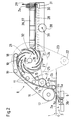
- An inclined plate 32 fastened at the beginning of the magazine is provided with projections which engage between the disks 20 and form deflection members 32a (FIG. 4) crossing the slots 21.
- the notes of value located in the slots 21 of the disks 20 After they have undergone a rotation of approximately 90 ° with the storage wheel, their edge abuts against the deflection members 32a, is stopped there and then approximately upright during the rotation of the storage wheel from the rear slot edges in the direction of rotation and the adjacent peripheral sections of the disks 20 Position out of the slots 21 and pressed against the stop 29 of the magazine, which is pushed against the action of the spring under the thrust of the successively arriving notes. In this way, the separated notes of value on the base plate 28, standing upright, form a horizontal stack (FIG. 2).
- the magazine In order to hold and guide the stacked notes of value 2a laterally, the magazine has two side plates 36 and 37 which are oriented perpendicular to the base plate 28 and are arranged parallel and at a distance from one another. So that their distance can be adjusted to the width of the notes of value, a screw 39 is provided which is connected to a wheel 38 and which engages in two screw nuts (not shown) which are each fastened to one of the two side plates 36 and 37. By turning the wheel 38, the side plates are shifted in opposite directions to adjust them to the width of the notes of value.
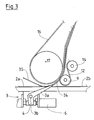
- a curved guide plate 34 (FIG. 3) is provided at the level of the two end rollers 9 and 17, which are in the extension of the deflector 3a lies when it takes up its deflection position 5a, so that the front end raised by the deflector 3a Werteins 2a is guided between the two endless belts 12 and 16; the point at which the two endless belts 12 and 16 begin to touch between the rollers 9 and 17 cannot be moved very close to the branching point of the rejection device.
- a curved plate or another similar element is provided as a guide element 35 which pushes this note against the plane the first transport route 1 presses. This prevents the relevant note from losing contact with the chain conveyor due to the stiffness of the paper when its front end is raised by the deflector 3a.
- the perfect banknotes 2b are moved further on the chain conveyor C.
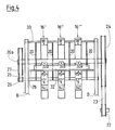
- FIG. 4 shows a preferred embodiment of the device according to the invention, in which instead of a pair of endless belts 12, 16, three pairs of endless belts 12 ', 16'; 12 ⁇ , 16 ⁇ and 12 ′′′, 16 ′′′ and a storage wheel consisting of four disks 20 are provided.
- the belts are driven and guided by a corresponding number of rollers in a manner similar to that described with reference to FIG. 1.
- 4 shows schematically the shaft 20a mounted in a frame B with the four disks 20 of the storage wheel and the pulleys 24, 27, the end rollers 18 ', 18 ⁇ and 18 ′′′, which sit on a shaft 33 also mounted in the frame B.
- the invention is not limited to the exemplary embodiment described, but rather permits multiple variants with regard to the design of all parts and their drive.
Landscapes
- Engineering & Computer Science (AREA)
- Mechanical Engineering (AREA)
- Physics & Mathematics (AREA)
- General Physics & Mathematics (AREA)
- Pile Receivers (AREA)
- Delivering By Means Of Belts And Rollers (AREA)
- Separation, Sorting, Adjustment, Or Bending Of Sheets To Be Conveyed (AREA)
- Discharge By Other Means (AREA)
Applications Claiming Priority (2)
| Application Number | Priority Date | Filing Date | Title |
|---|---|---|---|
| CH4743/87 | 1987-12-04 | ||
| CH4743/87A CH674353A5 (fr) | 1987-12-04 | 1987-12-04 |
Publications (2)
| Publication Number | Publication Date |
|---|---|
| EP0319476A2 true EP0319476A2 (fr) | 1989-06-07 |
| EP0319476A3 EP0319476A3 (fr) | 1990-06-06 |
Family
ID=4281742
Family Applications (1)
| Application Number | Title | Priority Date | Filing Date |
|---|---|---|---|
| EP88810805A Withdrawn EP0319476A3 (fr) | 1987-12-04 | 1988-11-24 | Dispositif de triage et d'empilage de valeurs notamment de billets de banque |
Country Status (6)
| Country | Link |
|---|---|
| US (1) | US4915371A (fr) |
| EP (1) | EP0319476A3 (fr) |
| JP (1) | JPH01162670A (fr) |
| CH (1) | CH674353A5 (fr) |
| DD (1) | DD276175A5 (fr) |
| SU (1) | SU1679978A3 (fr) |
Cited By (3)
| Publication number | Priority date | Publication date | Assignee | Title |
|---|---|---|---|---|
| GB2242185A (en) * | 1990-03-20 | 1991-09-25 | Fima Spa | Feeding, turning and stacking sheet material |
| EP0465874A1 (fr) * | 1990-07-13 | 1992-01-15 | Fraunhofer-Gesellschaft Zur Förderung Der Angewandten Forschung E.V. | Dispositif d'accumulation et d'empilage d'objets plats |
| WO2015197585A1 (fr) | 2014-06-24 | 2015-12-30 | Dsm Ip Assets B.V. | Nouveaux catalyseurs de méthylation |
Families Citing this family (23)
| Publication number | Priority date | Publication date | Assignee | Title |
|---|---|---|---|---|
| US5201504A (en) * | 1988-08-26 | 1993-04-13 | Bell & Howell Company | On-edge stacker |
| US5180160A (en) * | 1991-08-12 | 1993-01-19 | Heidelberg Harris Gmbh | Delivery device in the folding apparatus of a rotary printing press |
| DE4316413A1 (de) * | 1993-05-17 | 1994-11-24 | Heidelberger Druckmasch Ag | Einrichtung zur Entnahme von Probeexemplaren an Rotationsquerschneidern |
| US5359929A (en) * | 1993-08-25 | 1994-11-01 | Rockwell International Corporation | Device for delivering signatures in a printing press |
| US5467976A (en) * | 1994-10-13 | 1995-11-21 | Doucet; Louis J. | Device including a diverting mechanism for changing the conveying direction of products in a folder |
| US5524876A (en) * | 1994-12-22 | 1996-06-11 | F. L. Smithe Machine Company, Inc. | Method and apparatus for delivering and stacking envelopes in an envelope machine |
| US5803705A (en) * | 1997-04-03 | 1998-09-08 | Xerox Corporation | Disk type inverter-stacker with improved sheet handling slots for different paper weights |
| USD419183S (en) * | 1998-03-16 | 2000-01-18 | Stouffer Industries, Inc. | Locking hub |
| US6302393B1 (en) * | 1998-09-17 | 2001-10-16 | Diebold, Incorporated | Media storage system for automated banking machine |
| US6231044B1 (en) | 1998-12-29 | 2001-05-15 | Quad/Tech, Inc. | Delivery apparatus for a printing press |
| DE10014440A1 (de) * | 2000-03-23 | 2001-09-27 | Giesecke & Devrient Gmbh | Blattbearbeitungsvorrichtung und Verfahren zum Einrichten einer Blattbearbeitungsvorrichtung |
| JP2002211824A (ja) * | 2001-01-19 | 2002-07-31 | Hitachi Ltd | 紙葉類取扱装置 |
| US6832886B2 (en) | 2001-07-27 | 2004-12-21 | C. G. Bretting Manufacturing Co., Inc. | Apparatus and method for stacking sheets discharged from a starwheel assembly |
| US7470102B2 (en) * | 2001-07-27 | 2008-12-30 | C.G. Bretting Manufacturing Co., Inc. | Apparatus and method for insertion of separating means into a forming stack of sheets discharged from a starwheel assembly |
| US6877740B2 (en) * | 2003-07-30 | 2005-04-12 | C.G. Bretting Manufacturing Company, Inc. | Starwheel feed apparatus and method |
| KR100608078B1 (ko) * | 2004-07-16 | 2006-08-08 | 엘지엔시스(주) | 매체자동지급기 |
| ATE467516T1 (de) | 2006-12-15 | 2010-05-15 | Kba Giori Sa | Schutzbeschichtung für gedruckte sicherheiten |
| EP1980393A1 (fr) | 2007-04-13 | 2008-10-15 | Kba-Giori S.A. | Procédé et système de production de documents de sécurité |
| EP2189407A1 (fr) | 2008-11-21 | 2010-05-26 | Kba-Giori S.A. | Procédé et système de traitement de feuilles imprimées, spécialement des feuilles de sécurités imprimées, dans des documents individuels |
| US9342944B2 (en) * | 2010-06-07 | 2016-05-17 | Glory Ltd. | Paper-sheet storing/feeding machine, paper-sheet handling machine and method for storing paper sheets |
| JP6189124B2 (ja) | 2013-07-24 | 2017-08-30 | グローリー株式会社 | 紙葉類集積機構および紙葉類処理装置 |
| CN103714614A (zh) * | 2013-12-26 | 2014-04-09 | 上海古鳌电子科技股份有限公司 | 一种纸币清分机出钞结构 |
| CN106127937B (zh) * | 2016-08-18 | 2022-02-08 | 厦门大学嘉庚学院 | 纸币分类机及使用方法 |
Family Cites Families (14)
| Publication number | Priority date | Publication date | Assignee | Title |
|---|---|---|---|---|
| GB190921958A (en) * | 1909-09-27 | 1910-08-25 | Frederick William Musgrave | Improvements in or in connection with Delivery Apparatus for Delivering Envelopes, Cards and the like from High Speed Cylinder Printing Machines. |
| US2294649A (en) * | 1940-07-26 | 1942-09-01 | Dexter Folder Co | Method of and apparatus for handling sheets |
| DE1248561B (de) * | 1961-04-10 | 1967-08-24 | Sperry Rand Corp | Stapelvorrichtung |
| JPS5153041Y2 (fr) * | 1972-12-25 | 1976-12-18 | ||
| JPS5853738B2 (ja) * | 1975-11-11 | 1983-12-01 | 松下電器産業株式会社 | カネンセイガスケンチソシ |
| JPS5313694U (fr) * | 1976-07-16 | 1978-02-04 | ||
| DE2844954A1 (de) * | 1977-10-19 | 1979-04-26 | De La Rue Crosfield | Vorrichtung zum stapeln flexibler boegen |
| JPS5741780A (en) * | 1980-08-26 | 1982-03-09 | Tokyo Shibaura Electric Co | Money note sorting and summing machine |
| JPS58106675A (ja) * | 1981-12-21 | 1983-06-25 | 武蔵株式会社 | 紙幣選別計数機 |
| JPS5894068U (ja) * | 1981-12-21 | 1983-06-25 | 武蔵株式会社 | 紙幣の表裏整理装置 |
| JPS5930186A (ja) * | 1982-08-06 | 1984-02-17 | インタ−ナシヨナル ビジネス マシ−ンズ コ−ポレ−シヨン | 自動預金・支払装置用紙幣収納機構 |
| US4461468A (en) * | 1982-09-23 | 1984-07-24 | Burroughs Corporation | Automatic apparatus for lifting and separating sheet items from the surface of an electrophotographic drum |
| US4570801A (en) * | 1984-03-21 | 1986-02-18 | Brannen Ralph L | Document handling machine |
| JPS6175746A (ja) * | 1985-08-22 | 1986-04-18 | Toshiba Corp | 入出金装置 |
-
1987
- 1987-12-04 CH CH4743/87A patent/CH674353A5/fr not_active IP Right Cessation
-
1988
- 1988-11-03 US US07/266,833 patent/US4915371A/en not_active Expired - Fee Related
- 1988-11-14 JP JP63285933A patent/JPH01162670A/ja active Pending
- 1988-11-17 SU SU884356807A patent/SU1679978A3/ru active
- 1988-11-24 EP EP88810805A patent/EP0319476A3/fr not_active Withdrawn
- 1988-12-02 DD DD88322552A patent/DD276175A5/de not_active IP Right Cessation
Cited By (3)
| Publication number | Priority date | Publication date | Assignee | Title |
|---|---|---|---|---|
| GB2242185A (en) * | 1990-03-20 | 1991-09-25 | Fima Spa | Feeding, turning and stacking sheet material |
| EP0465874A1 (fr) * | 1990-07-13 | 1992-01-15 | Fraunhofer-Gesellschaft Zur Förderung Der Angewandten Forschung E.V. | Dispositif d'accumulation et d'empilage d'objets plats |
| WO2015197585A1 (fr) | 2014-06-24 | 2015-12-30 | Dsm Ip Assets B.V. | Nouveaux catalyseurs de méthylation |
Also Published As
| Publication number | Publication date |
|---|---|
| AU605642B2 (en) | 1991-01-17 |
| DD276175A5 (de) | 1990-02-14 |
| CH674353A5 (fr) | 1990-05-31 |
| US4915371A (en) | 1990-04-10 |
| AU2455288A (en) | 1989-06-08 |
| EP0319476A3 (fr) | 1990-06-06 |
| SU1679978A3 (ru) | 1991-09-23 |
| JPH01162670A (ja) | 1989-06-27 |
Similar Documents
| Publication | Publication Date | Title |
|---|---|---|
| EP0319476A2 (fr) | Dispositif de triage et d'empilage de valeurs notamment de billets de banque | |
| EP0559846B2 (fr) | Dispositif pour le retournement d'une feuille avec changement simultane du sens de transport | |
| DE3134952C2 (de) | Vorrichtung zum Sammeln und Ausgeben von Papierblättern, insbesondere Banknoten in einem Banknotenausgabegerät | |
| DE4116566C2 (de) | Vereinzelungsvorrichtung | |
| DE4029278C2 (fr) | ||
| DE1802760B2 (de) | Stapelvorrichtung für Druckerzeugnisse, insbesondere Zeitungen | |
| EP0946402A1 (fr) | Dispositif pour separer des feuilles d'une pile de feuilles | |
| DE69403540T2 (de) | Vorrichtung zum Zusammentragen von Bögen mit übereinander angeordneten Fächern. | |
| CH665411A5 (de) | Zusammentragmaschine. | |
| EP0371219B1 (fr) | Dispositif pour empiler des produits imprimés substantiellement quadrangulaires et arrivant en continu | |
| DE10059005A1 (de) | Blattablagevorrichtung | |
| DE3839304C2 (fr) | ||
| DE2114865A1 (de) | Vorrichtung zum geschuppten Über einanderlegen von Bogen oder Bogen stapeln | |
| DE2737558C2 (de) | Blattvereinzelungsgerät | |
| DE69621328T2 (de) | Stapelmaschine für poststücke | |
| DE4207069C2 (de) | Vorrichtung zum Leiten von Blättern auf eine Ablagefläche | |
| DE2326929B2 (de) | Vorrichtung zur Zuführung von Kartonagen u.dgl. Rohlingen | |
| DE2816371A1 (de) | Schnelle sortimenterstellung von schriftstuecken, insbesondere banknoten | |
| DE3616804C2 (fr) | ||
| WO1998004484A1 (fr) | Dispositif de separation a interstice de separation reglable | |
| EP0195915A2 (fr) | Dispositif pour empiler des bandes de feuilles pliées en accordéon | |
| DE3122585C2 (de) | Vorrichtung zum Entnehmen von Filmen, insbesondere Röntgenfilmen aus einem Magazin | |
| EP1868931B1 (fr) | Dispositif de regroupement | |
| DE2735721C3 (de) | Vorrichtung zum Abteilen eines Teilstapels von einem Gesamtstapel | |
| DE2334551A1 (de) | Blattfoerdervorrichtung |
Legal Events
| Date | Code | Title | Description |
|---|---|---|---|
| PUAI | Public reference made under article 153(3) epc to a published international application that has entered the european phase |
Free format text: ORIGINAL CODE: 0009012 |
|
| AK | Designated contracting states |
Kind code of ref document: A2 Designated state(s): AT CH DE FR GB IT LI SE |
|
| PUAL | Search report despatched |
Free format text: ORIGINAL CODE: 0009013 |
|
| AK | Designated contracting states |
Kind code of ref document: A3 Designated state(s): AT CH DE FR GB IT LI SE |
|
| RHK1 | Main classification (correction) |
Ipc: B65H 29/62 |
|
| 17P | Request for examination filed |
Effective date: 19901030 |
|
| 17Q | First examination report despatched |
Effective date: 19920414 |
|
| STAA | Information on the status of an ep patent application or granted ep patent |
Free format text: STATUS: THE APPLICATION IS DEEMED TO BE WITHDRAWN |
|
| 18D | Application deemed to be withdrawn |
Effective date: 19920825 |