EP0319499A1 - Machine à écorcer à anneau pour troncs d'arbres - Google Patents
Machine à écorcer à anneau pour troncs d'arbres Download PDFInfo
- Publication number
- EP0319499A1 EP0319499A1 EP88850396A EP88850396A EP0319499A1 EP 0319499 A1 EP0319499 A1 EP 0319499A1 EP 88850396 A EP88850396 A EP 88850396A EP 88850396 A EP88850396 A EP 88850396A EP 0319499 A1 EP0319499 A1 EP 0319499A1
- Authority
- EP
- European Patent Office
- Prior art keywords
- debarking
- edge
- log
- seat
- debarking means
- Prior art date
- Legal status (The legal status is an assumption and is not a legal conclusion. Google has not performed a legal analysis and makes no representation as to the accuracy of the status listed.)
- Granted
Links
- 238000007514 turning Methods 0.000 claims abstract description 3
- 230000001154 acute effect Effects 0.000 claims description 2
- 239000011324 bead Substances 0.000 claims description 2
- 210000002832 shoulder Anatomy 0.000 description 5
- 229910000831 Steel Inorganic materials 0.000 description 2
- 230000000875 corresponding effect Effects 0.000 description 2
- 238000004519 manufacturing process Methods 0.000 description 2
- 239000010959 steel Substances 0.000 description 2
- 229910001347 Stellite Inorganic materials 0.000 description 1
- 229910045601 alloy Inorganic materials 0.000 description 1
- 239000000956 alloy Substances 0.000 description 1
- 238000005219 brazing Methods 0.000 description 1
- AHICWQREWHDHHF-UHFFFAOYSA-N chromium;cobalt;iron;manganese;methane;molybdenum;nickel;silicon;tungsten Chemical compound C.[Si].[Cr].[Mn].[Fe].[Co].[Ni].[Mo].[W] AHICWQREWHDHHF-UHFFFAOYSA-N 0.000 description 1
- 239000011796 hollow space material Substances 0.000 description 1
Images


Classifications
-
- B—PERFORMING OPERATIONS; TRANSPORTING
- B27—WORKING OR PRESERVING WOOD OR SIMILAR MATERIAL; NAILING OR STAPLING MACHINES IN GENERAL
- B27L—REMOVING BARK OR VESTIGES OF BRANCHES; SPLITTING WOOD; MANUFACTURE OF VENEER, WOODEN STICKS, WOOD SHAVINGS, WOOD FIBRES OR WOOD POWDER
- B27L1/00—Debarking or removing vestiges of branches from trees or logs; Machines therefor
- B27L1/04—Debarking or removing vestiges of branches from trees or logs; Machines therefor by rubbing the trunks in rotating drums
- B27L1/05—Drums therefor
-
- Y—GENERAL TAGGING OF NEW TECHNOLOGICAL DEVELOPMENTS; GENERAL TAGGING OF CROSS-SECTIONAL TECHNOLOGIES SPANNING OVER SEVERAL SECTIONS OF THE IPC; TECHNICAL SUBJECTS COVERED BY FORMER USPC CROSS-REFERENCE ART COLLECTIONS [XRACs] AND DIGESTS
- Y10—TECHNICAL SUBJECTS COVERED BY FORMER USPC
- Y10T—TECHNICAL SUBJECTS COVERED BY FORMER US CLASSIFICATION
- Y10T407/00—Cutters, for shaping
- Y10T407/19—Rotary cutting tool
- Y10T407/1906—Rotary cutting tool including holder [i.e., head] having seat for inserted tool
- Y10T407/1934—Rotary cutting tool including holder [i.e., head] having seat for inserted tool with separate means to fasten tool to holder
- Y10T407/1936—Apertured tool
-
- Y—GENERAL TAGGING OF NEW TECHNOLOGICAL DEVELOPMENTS; GENERAL TAGGING OF CROSS-SECTIONAL TECHNOLOGIES SPANNING OVER SEVERAL SECTIONS OF THE IPC; TECHNICAL SUBJECTS COVERED BY FORMER USPC CROSS-REFERENCE ART COLLECTIONS [XRACs] AND DIGESTS
- Y10—TECHNICAL SUBJECTS COVERED BY FORMER USPC
- Y10T—TECHNICAL SUBJECTS COVERED BY FORMER US CLASSIFICATION
- Y10T407/00—Cutters, for shaping
- Y10T407/22—Cutters, for shaping including holder having seat for inserted tool
- Y10T407/2272—Cutters, for shaping including holder having seat for inserted tool with separate means to fasten tool to holder
- Y10T407/2274—Apertured tool
Definitions
- the invention relates to a debarking means for rotation ring type barking machines, and of the type comprising a plurality of swinging arms yieldably engaging the circumference of an unbarked log and each formed at its free end with a seat for a debarking means detachably mounted by means of a bolt connection and having a leading edge serving as a cutting edge, a trailing support edge or surface adapted to engage a shoulder on the seat to prevent turning of said debarking means relative to the arm, and two side edges extending between said leading and trailing edges.
- Barking machines of the above-mentioned type basically operate in such a manner that the individual log is fed lengthwise through the hollow space of a rotor on the inside of which the swinging arms are hingedly mounted, at the same time as the rotor is caused to rotate, the arms and the debarking means thereon being yieldably urged against the circumference of the log by means of suitable spring means enabling the debarking means to follow any irregularities of the log surface.
- the debarking means follow helical paths of motion along the log circumference and remove the bark down to the cambium layer thereof.
- the rate at which the log is fed lengthwise through the rotor must not exceed a given rotational speed of the rotor since otherwise unworked bark portions would be left on the log.
- the maximum rotor speed determines the maximum rate at which the logs are fed lengthwise through the machine and thus the machine output.
- a feature common to prior art debarking means of the detachable type is that they have generally been in the form of an essentially square or otherwise equilateral plate or plate-like body which in itself has no little mass and, furthermore, must be firmly and reliably attached to securely hold the plate in the seat without any tendency to dislodge itself.
- the bolt and washer of the bolt connection must be made fairly heavy, and also the parts of the swinging arm defining the seat must be strongly dimensioned.
- the present invention aims at making it possible to increase the production output of rotation ring type barking machines, more particularly by providing a debarking means which requires but an absolute minimum of additional mass for the swinging arms and which therefore permits a marked increase of the rotor speed (and, consequently, an increase of the log feed rate).
- this is achieved in that the two side edges are of different length, and that the trailing support edge or surface extends at an oblique or acute angle toward the leading cutting edge.
- the former By obliquely positioning the support edge relative to the cutting edge, the former obtains, at a given width of the latter, a length which is markedly greater than if the edges were parallel to one another.
- the greater length of the support edge implies that the debarking means can be securely held in the seat, without it being necessary to increase the dimensions of the debarking means or the rest of the swinging arm.
- the oblique angle between the support edge and the cutting edge can amount to 20-40°, suitably 25-35°, and preferably about 30°.
- Reference numeral 1 in Fig. 1 designates a swinging arm in a barking machine
- reference numeral 2 designates a debarking means designed in accordance with the invention
- reference numeral 3 designates a bolt for attaching the said means to the swinging arm.
- the leading free end of the swinging arm 1 is formed with a seat 4 defined by a shoulder 5 and a bottom 6 whose plane is substantially perpendicular to the plane of the shoulder 5.
- the debarking means 2 has a leading edge 7 serving as a cutting edge, and a trailing support edge or surface 8 adapted to engage the shoulder 5 of the seat 4 on the swinging arm.
- the support edge or surface 8 extends obliquely to the cutting edge 7, more particularly along the entire width of the debarking means and between two side edges 9, 10 of said means which are of different length and essentially parallel to one other.
- the oblique angle between the support edge 8 and the cutting edge 7 is about 30°, although in practice is may be either greater or smaller, for example 20-40°, or suitably 25-35°.
- the planar lower side 11 of the means 2 is formed with a projection 12 adapted to snugly fit into a corresponding recess 13 in the seat bottom surface 6.
- the projection 12 is of oblong shape and is defined by two rectilinear mutually parallel long sides merging into semicircular end portions.
- the recess 13 has essentially the same shape and dimensions as the projection 12.
- Extending through the projection is a threaded hole 14 adapted to receive the attachment bolt 3, the head of which is tightened against the lower side of the leading end of the swinging arm 1.
- a heel 15 having a vertical rear face 16 adapted to engage with a vertical front face 17 on the swinging arm.
- the sharp cutting edge 7 is part of an elongate insert member 18 which is secured, for example by brazing, in a recess 19 of the debarking means 2 and which, in per se known manner, has a higher hardness and resistance to wear than the rest of said means.
- the insert part 18 may be made of hard alloy or STELLITE, the rest of the debarking means being made of steel, for example toughened steel which is precision-cast.
- the longer side edge 9 of the two side edges 9, 10 of the debarking means is slightly curved and is that part of the debarking means which is first struck by a log advancing toward the swinging arm and the debarking means. Because of its slightly curved shape, the edge surface 9 will not dig into the leading end of the log, but will release the log end fairly smoothly. It should here be pointed out that the large force to which the debarking means is subjected when struck by the log, will be distributed in an advantageous manner to the swinging arm by the oblique support surface 8 which will divide the force into a fairly large force component directed in the longitudinal direction of the arm and a smaller component perpendicular thereto.
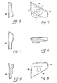
- Figs. 10 and 11 illustrate how the cutting edge 7 of the debarking means extends substantially parallel to the geometrical axis 20 about which the arm 1 pivots.
- the width of the arm 1 has been reduced at 21 in the area behind the shoulder 5 to approximately half the width of the debarking means 2.
- the debarking means according to the invention may have a width of about 50 mm (corresponding to the distance between the two mutually parallel side edges or surfaces 9, 10) so that the cutting edge 7 has a length of about 50 mm. If the oblique angle between the cutting edge 7 and the support surface 8 is about 30°, the length of the support surface will exceed 60 mm. At the same time, the length of the longer side edge 9 is about 50 mm, while the shorter side edge has a length of 15 mm. The thickness of the plate-shaped means, i.e. the distance between the lower side 11 and the upper side 11′, may then be about 7 mm. Naturally, these dimensions may vary considerably, depending upon the size of the machine.
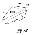
- Fig. 12 shows an alternative embodiment in which the upper side of the debarking means is formed, in the area of the longer side edge 9, with a knife-like bead 22 which has a sharp edge 23 adapted to cut a helical notch in the bark of the log during barking, whereby the risk that the bark is detached from the log in the form of long strips - a risk which occurs especially during barking of trees felled in the spring - is effectively eliminated because the edge 23 cuts the bark into pieces of a length not exceeding the width of the debarking means.
- the oblique position of the rear support surface of the debarking means provides, in combination with the oblong projection on the underside of said means and the heel at the leading end of said means, an exceedingly firm attachment of the debarking means, in spite of the fact that both the debarking means and the associated swinging arm have a relatively small mass. In this manner, the rotor speed can be increased without causing the swinging arms to disengage themselves from the log against the action of the spring means, and this in turn increases the production capacity of the barking machine.
Landscapes
- Life Sciences & Earth Sciences (AREA)
- Engineering & Computer Science (AREA)
- Wood Science & Technology (AREA)
- Forests & Forestry (AREA)
- Debarking, Splitting, And Disintegration Of Timber (AREA)
- Chemical And Physical Treatments For Wood And The Like (AREA)
- Catching Or Destruction (AREA)
- Soil Working Implements (AREA)
- Apparatuses For Bulk Treatment Of Fruits And Vegetables And Apparatuses For Preparing Feeds (AREA)
- Steroid Compounds (AREA)
Priority Applications (1)
| Application Number | Priority Date | Filing Date | Title |
|---|---|---|---|
| AT88850396T ATE61758T1 (de) | 1987-12-01 | 1988-11-17 | Vorrichtung zur rotierenden entrindung von langhoelzern. |
Applications Claiming Priority (2)
| Application Number | Priority Date | Filing Date | Title |
|---|---|---|---|
| SE8704786 | 1987-12-01 | ||
| SE8704786A SE463660B (sv) | 1987-12-01 | 1987-12-01 | Bearbetningsorgan foer barkningsmaskiner av haalrotortyp |
Publications (2)
| Publication Number | Publication Date |
|---|---|
| EP0319499A1 true EP0319499A1 (fr) | 1989-06-07 |
| EP0319499B1 EP0319499B1 (fr) | 1991-03-20 |
Family
ID=20370456
Family Applications (1)
| Application Number | Title | Priority Date | Filing Date |
|---|---|---|---|
| EP88850396A Expired - Lifetime EP0319499B1 (fr) | 1987-12-01 | 1988-11-17 | Machine à écorcer à anneau pour troncs d'arbres |
Country Status (8)
| Country | Link |
|---|---|
| US (1) | US4852622A (fr) |
| EP (1) | EP0319499B1 (fr) |
| AT (1) | ATE61758T1 (fr) |
| CA (1) | CA1316082C (fr) |
| DE (1) | DE3862105D1 (fr) |
| FI (1) | FI84703C (fr) |
| NO (1) | NO166849C (fr) |
| SE (1) | SE463660B (fr) |
Cited By (1)
| Publication number | Priority date | Publication date | Assignee | Title |
|---|---|---|---|---|
| CN103171010A (zh) * | 2011-12-26 | 2013-06-26 | 南京林业大学 | 一种髓弯小径材剥皮刀 |
Families Citing this family (21)
| Publication number | Priority date | Publication date | Assignee | Title |
|---|---|---|---|---|
| SE504338C2 (sv) * | 1994-06-07 | 1997-01-13 | Sandvik Ab | Skärplatta |
| US5460212A (en) * | 1994-06-10 | 1995-10-24 | Darden; Walter C. | Debarking tool with controlled log exiting |
| CA2131066C (fr) * | 1994-08-29 | 2001-01-30 | Denis Johnson | Bras et extremites du dispositif d'ecorcage d'une ecorceuse |
| SE505726C2 (sv) * | 1995-02-27 | 1997-10-06 | Sandvik Ab | Fastspänningsanordning för skärplattor |
| FI98281C (fi) | 1995-06-22 | 1997-05-26 | Valon Kone Oy | Teräpala ja terävarsi reikäroottorityyppisen kuorimakoneen kuorintaterää varten |
| FR2750907B1 (fr) * | 1996-07-12 | 1998-09-18 | Technogenia | Couteau d'ecorcage, et procede pour sa realisation |
| SE511505C2 (sv) * | 1997-09-04 | 1999-10-11 | Iggesund Tools Ab | Bearbetningsverktyg för barkningsmaskin med flera svängarmar |
| USD419854S (en) * | 1998-03-13 | 2000-02-01 | Forano International Inc. | Debarker arm |
| SE510874C2 (sv) | 1998-07-08 | 1999-07-05 | Iggesund Tools Ab | Bearbetningsorgan vid barkningsmaskin |
| USD411097S (en) * | 1998-08-05 | 1999-06-15 | Forano International Inc. | Holder for a debarker arm |
| IL139957A0 (en) * | 2000-11-28 | 2002-02-10 | Iscar Ltd | Cutting tool |
| US6834692B2 (en) | 2002-08-07 | 2004-12-28 | Lindsay Forest Products, Inc. | Log debarking tip |
| KR100488075B1 (ko) * | 2003-04-17 | 2005-05-06 | 엘지전자 주식회사 | 냉장고 도어의 홀더 핸들 구조 |
| AU2003268800A1 (en) * | 2003-10-02 | 2005-04-14 | Iggesund Tools Ab | Barking device and barking tool |
| USD502712S1 (en) * | 2003-10-28 | 2005-03-08 | Iggesund Tools Ab | Debarking tool |
| US7004689B2 (en) * | 2004-01-09 | 2006-02-28 | Kennametal Inc. | High-speed milling cutter and insert |
| US20050173023A1 (en) * | 2004-02-11 | 2005-08-11 | Guofang Cao | Configurations and designs for stump grinding teeth and corresponding holding |
| US7070363B2 (en) | 2004-07-15 | 2006-07-04 | Kennametal Inc. | Cutting insert for high-speed milling cutter |
| US20060284469A1 (en) * | 2005-06-02 | 2006-12-21 | Pride Outdoor Products Group, Inc. | Furniture connector |
| AT508771B1 (de) * | 2009-11-05 | 2011-04-15 | Busatis Gmbh | Messer zur tangentialen entfernung einer oberfläche eines werkstücks |
| EP2650066B1 (fr) * | 2012-04-10 | 2015-06-03 | VARGUS Ltd. | Insert de coupe à fileter, porte-outil et outil pour formation de filetages ultra-résistants |
Citations (3)
| Publication number | Priority date | Publication date | Assignee | Title |
|---|---|---|---|---|
| US4209047A (en) * | 1978-06-28 | 1980-06-24 | Weill Theodore C | Debarker toe assembly |
| US4231406A (en) * | 1977-11-11 | 1980-11-04 | Jonsson Karl Erik A | Device for treatment of the surface of round timber |
| US4368764A (en) * | 1982-01-15 | 1983-01-18 | Wilber Peterson & Sons, Inc. | Rotary multiple log debarker |
Family Cites Families (8)
| Publication number | Priority date | Publication date | Assignee | Title |
|---|---|---|---|---|
| CA551454A (fr) * | 1958-01-14 | J. Greenleaf Walter | Porte-outil coupant | |
| US2880771A (en) * | 1955-03-17 | 1959-04-07 | Improved Machinery Inc | Bark-removing tools mounted on revolving self-opening arms |
| US3026919A (en) * | 1960-04-27 | 1962-03-27 | Sydney Hansel | Log debarkers |
| US3189067A (en) * | 1961-06-16 | 1965-06-15 | Soderhamn Machine Mfg Company | Vacuum operated debarking apparatus |
| US4011049A (en) * | 1975-09-19 | 1977-03-08 | Kennametal Inc. | Method of and device for holding a cutting insert in the pocket of a tool holder |
| US4280541A (en) * | 1980-01-10 | 1981-07-28 | Reimler Associates, Inc. | Debarking tool for log debarking machines |
| DE3211460C2 (de) * | 1982-03-27 | 1985-01-03 | Fried. Krupp Gmbh, 4300 Essen | Klemmvorrichtung für ein Zerspanungswerkzeug |
| US4653559A (en) * | 1985-03-20 | 1987-03-31 | Nicholson Manufacturing Company | Forwardly-projecting debarking tool barker arm |
-
1987
- 1987-12-01 SE SE8704786A patent/SE463660B/sv not_active IP Right Cessation
-
1988
- 1988-11-17 AT AT88850396T patent/ATE61758T1/de not_active IP Right Cessation
- 1988-11-17 EP EP88850396A patent/EP0319499B1/fr not_active Expired - Lifetime
- 1988-11-17 DE DE8888850396T patent/DE3862105D1/de not_active Expired - Fee Related
- 1988-11-21 CA CA000583638A patent/CA1316082C/fr not_active Expired - Fee Related
- 1988-11-22 US US07/274,835 patent/US4852622A/en not_active Expired - Lifetime
- 1988-11-30 FI FI885558A patent/FI84703C/fi not_active IP Right Cessation
- 1988-11-30 NO NO885345A patent/NO166849C/no not_active IP Right Cessation
Patent Citations (3)
| Publication number | Priority date | Publication date | Assignee | Title |
|---|---|---|---|---|
| US4231406A (en) * | 1977-11-11 | 1980-11-04 | Jonsson Karl Erik A | Device for treatment of the surface of round timber |
| US4209047A (en) * | 1978-06-28 | 1980-06-24 | Weill Theodore C | Debarker toe assembly |
| US4368764A (en) * | 1982-01-15 | 1983-01-18 | Wilber Peterson & Sons, Inc. | Rotary multiple log debarker |
Cited By (1)
| Publication number | Priority date | Publication date | Assignee | Title |
|---|---|---|---|---|
| CN103171010A (zh) * | 2011-12-26 | 2013-06-26 | 南京林业大学 | 一种髓弯小径材剥皮刀 |
Also Published As
| Publication number | Publication date |
|---|---|
| FI84703B (fi) | 1991-09-30 |
| NO885345L (no) | 1989-06-02 |
| SE8704786D0 (sv) | 1987-12-01 |
| NO885345D0 (no) | 1988-11-30 |
| NO166849C (no) | 1991-09-11 |
| EP0319499B1 (fr) | 1991-03-20 |
| ATE61758T1 (de) | 1991-04-15 |
| SE8704786L (sv) | 1989-06-02 |
| SE463660B (sv) | 1991-01-07 |
| NO166849B (no) | 1991-06-03 |
| US4852622A (en) | 1989-08-01 |
| DE3862105D1 (de) | 1991-04-25 |
| FI885558L (fi) | 1989-06-02 |
| FI84703C (fi) | 1992-01-10 |
| CA1316082C (fr) | 1993-04-13 |
| FI885558A0 (fi) | 1988-11-30 |
Similar Documents
| Publication | Publication Date | Title |
|---|---|---|
| EP0319499B1 (fr) | Machine à écorcer à anneau pour troncs d'arbres | |
| US6702527B2 (en) | Cutting tool assembly | |
| US4209047A (en) | Debarker toe assembly | |
| US5211212A (en) | Cutting tooth | |
| US4771718A (en) | Chipper disc and knife assembly | |
| US8061396B2 (en) | Tooth for a circular saw or mower drum | |
| CA2084013C (fr) | Dent pour scie circulaire | |
| EP0502863B1 (fr) | Piece coupante et bloc de montage | |
| CA2131066C (fr) | Bras et extremites du dispositif d'ecorcage d'une ecorceuse | |
| EP1013364B1 (fr) | Assemblage de porte-outil | |
| US4759394A (en) | Stump cutting tooth structure | |
| US5088371A (en) | Saw tooth and holder | |
| CA2396919A1 (fr) | Plaquette pour ecorceur | |
| US20020112590A1 (en) | Tree felling disc saw with replaceable teeth | |
| FI103772B (fi) | Teräpala puuntyöstökonetta varten | |
| WO1991000169A1 (fr) | Lame debrouissailleuse amelioree | |
| US20060208120A1 (en) | Chipper knife | |
| US4384600A (en) | Chipping knifer | |
| CA2178697A1 (fr) | Dispositif d'equarrissage | |
| CA2650154C (fr) | Dent pour scie circulaire ou tambour de faucheuse | |
| CA1130087A (fr) | Porte-lame d'ecorceur | |
| JPH0211131Y2 (fr) | ||
| GB2330794A (en) | Woodworking router with replaceable blades. | |
| SE470206B (sv) | Barkningsverktyg för barkningsmaskiner av hålrotortyp | |
| JPH0553902U (ja) | 木工用ルータ刃物 |
Legal Events
| Date | Code | Title | Description |
|---|---|---|---|
| PUAI | Public reference made under article 153(3) epc to a published international application that has entered the european phase |
Free format text: ORIGINAL CODE: 0009012 |
|
| AK | Designated contracting states |
Kind code of ref document: A1 Designated state(s): AT DE FR |
|
| 17P | Request for examination filed |
Effective date: 19890415 |
|
| 17Q | First examination report despatched |
Effective date: 19900627 |
|
| GRAA | (expected) grant |
Free format text: ORIGINAL CODE: 0009210 |
|
| AK | Designated contracting states |
Kind code of ref document: B1 Designated state(s): AT DE FR |
|
| REF | Corresponds to: |
Ref document number: 61758 Country of ref document: AT Date of ref document: 19910415 Kind code of ref document: T |
|
| REF | Corresponds to: |
Ref document number: 3862105 Country of ref document: DE Date of ref document: 19910425 |
|
| ET | Fr: translation filed | ||
| PLBE | No opposition filed within time limit |
Free format text: ORIGINAL CODE: 0009261 |
|
| STAA | Information on the status of an ep patent application or granted ep patent |
Free format text: STATUS: NO OPPOSITION FILED WITHIN TIME LIMIT |
|
| 26N | No opposition filed | ||
| PGFP | Annual fee paid to national office [announced via postgrant information from national office to epo] |
Ref country code: AT Payment date: 20011108 Year of fee payment: 14 |
|
| PGFP | Annual fee paid to national office [announced via postgrant information from national office to epo] |
Ref country code: FR Payment date: 20011113 Year of fee payment: 14 |
|
| PGFP | Annual fee paid to national office [announced via postgrant information from national office to epo] |
Ref country code: DE Payment date: 20020125 Year of fee payment: 14 |
|
| PG25 | Lapsed in a contracting state [announced via postgrant information from national office to epo] |
Ref country code: AT Free format text: LAPSE BECAUSE OF NON-PAYMENT OF DUE FEES Effective date: 20021117 |
|
| PG25 | Lapsed in a contracting state [announced via postgrant information from national office to epo] |
Ref country code: DE Free format text: LAPSE BECAUSE OF NON-PAYMENT OF DUE FEES Effective date: 20030603 |
|
| PG25 | Lapsed in a contracting state [announced via postgrant information from national office to epo] |
Ref country code: FR Free format text: LAPSE BECAUSE OF NON-PAYMENT OF DUE FEES Effective date: 20030731 |
|
| REG | Reference to a national code |
Ref country code: FR Ref legal event code: ST |