EP0319502B1 - Vorrichtung in einem freitragenden Rahmenteil der Presspartie und/oder Siebpartie einer Papiermaschine - Google Patents
Vorrichtung in einem freitragenden Rahmenteil der Presspartie und/oder Siebpartie einer Papiermaschine Download PDFInfo
- Publication number
- EP0319502B1 EP0319502B1 EP88850405A EP88850405A EP0319502B1 EP 0319502 B1 EP0319502 B1 EP 0319502B1 EP 88850405 A EP88850405 A EP 88850405A EP 88850405 A EP88850405 A EP 88850405A EP 0319502 B1 EP0319502 B1 EP 0319502B1
- Authority
- EP
- European Patent Office
- Prior art keywords
- draw bar
- projecting part
- pull
- paper machine
- another end
- Prior art date
- Legal status (The legal status is an assumption and is not a legal conclusion. Google has not performed a legal analysis and makes no representation as to the accuracy of the status listed.)
- Expired - Lifetime
Links
- 230000008878 coupling Effects 0.000 claims 1
- 238000010168 coupling process Methods 0.000 claims 1
- 238000005859 coupling reaction Methods 0.000 claims 1
- 239000004744 fabric Substances 0.000 abstract description 4
- 238000010276 construction Methods 0.000 description 3
- 230000010355 oscillation Effects 0.000 description 2
- 241001504505 Troglodytes troglodytes Species 0.000 description 1
- 230000001627 detrimental effect Effects 0.000 description 1
- 230000001105 regulatory effect Effects 0.000 description 1
Images

Classifications
-
- D—TEXTILES; PAPER
- D21—PAPER-MAKING; PRODUCTION OF CELLULOSE
- D21F—PAPER-MAKING MACHINES; METHODS OF PRODUCING PAPER THEREON
- D21F7/00—Other details of machines for making continuous webs of paper
- D21F7/001—Wire-changing arrangements
Definitions
- the invention concerns a device in a cantilevered frame part of a press section and/or wire section of a paper machine located in a machine hall, in which a cantilevered beam extends between side frames, said cantilevered beam including a projecting part.
- the beam end at the service side of the paper machine is fixed to the ceiling, wall or floor of the paper machine hall, most commonly by means of massive screws to a projection part on the wall of the paper machine hall.
- the function of said fastening is to support the cantilever beam when said intermediate pieces are opened.
- This prior-art fastening involves certain drawbacks, which come from the fact that the fastening is all the time under tension. This is why, oscillations are spread from the paper machine frame through said fastening to the wall constructions of the paper machine hall, which said oscillations increase the noise level in the paper machine hall, besides other drawbacks.
- the object of the present invention is to provide a novel device by means of which it is possible to avoid the drawbacks discussed above.
- the device of the invention is mainly characterised by the features defined in the characterising clause of appended claim 1. Preferred embodiments of the invention are stated in the appended sub-claims.
- the pre-tensioning of the cantilever beam can be released wren the side frames at the service side have been fixed and when the machine is in normal operation; said pre-tensioning can be switched on by means of the device in accordance with the invention, to operate in the connection when the intermediate pieces in the side frames at the service side have been opened, so that the sag of the cantilever beam should not become disturbingly large.
- Figure A is a schematical transverse vertical sectional view that illustrates a prior-art fastening and pre-tensioning of the end of a cantilever beam in the frame part of a paper machine.
- Fig. A illustrates a prior-art cantilevered frame of a paper machine, e.g. a frame of a press section.
- the frame comprises a transverse cantilever beam 10, in connection with which there are the side frames of the paper machine, whereof the service-side side frame 11 and the operation-side side frame 12 are shown schematically in Fig. A.
- the projection part 10a of the cantilever beam 10 at the operation side is fixed to a projection part 17 on the wall 16 of the paper machine hall. This fixing is carried out through a hole 20 made through the end of the projection part 10a of the beam 10 by means of a draw bar 18.
- the draw bar 18 passes through a box bolster 19 mounted in the building in the machine direction, which said bolster rests against the plane bottom side of the projection part 17.
- the nuts 21 and 22 of the draw bar 18 are, as a rule, tightened permanently so that a suitable permanent support and pre-tensioning are obtained for the beam 10. In this state of tension, the draw bar 18 is subjected to a considerable tensile strain.
- the bar 18 and its nuts 21 and 22 are very robust, so that their opening is not rational, usually hardly even possible, e.g., upon replacement of a press felt.
- Fig. A shows the press roll 13 of the press section, which is mounted on the side frames 11 and 12 by the intermediate of its bearings and axle journals 13a.
- Fig. A shows the loading means, such as loading levers and cylinders, of the press roll 13 schematically, said loading means being denoted with the reference numeral 14.
- the intermediate piece 15 is shown in Fig. A.
- a closed loop of press fabric can be pushed to around the press rolls, guide rolls, and the cantilever beam 10, whereinafter the intermediate pieces 15 etc. are closed and the side frame 11 is locked.
- the fastening 17,18,19,21,22 of the projection part 10a of the beam 10 is not opened, but the cantilever beam 10 has a certain pre-tension all the time, owing to the permanent force F, whose purpose is to reduce the sag of the end of the beam 10 placed at the proximity of the service-side side frame 11 and to make it easier to open the intermediate pieces 15.
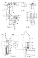
- a hydraulic cylinder 23 Above the projection part 10a of the cantilever beam 10, a hydraulic cylinder 23 is attached, by means of whose piston rod 24 the point C is loaded to the left around the articulation point A of the angular arm 27.
- the lower arm 27b of the angular arm 27 is attached to the draw bar 30 at the point B.
- the necessary pre-tensioning of the beam 10 is produced, whose magnitude can be adjusted by means of the limiter screw 34.
- Fig. 1 The principle of operation and the construction of the embodiment of the invention shown in Fig. 1 are similar to that described above.
- the lower arm 27b of the angular arm 27 is attached to the draw bar 30 by means of the articulated joint 33.
- the draw bar 30 passes through a box bolster 31 mounted in the building in the machine direction.
- the draw bar 30 is fixed by means of nuts 32 in connection with the box bolster 31.
- the construction is similar to that shown in Fig. 2.
- Fig. 2 differs from Fig. 1 in the respect that at the upper end of the draw bar 30 there is a fork 37, which is attached to the lower part 27b of the angular arm 27 at the point B by means of an articulation shaft 33.
- Fig. 4 shows another embodiment of the invention, which differs from the above.
- the piston rod 41 of a draw cylinder 40 is attached to the outer end of the projection part 10a of the cantilever beam 10 by means of brackets 47 and articulation pins 42.
- the draw cylinder 40 is attached to a draw bar 44 by means of an articulation pin 43, said draw bar 44 passing through the box bolster 45 mounted in the building in the machine direction.
- the draw bar 44 transfers the lifting force to the box bolster 45 by means of a nut 46.
- the flange 48 at the top end of the box bolster 45 rests against the lower plane side of the projection part 17 on the wall 16.
- a lifting cylinder 50 or jack is fixed onto the top side of the projection part 10a of the cantilever beam 10, the lifting part 51 of said lifting cylinder being fitted against the lower flange 55 of the box bolster 52 mounted in the building in the machine direction.
- the upper flange 53 of the box bolster 52 rests against the horizontal lower side of the projection part 17 on the wall 16.
- the power units 23,40 and 50 have no pressure p and the cantilever beam is not pre-tensioned in connection with normal operation of the machine.
- the pressure p is passed into the power units 23,40,50, which said pressure has been chosen such that, by means of a mechanism in accordance with the invention, a certain pre-tension of appropriate magnitude is always provided in the cantilever beam 10.
- This pre-tensioning is chosen so that the sag of the end of the cantilever beam 10 placed at the service-side side frame 11 does not become excessively large.
- the pressure p in the power units 23,40,50 does not have to be regulated, but the magnitude of the pre-tensioning force F and the magnitude of the deflection of the projection part 10a of the beam 10 downwards are determined by mechanical devices, such as, in accordance with Figs. 1 and 2, by the limiter 34 provided at the end of the lower part 27b of the angular arm 27, said limiter 34 being, if necessary, arranged adjustable.
Landscapes
- Paper (AREA)
- Manufacture And Refinement Of Metals (AREA)
- Luminescent Compositions (AREA)
- Organic Low-Molecular-Weight Compounds And Preparation Thereof (AREA)
- Inspection Of Paper Currency And Valuable Securities (AREA)
- Accessory Devices And Overall Control Thereof (AREA)
- Pile Receivers (AREA)
Claims (6)
einen Ladehebel (27), der mit dem vorstehenden Teil (10a) des freitragenden Balkens (10) drehbar verbunden ist,
eine Antriebsvorrichtung (23), die zum Aufbringen einer Kraft auf den Ladehebel (27) an dem vorstehenden Teil (10a) des freitragenden Balkens (10) angebracht ist, und
eine Zug-/Hubstange (30), die ein mit dem Ladehebel (27) drehbar verbundenes Ende und ein anderes, mit einem feststehenden Gegenstück verbundenes Ende aufweist.
Priority Applications (1)
| Application Number | Priority Date | Filing Date | Title |
|---|---|---|---|
| AT88850405T ATE74981T1 (de) | 1987-12-03 | 1988-12-02 | Vorrichtung in einem freitragenden rahmenteil der presspartie und/oder siebpartie einer papiermaschine. |
Applications Claiming Priority (2)
| Application Number | Priority Date | Filing Date | Title |
|---|---|---|---|
| FI875332 | 1987-12-03 | ||
| FI875332A FI87093C (fi) | 1987-12-03 | 1987-12-03 | Anordning vid kantileverad stomdel i presspartiet och/eller virapartiet i en pappersmaskin |
Publications (2)
| Publication Number | Publication Date |
|---|---|
| EP0319502A1 EP0319502A1 (de) | 1989-06-07 |
| EP0319502B1 true EP0319502B1 (de) | 1992-04-15 |
Family
ID=8525510
Family Applications (1)
| Application Number | Title | Priority Date | Filing Date |
|---|---|---|---|
| EP88850405A Expired - Lifetime EP0319502B1 (de) | 1987-12-03 | 1988-12-02 | Vorrichtung in einem freitragenden Rahmenteil der Presspartie und/oder Siebpartie einer Papiermaschine |
Country Status (5)
| Country | Link |
|---|---|
| US (1) | US4861431A (de) |
| EP (1) | EP0319502B1 (de) |
| AT (1) | ATE74981T1 (de) |
| DE (1) | DE3870173D1 (de) |
| FI (1) | FI87093C (de) |
Families Citing this family (6)
| Publication number | Priority date | Publication date | Assignee | Title |
|---|---|---|---|---|
| SE9002758D0 (sv) * | 1990-08-29 | 1990-08-29 | Valmet Paper Machinery Inc | A framework for a press in a machine for the manufacture of a fibrous web |
| US5389205A (en) * | 1990-11-23 | 1995-02-14 | Valmet Paper Machinery, Inc. | Method for dewatering of a paper web by pressing using an extended nip shoe pre-press zone on the forming wire |
| DE9206152U1 (de) * | 1992-05-12 | 1992-07-16 | J.M. Voith Gmbh, 7920 Heidenheim | Maschinengestell |
| US5250154A (en) * | 1992-09-17 | 1993-10-05 | Beloit Technologies, Inc. | Quick-release post for a papermaking machine press frame |
| DE4328505C2 (de) * | 1993-08-25 | 1997-04-24 | Voith Gmbh J M | Cantileverbare Walze |
| US20050045299A1 (en) * | 1998-02-06 | 2005-03-03 | Franz Petschauer | Process and a device for the formation of fiberboard |
Family Cites Families (4)
| Publication number | Priority date | Publication date | Assignee | Title |
|---|---|---|---|---|
| GB863452A (en) * | 1958-12-10 | 1961-03-22 | Dorries A G O | Device for fourdrinier paper machines |
| US4140575A (en) * | 1971-08-18 | 1979-02-20 | Escher Wyss Gmbh | Roller frame, particularly for the press portion of a paper machine |
| DE2943974C2 (de) * | 1979-10-31 | 1984-02-16 | J.M. Voith Gmbh, 7920 Heidenheim | Pressenpartie einer Papiermaschine |
| FI810575A7 (fi) * | 1981-02-25 | 1982-08-26 | Valmet Oy | Menetelmä ja laite paperikoneen puristinosan pick-up-kudoksen ja/tai puristinkudoksen vaihtamiseksi. |
-
1987
- 1987-12-03 FI FI875332A patent/FI87093C/fi not_active IP Right Cessation
-
1988
- 1988-11-30 US US07/278,187 patent/US4861431A/en not_active Expired - Fee Related
- 1988-12-02 EP EP88850405A patent/EP0319502B1/de not_active Expired - Lifetime
- 1988-12-02 DE DE8888850405T patent/DE3870173D1/de not_active Expired - Lifetime
- 1988-12-02 AT AT88850405T patent/ATE74981T1/de active
Also Published As
| Publication number | Publication date |
|---|---|
| US4861431A (en) | 1989-08-29 |
| EP0319502A1 (de) | 1989-06-07 |
| FI87093B (fi) | 1992-08-14 |
| FI875332A0 (fi) | 1987-12-03 |
| DE3870173D1 (de) | 1992-05-21 |
| FI87093C (fi) | 1992-11-25 |
| ATE74981T1 (de) | 1992-05-15 |
| FI875332L (fi) | 1989-06-04 |
Similar Documents
| Publication | Publication Date | Title |
|---|---|---|
| US5291826A (en) | Tension bars for roll press for paper making machine | |
| DE69414819T2 (de) | Kupplungskonstruktion zwischen Rollen einer Breit-Nip Presse | |
| US4657634A (en) | Frame construction and method in a paper machine press section for facilitating replacement of press rolls and fabrics | |
| US4560441A (en) | Press section for a paper-making machine having a movable cantilever beam | |
| EP0319502A1 (de) | Vorrichtung in einem freitragenden Rahmenteil der Presspartie und/oder Siebpartie einer Papiermaschine | |
| US5547547A (en) | Compact frame assembly for a press in a papermaking or boardmaking | |
| US5399242A (en) | Machine frame for supporting dewatering elements | |
| KR100424940B1 (ko) | 광택캘린더 | |
| US5207872A (en) | Prestressed press framework for a papermaking machine | |
| US5535670A (en) | Cantileverable roll for roll pair of paper making machine | |
| US4875975A (en) | Device for drawing an endless belt into a paper making machine | |
| JPH0241485A (ja) | 抄紙機のプレス部 | |
| US3515637A (en) | Papermaking machine press section | |
| FI82089C (fi) | Presspartiet i en pappersmaskin och dess stomkonstruktion. | |
| US5250154A (en) | Quick-release post for a papermaking machine press frame | |
| US5558018A (en) | Support frame for nip rollers | |
| US5670022A (en) | Top roll lifting arrangement for a press in a papermaking or boardmaking machine | |
| US5154799A (en) | Method and device in a compact press section of a paper machine for replacement of rolls and fabrics | |
| US5032228A (en) | Method of and an arrangement for supporting the frame of a paper machine | |
| US4948465A (en) | Method and apparatus for facilitating the replacement of an endless press felt in a paper and board making machine | |
| JPH0791797B2 (ja) | 製紙装置 | |
| EP0224461B1 (de) | Verfahren und Chassis in einer Presspartie einer Papiermaschine zum Erleichtern der Auswechselung von Presswalzen und Filzen | |
| FI80136C (fi) | Anordning foer belastning och lyftning av en pressvals. | |
| FI84378C (fi) | Foerfarande vid den kantilevrade stomdelen av pappersmaskinens pressparti och/eller viraparti foer foerspaenning av kantilevringsbalken och en foerspaenningsanlaeggning. | |
| US5127996A (en) | Method and device in a compact press section frame construction of a paper machine |
Legal Events
| Date | Code | Title | Description |
|---|---|---|---|
| PUAI | Public reference made under article 153(3) epc to a published international application that has entered the european phase |
Free format text: ORIGINAL CODE: 0009012 |
|
| AK | Designated contracting states |
Kind code of ref document: A1 Designated state(s): AT DE FR GB IT SE |
|
| 17P | Request for examination filed |
Effective date: 19890701 |
|
| 17Q | First examination report despatched |
Effective date: 19901024 |
|
| GRAA | (expected) grant |
Free format text: ORIGINAL CODE: 0009210 |
|
| AK | Designated contracting states |
Kind code of ref document: B1 Designated state(s): AT DE FR GB IT SE |
|
| PG25 | Lapsed in a contracting state [announced via postgrant information from national office to epo] |
Ref country code: IT Free format text: LAPSE BECAUSE OF FAILURE TO SUBMIT A TRANSLATION OF THE DESCRIPTION OR TO PAY THE FEE WITHIN THE PRE;WARNING: LAPSES OF ITALIAN PATENTS WITH EFFECTIVE DATE BEFORE 2007 MAY HAVE OCCURRED AT ANY TIME BEFORE 2007. THE CORRECT EFFECTIVE DATE MAY BE DIFFERENT FROM THE ONE RECORDED.SCRIBED TIME-LIMIT Effective date: 19920415 Ref country code: FR Effective date: 19920415 Ref country code: AT Effective date: 19920415 |
|
| REF | Corresponds to: |
Ref document number: 74981 Country of ref document: AT Date of ref document: 19920515 Kind code of ref document: T |
|
| REF | Corresponds to: |
Ref document number: 3870173 Country of ref document: DE Date of ref document: 19920521 |
|
| EN | Fr: translation not filed | ||
| PG25 | Lapsed in a contracting state [announced via postgrant information from national office to epo] |
Ref country code: GB Effective date: 19921202 |
|
| PG25 | Lapsed in a contracting state [announced via postgrant information from national office to epo] |
Ref country code: SE Effective date: 19921203 |
|
| PLBE | No opposition filed within time limit |
Free format text: ORIGINAL CODE: 0009261 |
|
| STAA | Information on the status of an ep patent application or granted ep patent |
Free format text: STATUS: NO OPPOSITION FILED WITHIN TIME LIMIT |
|
| 26N | No opposition filed | ||
| GBPC | Gb: european patent ceased through non-payment of renewal fee |
Effective date: 19921202 |
|
| PG25 | Lapsed in a contracting state [announced via postgrant information from national office to epo] |
Ref country code: DE Effective date: 19930901 |
|
| EUG | Se: european patent has lapsed |
Ref document number: 88850405.7 Effective date: 19930709 |