EP0319738A2 - Radiateur à plaques - Google Patents
Radiateur à plaques Download PDFInfo
- Publication number
- EP0319738A2 EP0319738A2 EP88118915A EP88118915A EP0319738A2 EP 0319738 A2 EP0319738 A2 EP 0319738A2 EP 88118915 A EP88118915 A EP 88118915A EP 88118915 A EP88118915 A EP 88118915A EP 0319738 A2 EP0319738 A2 EP 0319738A2
- Authority
- EP
- European Patent Office
- Prior art keywords
- plate
- panel
- heating plate
- cladding
- heating
- Prior art date
- Legal status (The legal status is an assumption and is not a legal conclusion. Google has not performed a legal analysis and makes no representation as to the accuracy of the status listed.)
- Ceased
Links
Images



Classifications
-
- F—MECHANICAL ENGINEERING; LIGHTING; HEATING; WEAPONS; BLASTING
- F24—HEATING; RANGES; VENTILATING
- F24D—DOMESTIC- OR SPACE-HEATING SYSTEMS, e.g. CENTRAL HEATING SYSTEMS; DOMESTIC HOT-WATER SUPPLY SYSTEMS; ELEMENTS OR COMPONENTS THEREFOR
- F24D19/00—Details
- F24D19/06—Casings, cover lids or ornamental panels, for radiators
- F24D19/065—Grids attached to the radiator and covering its top
-
- F—MECHANICAL ENGINEERING; LIGHTING; HEATING; WEAPONS; BLASTING
- F24—HEATING; RANGES; VENTILATING
- F24D—DOMESTIC- OR SPACE-HEATING SYSTEMS, e.g. CENTRAL HEATING SYSTEMS; DOMESTIC HOT-WATER SUPPLY SYSTEMS; ELEMENTS OR COMPONENTS THEREFOR
- F24D19/00—Details
- F24D19/06—Casings, cover lids or ornamental panels, for radiators
-
- F—MECHANICAL ENGINEERING; LIGHTING; HEATING; WEAPONS; BLASTING
- F28—HEAT EXCHANGE IN GENERAL
- F28D—HEAT-EXCHANGE APPARATUS, NOT PROVIDED FOR IN ANOTHER SUBCLASS, IN WHICH THE HEAT-EXCHANGE MEDIA DO NOT COME INTO DIRECT CONTACT
- F28D1/00—Heat-exchange apparatus having stationary conduit assemblies for one heat-exchange medium only, the media being in contact with different sides of the conduit wall, in which the other heat-exchange medium is a large body of fluid, e.g. domestic or motor car radiators
- F28D1/02—Heat-exchange apparatus having stationary conduit assemblies for one heat-exchange medium only, the media being in contact with different sides of the conduit wall, in which the other heat-exchange medium is a large body of fluid, e.g. domestic or motor car radiators with heat-exchange conduits immersed in the body of fluid
- F28D1/03—Heat-exchange apparatus having stationary conduit assemblies for one heat-exchange medium only, the media being in contact with different sides of the conduit wall, in which the other heat-exchange medium is a large body of fluid, e.g. domestic or motor car radiators with heat-exchange conduits immersed in the body of fluid with plate-like or laminated conduits
- F28D1/0308—Heat-exchange apparatus having stationary conduit assemblies for one heat-exchange medium only, the media being in contact with different sides of the conduit wall, in which the other heat-exchange medium is a large body of fluid, e.g. domestic or motor car radiators with heat-exchange conduits immersed in the body of fluid with plate-like or laminated conduits the conduits being formed by paired plates touching each other
- F28D1/0316—Assemblies of conduits in parallel
-
- F—MECHANICAL ENGINEERING; LIGHTING; HEATING; WEAPONS; BLASTING
- F28—HEAT EXCHANGE IN GENERAL
- F28D—HEAT-EXCHANGE APPARATUS, NOT PROVIDED FOR IN ANOTHER SUBCLASS, IN WHICH THE HEAT-EXCHANGE MEDIA DO NOT COME INTO DIRECT CONTACT
- F28D21/00—Heat-exchange apparatus not covered by any of the groups F28D1/00 - F28D20/00
- F28D2021/0019—Other heat exchangers for particular applications; Heat exchange systems not otherwise provided for
- F28D2021/0035—Other heat exchangers for particular applications; Heat exchange systems not otherwise provided for for domestic or space heating, e.g. heating radiators
Definitions
- the invention relates to a plate heater with one or more heating plate (s) composed of two corrugated shells, in which the heating plate of the single-layer heating element or the foremost heating plate of the multi-layer heating plate is visually connected to a further plate.
- the panels of the panel radiators generally have a corrugated surface due to the heating and collecting channels in the panels, which is often undesirable for interior design or aesthetic reasons when the radiators are used in residential and office buildings.
- a flat radiator with a corrugated shell and a flat front plate is also known from DE-GM 83 06 220.
- the profiled plate shell is welded to the flat front plate.
- Welding with the flat plate forming the visible surface can, for example, lead to deformations on the visible surface due to the occurrence of thermal stresses which are unavoidable during welding.
- the final surface finish of the visible surface such as a plastic coating, can only take place after welding, since the visible surface is impaired by the high temperatures during welding would.
- a plate heater in which closed cavities are formed on the front side in order to reduce the convection and reduce the radiation intensity.
- a plate is placed in front of the corrugated visible surface of the radiator. Insulating layers can be arranged between the radiator and the plate, which reduce the heat transfer from the radiator to the front plate. No further details are given in the document about the material of the insulating layer.
- the present invention has for its object to provide a panel radiator with one or more heating plate layers, which is flat on the visible side, so that the aesthetic or interior design reservations against panel radiators can no longer be maintained due to their wavy profiled visible surface.
- the panel radiator to be created should consist of the well-known profiled half-shells, so that on the one hand it can easily be put on the market with the profiled visible surface and on the other hand it can be formed on the visible side by an additional simple operation in the form of an externally flat plate. In this way, flexible adaptation of production to the demand for radiators with a profiled or flat visible side is to be achieved.
- the cladding plate is connected to the heating plate by means of an adhesive layer that is elastic after curing.
- an adhesive layer that is elastic after curing.
- the adhesive layer should naturally have a small thickness, so that the heat transfer from the heating plate to the cladding plate, from which the heat is released to the environment, is little impeded.
- the thickness of the adhesive layer is generally less than 1 mm, preferably 0.03 to 0.5 mm, in particular 0.05 to 0.3 mm.
- the hardened adhesive layer between the heating plate and the cladding plate remains elastic in the temperature range from 10 to 100 ° C. when subjected to temperature changes.
- a temperature resistance of up to 150 ° C can be advantageous for a short time.
- the adhesive layer should also be weather-resistant, since the radiators according to the invention are often used in bathrooms in which high water vapor pressures and fluctuations in humidity can prevail. The slight mutual displacements between the front heating plate and the cladding plate as a result of temperature differences therefore do not lead to embrittlement and destruction of the adhesive layer even after long operating times.
- the adhesive layer is a polyurethane adhesive, elasticized epoxy resin adhesive, polyvinyl chloride plastisol or rubber Adhesive, preferably formed by a polyurethane adhesive, in particular a one-component polyurethane adhesive.
- a suitable one-component polyurethane adhesive is, for example, Sikaflex-221 from Sika Chemie GmbH. However, equivalent polyurethane adhesives from other manufacturers can also be used. Two-component polyurethane adhesives can also be used.
- polyurethane adhesives are the most suitable, epoxy resin adhesives can also be used if they are sufficiently elasticized.
- the epoxy resin adhesives can contain, for example, butadiene-acrylonitrile rubber or polychloroprene.
- the cladding plate is preferably glued to the bead surface of the heating plate protruding from the front, in particular the flat end faces of the heating plate beads.
- the cladding plate is in contact with 30 to 90%, preferably 50 to 80%, of the visible side of the heating plate via the adhesive layer, while an air layer is present between the heating plate and the cladding plate. It has surprisingly been found that the heating power of the plate heater according to the invention decreases only insignificantly, approximately in the order of 3 to 5%, due to the glued-on cladding plate. The reduction in heating capacity is greater with a single-layer panel radiator than with a multi-layer panel radiator.
- the top and side edge region of the cladding panel is preferably bent backwards until it abuts against the welding flange of the outer shell of the outer heating panel, and a cover and side cladding overlaps the edge region of the cladding panel bent in this way. In this way, the panel is also held by the cover and side panels.
- the cover and side cladding of multi-layer panel radiators is known and, just like the cladding panel according to the invention, serves to give the multi-layer panel radiator an elegant, compact appearance so that it can also be used in sophisticated living and office spaces.
- the upper and, if appropriate, the lateral edge region of the cladding panel is angled backward in a U-shape and this edge region extends over the welding edge of the radiator shell.
- This design of the cladding panel not only covers the profiled visible surface of the panel radiator, but also its edge area, so that the result is similar to that of a multilayer panel radiator with front, cover and side panels.
- the cladding panel is expediently angled backwards along the lower edge region.
- the cladding panel expediently consists of a plastic-coated sheet metal panel. It can only be plastic-coated on the front or on both sides.
- the plastic coating can e.g. be formed by powder coating and baking.
- the metal plate without a projection has a thickness in the range from 0.5 to 1.25 mm.
- the cladding plate protrudes at least laterally beyond the outline of the heating plate (s) and an opening for the handle of a regulating valve is formed in the protrusion.
- the regulating valve projecting laterally from the plate heater is also covered by the cladding plate, only the valve handle protruding forward through the cladding plate.
- Cladding panels with such a lateral or upper or lower projection must have a sheet thickness of preferably 1.25 to 1.50 mm in order to give the projection sufficient bending rigidity.
- hooks, holders and / or horizontal bars are attached to the outside of the cladding plate.
- This bathroom radiator is glued according to the invention with a smooth cladding panel that is angled towards the wall.
- the radiator not only has an attractive design due to the smooth surface, but hooks and the like can also be screwed onto the cladding plate in the area of the recesses of the heating plate profiles. The direct attachment of such holding means to the water-bearing profiled plate heater is not possible because of the risk of leakage.
- an electrically heatable rod can be fitted behind the heating plate, in particular in the aforementioned bathroom radiator.
- the panel radiator can optionally be heated electrically, e.g. if the hot water heating is out of order.
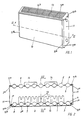
- the plate heater consists of a first front heating plate 1 and a second rear heating plate 2, each of which is welded together from two identical shells 3 and 4 or 5 and 6 arranged in mirror image to one another.
- vertically extending beads are formed in the shells 3 to 6, which form heating channels 7 and 8 of approximately hexagonal cross-section with the beads of the counter shell.
- the heating plates 1 and 2 are connected in a known manner at their four corners by T-shaped pipe sockets (not shown).
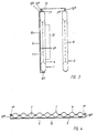
- a steel sheet cladding plate 10 is glued on by means of an adhesive layer 9. From Figure 2 it can be seen that the covering plate 10 is bent in the lateral edge region 10 a to the rear and to the side. Figure 3 also illustrates that the panel 10 in the upper edge region 10 b is also angled backwards and upwards, while the lower Edge area 10 c is simply folded backwards.
- the plate heater is also clad by two side cladding panels 11 and an upper perforated cover plate 12. From Figure 2 it can be seen that the side panel 11 have angled edges 11 a .
- the side cladding plates 11 engage with their angled edges 11 a on the front over the angled lateral edge areas 10 a of the cladding plate 10 and on the back over the welding edge 2 a of the rear heating plate 2.
- the perforated cover plate 12 engages with its angled longitudinal edges 12 a on the front over the angled edge region 10 b of the cladding plate 10 and on the other hand behind the welding edge 2 a of the rear heating plate 2 ( Figure 3).
- the front heating plate 1 bears fins 13 on the back to increase the heating power in a known manner.
- Retaining tabs 14 are welded onto the rear heating plate 2 in a known manner.
- the heating plate 1 likewise consists of the one of the radiator according to FIGS. 1 to 3, of a front shell 3 provided with beads and a rear shell 4 provided with mirror-image beads. Both shells are along their peripheral edges or flanges 1 a welded and spot welded between the beads.
- On the outside of the beads of the shell 3 is glued by means of an elastic adhesive layer 9 of a cladding plate 10, which is bent at the side edges 10 a U-shaped, the rear flange engaging behind the welding edge 1 a of the heating plate 1.
- the upper edge (not shown) is folded so that it can also reach behind the welding edge 1 a .
- the lower edge of the cladding panel 10 is also folded back, as shown in Figure 3.
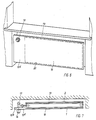
- FIG. 5 shows a single-layer panel radiator 1 with a glued-on cladding plate 10.
- the cladding plate 10 has a left-hand overhang 10 d , which covers the regulating valve 17 and the associated pipeline 18.
- the plate protrusion 10 d is a circular opening 15 through which the handle 16 of the regulating valve 17 protrudes in front of the plate 10.
- the plate 10 has angled lateral and upper edges 10 a and 10 b .
- Figure 6 shows the radiator shown in Figure 5 in a recess 19 below a window sill.
- the outline 20 of the heating plate covered by the plate 10 is shown in dashed lines.
- FIG. 7 shows the top view of a two-layer plate heater arranged in a recess 19, which consists of a front heating plate 1 and a rear heating plate 2.
- a cladding plate 10 with a left-hand, cantilevered projection 10 d is glued on.
- the cladding panel 10 is angled at the edge towards the niche, as is shown in the region of the protrusion 10 d at 10 b .
- the handle 16 of the regulating valve 17 projects outward through the plate protrusion 10 d .
- the bathroom radiator according to the invention shown in Figures 8 and 9 is much higher than it is wide. Hooks 21 are screwed onto the cladding plate 10 in the area of the air ducts between the profiled heating plate and the flat cladding plate, on which, for example, a bathrobe can be hung. Furthermore, 10 rings 22 are screwed onto the plate for hanging up hand or bath towels.
- the rear view according to FIG. 9 shows that an electrically heatable rod 26 is provided behind the heating plate 1, which allows the heating element according to the invention to be heated even when the hot water supply is switched off.
- the trim panel 10 is angled twice on both sides, so that the radiator laterally ge after hanging on a wall is closed.
- the upper cover plate 12 is perforated, however, so that warm air can flow upwards.
- transverse strips of sheet metal 24, 25 are attached to the rear, to which two perforated tabs 27 are fastened.
- the panel radiator is attached to the wall by means of four screws 28, optionally using dowels 29.
- a transverse towel rail 23 that is to say after the radiator has been attached to the wall, is screwed horizontally onto the panel 10.
- the elastomeric adhesive layer 9 after curing ensures that, in the event of inevitable temperature fluctuations between the heating plate 1 and the cladding plate 10, small relative movements between the plate surfaces connected by the adhesive layer 9 are possible without the layer becoming brittle and destroyed over time.
Landscapes
- Engineering & Computer Science (AREA)
- Physics & Mathematics (AREA)
- Thermal Sciences (AREA)
- Mechanical Engineering (AREA)
- General Engineering & Computer Science (AREA)
- Chemical & Material Sciences (AREA)
- Combustion & Propulsion (AREA)
- Central Heating Systems (AREA)
- Domestic Hot-Water Supply Systems And Details Of Heating Systems (AREA)
Applications Claiming Priority (2)
| Application Number | Priority Date | Filing Date | Title |
|---|---|---|---|
| DE8715122U | 1987-11-13 | ||
| DE8715122U DE8715122U1 (de) | 1987-11-13 | 1987-11-13 | Plattenheizkörper |
Publications (2)
| Publication Number | Publication Date |
|---|---|
| EP0319738A2 true EP0319738A2 (fr) | 1989-06-14 |
| EP0319738A3 EP0319738A3 (fr) | 1989-08-09 |
Family
ID=6814088
Family Applications (1)
| Application Number | Title | Priority Date | Filing Date |
|---|---|---|---|
| EP88118915A Ceased EP0319738A3 (fr) | 1987-11-13 | 1988-11-13 | Radiateur à plaques |
Country Status (2)
| Country | Link |
|---|---|
| EP (1) | EP0319738A3 (fr) |
| DE (2) | DE8715122U1 (fr) |
Cited By (2)
| Publication number | Priority date | Publication date | Assignee | Title |
|---|---|---|---|---|
| AT153U1 (de) * | 1994-07-06 | 1995-03-27 | Vogel & Noot Waermetechnik Ag | Heizkoerper, insbesondere stahlheizkoerper und verfahren zu dessen herstellung |
| PL424936A1 (pl) * | 2018-03-19 | 2019-09-23 | Instal-Projekt Gawłowscy Ścierzyńscy Spółka Jawna | Sposób wytwarzania grzejników płytowych |
Families Citing this family (12)
| Publication number | Priority date | Publication date | Assignee | Title |
|---|---|---|---|---|
| DE8809545U1 (de) * | 1988-07-22 | 1988-09-29 | Kermi GmbH, 8350 Plattling | Plattenheizkörper |
| DE8902961U1 (de) * | 1989-03-10 | 1989-05-11 | Kermi GmbH, 8350 Plattling | Heizkörperverkleidung |
| BE1003412A6 (nl) * | 1989-10-06 | 1992-03-17 | Hendrickx Ludovicus | Bekleding voor radiatoren. |
| BE1007165A3 (nl) * | 1991-11-14 | 1995-04-11 | Limeparts Afgekort Lmp | Radiator met een stralingspaneel en daartegen bevestigde verwarmingsbuizen. |
| DE19504408A1 (de) * | 1995-02-10 | 1996-08-14 | Broetje August Gmbh & Co | Verkleidung für einen Heizkörper |
| DE19535280C2 (de) * | 1995-09-22 | 1999-08-26 | Koenig | Heizkörperanordnung |
| AU4381597A (en) | 1996-08-28 | 1998-03-19 | Kermi Gmbh | Heating radiator |
| DE10015581C1 (de) * | 2000-03-29 | 2001-08-16 | Peter Gabanyi | Innenraum-Klimatisierungsvorrichtung |
| GB2391609A (en) * | 2002-07-25 | 2004-02-11 | Jason Harris | Radiator cover |
| DE102008024423B3 (de) * | 2008-05-16 | 2009-12-03 | Kermi Gmbh | Verfahren zur Herstellung eines Heizkörpers mit einer Heizkörperabdeckung |
| DE102014103073A1 (de) | 2014-03-07 | 2015-09-10 | H.M. Heizkörper GmbH + Co. KG | Flachheizkörper |
| FR3030692B1 (fr) * | 2014-12-23 | 2019-05-03 | Atlantic Industrie | Appareil de chauffage a facade suspendue |
Family Cites Families (9)
| Publication number | Priority date | Publication date | Assignee | Title |
|---|---|---|---|---|
| DE7327495U (de) * | 1973-11-08 | Schaefer Werke Kg | Plattenheizkorper mit Verkleidung | |
| CH524123A (de) * | 1968-11-12 | 1972-06-15 | Andreoli Mario | Konvektorsatz mit Konvektoren in Blockkonstruktion |
| DE2517611C3 (de) * | 1975-04-21 | 1979-03-08 | Schaefer Werke Kg, 5908 Neunkirchen | Zweitägiger von Flüssigkeit durchströmter Plattenheizkörper |
| DE2921770C2 (de) * | 1979-05-29 | 1983-12-01 | Albert 5165 Hürtgenwald Feron | Wärmetauscher |
| AT374581B (de) * | 1982-08-18 | 1984-05-10 | Vogel & Noot Ag | Heizkoerper, insbesondere plattenheizkoerper |
| DE8306220U1 (de) * | 1983-03-04 | 1983-07-07 | Baufa-Werke Richard Rinker GmbH, 5750 Menden | Flachheizkoerper |
| AT384103B (de) * | 1984-06-01 | 1987-10-12 | Muehlhofer Ferdinand Ing | Raumheizkoerper |
| DE8429260U1 (de) * | 1984-10-05 | 1985-01-03 | Prof. Dr. E. Sommer GmbH, 4750 Unna | Flachheizkoerper |
| DE3511175A1 (de) * | 1985-03-27 | 1986-10-09 | Buchtal Gmbh, 8472 Schwarzenfeld | Aus keramikplatten bestehende, am heizkoerper befestigte heizkoerperverkleidung |
-
1987
- 1987-11-13 DE DE8715122U patent/DE8715122U1/de not_active Expired
-
1988
- 1988-11-13 EP EP88118915A patent/EP0319738A3/fr not_active Ceased
- 1988-11-13 DE DE3838513A patent/DE3838513C3/de not_active Expired - Lifetime
Cited By (2)
| Publication number | Priority date | Publication date | Assignee | Title |
|---|---|---|---|---|
| AT153U1 (de) * | 1994-07-06 | 1995-03-27 | Vogel & Noot Waermetechnik Ag | Heizkoerper, insbesondere stahlheizkoerper und verfahren zu dessen herstellung |
| PL424936A1 (pl) * | 2018-03-19 | 2019-09-23 | Instal-Projekt Gawłowscy Ścierzyńscy Spółka Jawna | Sposób wytwarzania grzejników płytowych |
Also Published As
| Publication number | Publication date |
|---|---|
| DE3838513A1 (de) | 1989-05-24 |
| DE3838513C3 (de) | 1997-01-30 |
| DE8715122U1 (de) | 1987-12-23 |
| DE3838513C2 (fr) | 1992-04-30 |
| EP0319738A3 (fr) | 1989-08-09 |
Similar Documents
| Publication | Publication Date | Title |
|---|---|---|
| EP0319738A2 (fr) | Radiateur à plaques | |
| DE19729633C2 (de) | Ein- oder mehrreihiger Heizkörper mit zumindest zwei verschieden ausgelegten Abschnitten | |
| DE4132870C2 (de) | Wandheizkörper | |
| DE102016120554A1 (de) | Multifunktionale Deckenkonstruktion | |
| DE8702096U1 (de) | Konstruktiver Aufbau für Haushalts-Backöfen | |
| DE2311479A1 (de) | Heizkoerper fuer zentralheizungen | |
| DE4402062B4 (de) | Heizkörper mit Latentwärmespeicher | |
| EP0046972B1 (fr) | Panneau chauffant | |
| EP2762787A2 (fr) | Élément climatique pour un plafond chauffant et refroidissant | |
| EP0081526B1 (fr) | Panneaux d'obturation de locaux et profile de cadre pour de tels panneaux | |
| EP1724508A2 (fr) | Tuyau | |
| DE202014100342U1 (de) | Flächenheizung | |
| DE8902985U1 (de) | Badheizkörper | |
| CH707507B1 (de) | Klimaelement für eine Heiz- und Kühldecke. | |
| CH508860A (de) | Stahlradiator | |
| DE29620022U1 (de) | Heizkörper | |
| DE2921770A1 (de) | Waermetauscher | |
| DE9203061U1 (de) | Flächenheizung | |
| AT768U1 (de) | Kabine zur wärmebehandlung des körpers, bestehend aus zusammensetzbaren bauteilen | |
| DE202010000128U1 (de) | Küchenmöbel | |
| DE10246039B4 (de) | Bausatz für ein Gebäude | |
| DE8306220U1 (de) | Flachheizkoerper | |
| DE3427415A1 (de) | Flaechenheizung, insbesondere fussbodenheizung | |
| EP0139672A1 (fr) | Element de chauffage mural en ceramique | |
| DE8306218U1 (de) | Flachheizkoerper |
Legal Events
| Date | Code | Title | Description |
|---|---|---|---|
| PUAI | Public reference made under article 153(3) epc to a published international application that has entered the european phase |
Free format text: ORIGINAL CODE: 0009012 |
|
| AK | Designated contracting states |
Kind code of ref document: A2 Designated state(s): AT BE CH DE FR GB IT LI LU NL SE |
|
| PUAL | Search report despatched |
Free format text: ORIGINAL CODE: 0009013 |
|
| AK | Designated contracting states |
Kind code of ref document: A3 Designated state(s): AT BE CH DE FR GB IT LI LU NL SE |
|
| 17P | Request for examination filed |
Effective date: 19900126 |
|
| 17Q | First examination report despatched |
Effective date: 19900522 |
|
| STAA | Information on the status of an ep patent application or granted ep patent |
Free format text: STATUS: THE APPLICATION HAS BEEN REFUSED |
|
| 18R | Application refused |
Effective date: 19941008 |
|
| APAF | Appeal reference modified |
Free format text: ORIGINAL CODE: EPIDOSCREFNE |