EP0319948B1 - Porte à large rideau d'écoulement laminaire de fluide - Google Patents
Porte à large rideau d'écoulement laminaire de fluide Download PDFInfo
- Publication number
- EP0319948B1 EP0319948B1 EP88120428A EP88120428A EP0319948B1 EP 0319948 B1 EP0319948 B1 EP 0319948B1 EP 88120428 A EP88120428 A EP 88120428A EP 88120428 A EP88120428 A EP 88120428A EP 0319948 B1 EP0319948 B1 EP 0319948B1
- Authority
- EP
- European Patent Office
- Prior art keywords
- fluid
- flow
- layer
- opening
- origin
- Prior art date
- Legal status (The legal status is an assumption and is not a legal conclusion. Google has not performed a legal analysis and makes no representation as to the accuracy of the status listed.)
- Expired - Lifetime
Links
- 239000012530 fluid Substances 0.000 title claims description 283
- 238000000034 method Methods 0.000 claims description 78
- 239000000203 mixture Substances 0.000 claims description 17
- 239000002184 metal Substances 0.000 claims description 10
- 229910052751 metal Inorganic materials 0.000 claims description 10
- 239000000356 contaminant Substances 0.000 claims description 6
- 230000004044 response Effects 0.000 claims description 4
- 239000000843 powder Substances 0.000 claims description 2
- 238000009434 installation Methods 0.000 claims 12
- IJGRMHOSHXDMSA-UHFFFAOYSA-N Atomic nitrogen Chemical compound N#N IJGRMHOSHXDMSA-UHFFFAOYSA-N 0.000 description 88
- 230000008569 process Effects 0.000 description 45
- 229910052757 nitrogen Inorganic materials 0.000 description 44
- 230000004888 barrier function Effects 0.000 description 32
- 239000007789 gas Substances 0.000 description 23
- 239000003570 air Substances 0.000 description 22
- 238000009826 distribution Methods 0.000 description 22
- 239000001301 oxygen Substances 0.000 description 22
- 229910052760 oxygen Inorganic materials 0.000 description 22
- QVGXLLKOCUKJST-UHFFFAOYSA-N atomic oxygen Chemical compound [O] QVGXLLKOCUKJST-UHFFFAOYSA-N 0.000 description 21
- 229910000679 solder Inorganic materials 0.000 description 21
- 238000010926 purge Methods 0.000 description 20
- XKRFYHLGVUSROY-UHFFFAOYSA-N Argon Chemical compound [Ar] XKRFYHLGVUSROY-UHFFFAOYSA-N 0.000 description 16
- 239000001307 helium Substances 0.000 description 14
- 229910052734 helium Inorganic materials 0.000 description 14
- SWQJXJOGLNCZEY-UHFFFAOYSA-N helium atom Chemical compound [He] SWQJXJOGLNCZEY-UHFFFAOYSA-N 0.000 description 14
- 229910052786 argon Inorganic materials 0.000 description 8
- 238000012545 processing Methods 0.000 description 8
- 241000237858 Gastropoda Species 0.000 description 5
- 239000012080 ambient air Substances 0.000 description 5
- 238000011109 contamination Methods 0.000 description 4
- 239000011261 inert gas Substances 0.000 description 4
- 230000001681 protective effect Effects 0.000 description 4
- 239000007787 solid Substances 0.000 description 4
- 230000009286 beneficial effect Effects 0.000 description 3
- 238000010960 commercial process Methods 0.000 description 3
- 238000013461 design Methods 0.000 description 3
- 238000005516 engineering process Methods 0.000 description 3
- 230000007717 exclusion Effects 0.000 description 3
- 239000007788 liquid Substances 0.000 description 3
- 230000003287 optical effect Effects 0.000 description 3
- 239000013598 vector Substances 0.000 description 3
- NIXOWILDQLNWCW-UHFFFAOYSA-N acrylic acid group Chemical group C(C=C)(=O)O NIXOWILDQLNWCW-UHFFFAOYSA-N 0.000 description 2
- 238000005452 bending Methods 0.000 description 2
- 230000007423 decrease Effects 0.000 description 2
- 230000003247 decreasing effect Effects 0.000 description 2
- 230000002939 deleterious effect Effects 0.000 description 2
- 230000000694 effects Effects 0.000 description 2
- 238000005304 joining Methods 0.000 description 2
- 239000000463 material Substances 0.000 description 2
- 238000003913 materials processing Methods 0.000 description 2
- 238000005457 optimization Methods 0.000 description 2
- 230000001590 oxidative effect Effects 0.000 description 2
- 230000009467 reduction Effects 0.000 description 2
- ATJFFYVFTNAWJD-UHFFFAOYSA-N Tin Chemical compound [Sn] ATJFFYVFTNAWJD-UHFFFAOYSA-N 0.000 description 1
- 230000009471 action Effects 0.000 description 1
- 238000009530 blood pressure measurement Methods 0.000 description 1
- 238000005219 brazing Methods 0.000 description 1
- 238000006243 chemical reaction Methods 0.000 description 1
- 239000011248 coating agent Substances 0.000 description 1
- 238000000576 coating method Methods 0.000 description 1
- 238000004320 controlled atmosphere Methods 0.000 description 1
- 230000007547 defect Effects 0.000 description 1
- 238000007865 diluting Methods 0.000 description 1
- 230000003467 diminishing effect Effects 0.000 description 1
- 239000000428 dust Substances 0.000 description 1
- 238000002474 experimental method Methods 0.000 description 1
- 238000010304 firing Methods 0.000 description 1
- 238000005246 galvanizing Methods 0.000 description 1
- 230000006872 improvement Effects 0.000 description 1
- 230000008595 infiltration Effects 0.000 description 1
- 238000001764 infiltration Methods 0.000 description 1
- 238000004519 manufacturing process Methods 0.000 description 1
- 238000005259 measurement Methods 0.000 description 1
- 150000002739 metals Chemical class 0.000 description 1
- 230000003647 oxidation Effects 0.000 description 1
- 238000007254 oxidation reaction Methods 0.000 description 1
- 150000002926 oxygen Chemical class 0.000 description 1
- 239000002245 particle Substances 0.000 description 1
- 239000013618 particulate matter Substances 0.000 description 1
- 210000002381 plasma Anatomy 0.000 description 1
- 230000002265 prevention Effects 0.000 description 1
- 230000005855 radiation Effects 0.000 description 1
- 238000005070 sampling Methods 0.000 description 1
- 239000004065 semiconductor Substances 0.000 description 1
- 238000000926 separation method Methods 0.000 description 1
- 238000005476 soldering Methods 0.000 description 1
- 239000011343 solid material Substances 0.000 description 1
Images


Classifications
-
- F—MECHANICAL ENGINEERING; LIGHTING; HEATING; WEAPONS; BLASTING
- F27—FURNACES; KILNS; OVENS; RETORTS
- F27D—DETAILS OR ACCESSORIES OF FURNACES, KILNS, OVENS OR RETORTS, IN SO FAR AS THEY ARE OF KINDS OCCURRING IN MORE THAN ONE KIND OF FURNACE
- F27D99/00—Subject matter not provided for in other groups of this subclass
- F27D99/0073—Seals
- F27D99/0075—Gas curtain seals
Definitions
- the present invention relates to a method and apparatus for reducing the amount of external fluid which travels through an opening into an enclosed area without impeding movement of a solid object through the opening and without impeding optical access through the opening.
- the present invention also relates to a method and apparatus for protecting a surface or area plane from contact with or intermixing with an external fluid.
- U.S. Patent 3,807,052 to Troue discloses a treatment enclosure for the continuous in-line irradiation treatment of the surface of a moving coated product.
- the treatment enclosure includes means for maintaining the surface of a moving coated product under a blanket of inert gas during the irradiation treatment thereof.
- Troue discusses the importance of the following features regarding inert gas blanketing: That the inert gas flow be laminar; that there be a long entrance tunnel from ambient air which surrounds the enclosure to the source of the inert gas flow and that the gas flow be directed downward toward the surface of the moving coated product.
- U.S. Patent 4,448,616 to Francis, Jr., et al. relates to a process for substantially reducing the backmixing or backflow of gases into metal heat treating furnaces by the use of a particular gas jet arrangement and a defined gas flow rate.
- the gas jet arrangement comprises a pipe with holes which produces a turbulent flow under most conditions of operation.
- the hole size or width of a slot in the gas distribution conduit is specifically stated not to effect performance of the gas jet in reducing backmixing.
- U.S. Patent 4,696,226 to Witmer describes a fluid barrier curtain at an aperture in a wall within a duct, as at the entrance of a furnace.
- the fluid barrier curtain is used to maintain separation of fluids on opposite sides of the barrier curtain.
- Witmer discusses the importance of the following features regarding an effective barrier curtain: Having an apparatus which emits a laminar sheet of fluid flow across the aperture zone; the apparatus comprising means for forcing fluid into one side of the aperture zone while removing fluid from the other side of the zone, including the use of thin edge vanes located at the side of the apparatus from which the fluid is removed; and, the relationship between the width of the slot in the fluid curtain emitter and the aperture zone distance across which the fluid enters and exits, e.g. the distance across the aperture zone can be as great as thirty times the width of the slot in the fluid curtain emitter.
- the design of the apparatus used to prevent an external fluid from entering a process space can vary, as illustrated by the apparatus disclosed in the patents listed above.
- State of the art technology has permitted the reduction of fluid contaminants within the process space to average concentrations as low as about 100 ppm, with concurrent reductions in total flow of process fluid through openings to the process.
- the 100 ppm concentration is the normal process condition, with random incursions occurring, during which contaminant concentration can rise as high as ambient concentrations (106 ppm).
- Thick film firing of printed circuits frequently requires several different processing zones in series, with each zone comprising a different atmospheric composition.
- Molten metal baths such as those used for soldering or galvanizing require protection from oxygen; current technology requires placing an enclosure over the bath and purging it with an inert or reducing gas, or placing an inert liquid atop the molten metal surface. These techniques restrict access to the molten metal surface, cause contamination and substantially increase the operating costs of the process.
- the known technology prior to the present invention, permits incursions of the type previously described due to lack of flow stability.
- the lack of flow stability is the result of characteristics inherent in the design and operation of the barrier curtain itself.
- a method and apparatus for reducing the amount of an external fluid which travels through an opening into a contained space. Use of the method does not impede movement of a solid object through the opening, nor does use of the method impede optical access through the opening.
- the method is given in claim 1 and the apparatus is given in claim 16
- the protective fluid is caused to flow in laminar form across the surface or area plane to be protected.
- the thickness of the protective fluid at its source of origin is at least about 0.05 times the distance across the surface or area plane in the direction of flow at the source of origin of the fluid.
- the width of the fluid flow at its source of origin and transverse the direction of fluid flow is at least about as great as the maximum width of the surface or area plane transverse the direction of fluid flow.
- the square root of the ratio of the total momentum force of the fluid layer at its source of origin to the pressure force across the fluid layer, as it flows over the surface or area plane ranges from about 0.05 to about 50, with a preferred range from about 0.1 to about 10.
- any number of fluid flow layers can be placed about an opening, surface or area plane to be protected, and one fluid layer can be used to protect several openings or area planes. There are some applications wherein it is desired to protect only a portion of an opening or surface; the portion of the opening or surface which must be protected is determined by the requirements of the process. Any arbitrary opening shape can be protected by combining a large number of small-dimensioned fluid layers. The portion of opening, surface or area plane that an individual fluid layer protects can overlap with a portion protected by another fluid layer. The fluid layer geometry constraints as well as momentum constraints are considered to be independent of any overlap of protective areas or zones. Different fluid compositions can be used for overlapping protective zones which make up a portion of or the entire opening, surface or area plane. Cost, safety, and process compatability will determine which fluids are chosen to provide the fluid door/curtain layer, since fluid composition does not substantially affect fluid performance.
- the optimum flow rate can be determined by minimal experimentation; the fluid at or behind the area plane or opening to be protected is sampled for the intensive property of interest and the fluid flow rate is varied within the limitations previously specified, until the samples indicate the optimum desired material composition is obtained at the sampled location.
- the "Force Number", Fr is defined as the square root of the ratio of the momentum force of the fluid layer at its source of origin, Fm, to the pressure force across the layer as it passes over the opening or area plane to be protected, Fp.
- the momentum force of the fluid layer at its source of origin, Fm is defined as the reaction force of the fluid against its source of origin. For a fluid, this is equal to: where ⁇ j is the fluid density at the fluid source of origin, V is the volume flow rate of the fluid and Aj is the area of the source of origin perpendicular to the direction of fluid flow.
- the pressure force, Fp is defined as the maximum pressure difference across the fluid layer as it passes over the opening, surface, or area plane to be protected times the area of the surface or area plane.
- Fp Pmax Ah where Pmax is the maximum pressure difference and Ah is the area of the surface or area plane.
- Fm can be controlled in response to Fp so that Fr remains within the desired range.
- Fm can be controlled in response to process fluid composition measurements at a given sample location so that Fr remains within the desired range.
- fluid flow rate means volumetric flow rate of the fluid at the fluid's source of origin.
- laminar fluid flow means that the root mean square of the random fluctuations in the fluid layer velocity at the source of origin of the fluid layer are less than about 0.1 times the average velocity of the fluid in its direction of flow at its source of origin and that the root mean square of the sizes of turbulent eddies in the fluid layer at its source of origin are less than 0.1 times the thickness of the layer at the source of origin of the fluid layer.
- FIG. 1 illustrates one embodiment of the invention, wherein an opening to an enclosed chamber is protected from the entry of external fluid into the chamber using a layer of fluid flowing from a distribution source positioned above the opening, and wherein the opening size is the same as the cross-sectional area of the enclosed chamber.
- FIG. 1A illustrates a break-away cross-sectional view of the portion of FIG. 1 bearing the same numerical and alphabetical identification.
- FIG. 1B is a schematically illustrated side elevation of FIG. 1, showing the feature whereby the angle of fluid flow from the fluid distribution source can be adjusted.
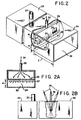
- FIG. 2 illustrates an embodiment of the invention similar to that illustrated in FIG. 1, but wherein the distribution source of the fluid layer is positioned within or adjacent to the chamber enclosure in a manner which reduces the opening size to the chamber.
- FIG. 2A illustrates a break-away cross sectional view of the portion of FIG. 2 bearing the same numerical and alphabetical identification.
- FIG. 2B is a schematically illustrated side elevation of FIG. 2, showing the feature whereby the angle of fluid flow from the fluid distribution source can be adjusted.
- FIG. 3 shows another embodiment of the invention wherein a horizontal surface or plane is protected from contact by surrounding ambient using a layer of fluid from a distribution source positioned to provide fluid flow in a direction parallel to the horizontal surface or plane.
- FIG. 3A is a schematically illustrated side elevation of FIG. 3, showing the feature whereby the angle of fluid flow from the fluid distribution source can be adjusted and whereby the spacing or distance between the fluid flow layer and the opening or surface to be protected can be adjusted.
- the present invention has broad application in materials processing wherein it is desired to reduce the amount of external fluid, gas or liquid, which travels across boundaries within which the materials processing is taking place.
- the invention is particularly useful for applications wherein it is desired to move solid material being processed across the same boundaries from which external fluids are to be excluded and for applications where optical access across the same boundaries is desired.
- the invention is useful for applications where it is desired to maintain a fluid of a given composition, temperature or other set of intensive properties on one side of an opening (process environment) to an enclosed processing area despite the presence of a fluid of a different composition, temperature or other set of intensive properties on the other side of the opening (ambient).
- FIGS. 1, 1A, and 1B One embodiment of the present invention is shown in FIGS. 1, 1A, and 1B to illustrate the general principles involved.
- a portion of an enclosed processing chamber 2 is shown having opening 4 which must be protected from entry of ambient fluid 6 present outside processing chamber 2.
- the processing chamber is filled with environment fluid 8, which differs from ambient fluid 6.
- the method of the invention is practiced by first defining a barrier plane, a rectangle in this case, 10 (shown at FIG. 1A) having a height H and a length L, across which the ambient fluid 6 is to be prevented from traveling.
- a fluid distribution source 12 having an opening through which fluid flow 14 occurs, in this case a rectangle of width W and length L, is placed on one side of the barrier rectangle 10.
- the fluid distribution source 12 is placed outside processing chamber 2, i.e., on the ambient side of the barrier rectangle 10.
- a laminar flow of fluid 14 exits the distribution source 12, in this case parallel to the barrier rectangle 10.
- the fluid flow 14 can be at an angle toward or away from the processing chamber 2 should the application require, and the desirability of the fluid flow 14 being at such an angle can be determined by sampling at any point within chamber 2 for the desired intensive properties and adjusting the fluid flow 14 direction so as to produce the preferred results.
- the width W of the fluid distribution source 12 should be at least about 0.05 times height H of opening 4.
- fluid flow 14 which defines the actual barrier 10 which is formed.
- the process environment 8, ambient 6 and fluid flow 14 may comprise any fluid composition, temperature, density or other set of intensive properties.
- Such compositions may comprise, for example, gases, liquids, plasmas, such fluids containing particulate matter, and combinations thereof.
- fluid flow 14 may mix into process environment 8, so it is preferable that the fluid comprising fluid flow 14 be inert or beneficial with regard to the process being practiced within process environment 8. Under other operating conditions, fluid flow 14 does not mix into process environment 8, so fluid which would be deleterious to the process can be used.
- the opening 4 can be of any shape, size, or orientation.
- the layer of fluid flow 14 can also be of varying shape, size or orientation irrespective of the size, shape, or orientation of opening 4. Thus, it is possible to protect only a portion of opening 4 from ambient 6 travel across barrier plane 10.
- the layer of fluid flow 14 must exhibit laminar flow characteristics.
- the performance of the layer of fluid flow 14, under a given set of conditions, can be characterized by the dimensionless Force Number which has been previously defined.
- the performance of the layer of laminar fluid flow 14 in exclusion of ambient 6 from a given volume of process environment 8 can be optimized within the following Force Number, Fr, range.
- the required range for the Force Number, Fr is between about 0.05 and about 50; the preferred Fr ranges between about 0.1 and about 10.
- the Force Number is proportional to the volumetric flow rate of fluid layer 14. Similar geometries will provide similar performance at the same Force Number.
- the performance in a new application can be estimated based on the measured performance in a previous application wherein the geometry of fluid flow 14 and the geometry of plane 10 to be protected is similar.
- the design of the fluid flow components will be a function of the degree of protection required, the cost of the environment, the cost of the fluid layer components and the judgment of the practitioner applying the method of the present invention.
- the method of the present invention is effectively used when there is a positive flow rate of fluids from within process environment 8 across barrier plane 10, when there is no environment flow exiting across barrier plane 10, or when there is a negative flow rate across barrier plane 10 (i.e., a net inflow of fluid flow layer 14 across barrier plane 10).
- the fluid layer 14 must be inert or beneficial to the environment 8, and the acceptable amount of net inflow of fluid layer 14 across barrier plane 10 is proportional to the width W of fluid layer 14 and cannot exceed the total flow of fluid flow layer 14.
- the method of the present invention is effective even when portions of barrier plane 10 which fluid flow layer 14 is to protect are blocked by physical items.
- One of the purposes of the method of the present invention is to allow physical objects which are to be processed to enter (and leave) process enclosure 2 without allowing ambient 6 to enter process enclosure 2. There is, however, reduced effectiveness of ambient 6 exclusion if the object prevents fluid flow 14 from reaching a portion of barrier plane 10 which protects a portion of opening 4. This problem can be overcome by using more than one fluid flow component so that the combination of components can reach the area of barrier plane 10 from which a fluid flow layer such as 14 is blocked off.
- FIG. 1 shows all four sides of the enclosure extended a distance E perpendicular from barrier plane 10 into and toward ambient 6. It is preferred to have distance E be greater than or equal to the width W of the fluid flow layer.
- a clear acrylic rectangular box 22, having opening 24 was purged using room temperature helium so that box 22 contained only helium at room temperature.
- the internal dimensions of box 22 were 140 mm (5.5 inches)high by 216 mm (8.5 inches) wide, by 1778 mm (70 inches) long. Because the laminar fluid distribution source 26 was mounted so that it extended downward in front of the entrance to box 22, the size of the opening 24 into box 22 was restricted to about 63.5 mm (2.5 inches) in height H by about 216 mm (8.5 inches) in length L.
- the barrier plane 28 across the opening had a total area of about 1.37 dm3 (about 21.3 square inches or about 1.48 E-1 square feet).
- the fluid distribution source 26 had a width W of about 12.7 mm (0.5 inches) and was positioned so that fluid flow from distributor 26 would be in a direction downward across opening 24.
- the 12.7 mm (0.5 inch) width of distributor 26 was about 0.20 times the distance of travel across the opening H.
- a sample point 30 was located at the bottom of the opening in the center of dimension L, so that it was immediately behind the barrier plane 28 which was on the box 22 side of the laminar fluid distribution source 26.
- the laminar fluid distribution source/device 26 was formed by constructing a box which was solid on all sides except the bottom side 25 from which the fluid 27 was to flow.
- the bottom side 25 comprised a sheet of sintered metal powder with a porosity of about 2 ⁇ m (2 microns).
- the fluid 27 used to provide the laminar layer exiting bottom 25 of distributor 26 was room temperature nitrogen.
- the nitrogen fluid was injected into an opening 32 in the top of the distributor 26.
- the size scale of any turbulence in the nitrogen fluid 27 flowing from distributor 26 was about equal to the size of porosity (about 2 ⁇ m (2 microns)) of bottom 25, much smaller than 2.5 to 12.7 mm (0.1 of the 0.5 inch) width W of distributor 26.
- the fluid flow 27 from bottom 25 of distributor 26 was expected to be laminar in nature.
- a hot wire anemometer was used to measure the velocity fluctuations as the nitrogen emerged from distributor 26. No velocity fluctuations were observed.
- the nitrogen fluid layer 27 exiting distributor 26 was laminar in nature.
- extension 34 was added to the acrylic rectangular box 22 to enhance the effect of the layer of nitrogen fluid in excluding the ambient room temperature air 36 surrounding the box 22.
- the walls of extension 34 were 140 mm (5.5 inches) high, 216 mm (8.5 inches) in width (equivalent to length L) and extended out about 58 mm (2.3 inches) past barrier plane 28 of the opening. The distance of the extension out from the barrier plane is shown as "E" in FIG. 2.
- the helium purge from the process environment to be used for a commercial process would be determined by the concentration of nitrogen in the helium environment of box 22 which could be tolerated.
- the Force Number for this example can be calculated as follows: wherein the momentum force, Fm, is given by: wherein ⁇ j is equal to the mass density of nitrogen at room temperature and pressure, about 0.00116 kg/dm3 (2.25 E-3 slugs/cubic foot). V is equal to the nitrogen fluid flow rate, about 2.945 dm3/s (1.04 E-1 cubic feet per second). Aj is the area of bottom 25 of distributor 26, about 0.274 dm2 (2.95 E-2 square feet).
- Pmax ( ⁇ ag - ⁇ heg) H where ⁇ ag is the weight density of air, 11.766 N/m3 (7.49 E-2 lb/cubic foot); ⁇ heg is the weight density of helium, 1.634 N/m3 (1.04 E-2 lb/cubic foot); and H is the height of opening 24, 0.0634 m (2.08 E-1 ft).
- Pmax equals 0.642 N/m2 (1.35 E-2 lb/ft2).
- Pmax will be the difference in pressure across the fluid layer at its source of origin.
- Ah is the area of opening 24, 1.37 dm2 (1.48 E-1 square ft).
- Fp 0.00880 N (1.99 E-3 lb) and, the value of the Force Number, fr, is about 0.65.
- a chamber of the type shown in FIGS. 2, 2A and 2B having an opening at each opposite end was equipped with a laminar fluid distribution source 26 at each opening.
- the geometry of each opening and of each distribution source was equivalent to that shown for a single opening in FIG. 2.
- the internal dimensions of the chamber 22 were about 140 mm (5.5 inches) high, 216 mm (8.5 inches) wide and 1219 mm (48 inches) long (between openings).
- Each distribution source was constructed in the manner and to about the dimensions described in Example 1.
- the ratio of width of laminar fluid layer W to the distance of travel of fluid 27 from distribution source 26 to the bottom wall of chamber 22 was about 0.20, satisfying the criteria that such ratio be at least 0.05.
- the effectiveness of the laminar fluid layer doors were enhanced by extending the chamber wall out past the openings at each end of the chamber.
- the length of extension, corresponding to "E" on FIG. 2, past each opening was 305 mm (12 inches).
- a sample point 30 was located at the bottom center of one of the openings.
- a purge gas was fed into enclosed chamber 22 at the center of the chamber, through sintered metal cylinder 37, exiting from each opening 24.
- the purge gas within enclosure 22 was room temperature nitrogen.
- the laminar fluid 27 used to create the wide laminar fluid door was also room temperature nitrogen.
- the ambient 36 surrounding chamber 22 was room temperature air.
- the weight density of nitrogen, ⁇ N2g is 11.39 N/m3 (7.25 E-2 lb per cubic foot).
- the weight density of air, ⁇ ag, is 11.77 N/m3 (7.49 E-2 lb per cubic foot).
- the height of each opening H was 0.0634 m (2.08 E-1 feet).
- Pmax equal about 0.0247 N/m2 (5.16 E-4 lb/ft2).
- the area of each opening was about 1.375 dm2 (1.48 E-1 square feet).
- Fp for each wide laminar fluid door was about 0.000339 N (7.62 E-5 lb).
- Fr is controlled by controlling the volume flow rate, V, of the fluid used to provide the fluid layer.
- V volume flow rate
- the number 38 shown on FIGS. 2, 2A and 2B represents a controlled volumetric flow rate.
- the means of control can be any means known in the art and the specific means is not part of the invention.
- a continuous furnace having two vertical openings, and having an environment of hot nitrogen was protected from contamination by ambient room temperature air surrounding the furnace, using a wide laminar fluid door comprised of air at room temperature.
- This example illustrates that the laminar fluid layer can function as an effective door even when flow of the laminar fluid itself into the process environment would be deleterious, since the laminar fluid is air at room temperature and the process environment is hot nitrogen.
- the geometry of each opening and of the distributors was similar to those described in EXAMPLE 2, except that the openings 24 were 25.4 mm (one inch) high H and 610 mm (24 inches) in length L, and the distributors 26 were 12.7 mm (0.5 inches) wide W and 610 mm (24 inches) in length.
- the furnace 22 internal dimensions were 50.8 mm (2 inches) in height by 610 mm (24 inches) in width (equivalent to L in FIG. 2) by 1016 mm (40 inches) long (between openings).
- the ratio of laminar door width W to the distance of travel from distributor bottom 25 to the bottom wall of furnace 22 was 0.50, satisfying the criteria that such ratio be at least 0.05.
- the performance of the wide laminar fluid doors was enhanced by extending the walls of the furnace out from opening 24 so that the E dimension as illustrated in FIG. 2 was about 76 mm (3 inches) at each end of furnace 22.
- a sample point (not shown on FIG. 2) was located at the bottom center of one opening 24, about 25.4 mm (one inch) back into the furnace environment from opening 24.
- the Force Number for each laminar fluid door can be calculated in a manner similar to the previous examples.
- the mass density of the room temperature air used as the laminar door fluid was 0.00120 kg/dm3 (2.33 E-3 slugs per cubic foot).
- the volume flow rate of each laminar fluid layer, V was 3.146 dm3/s (1.111 E-1 cubic feet per second).
- the area of the bottom 25 of each distributor 26, Aj was about 0.774 dm2 (8.33 E-2 square feet).
- the momentum force, Fm equaled about 0.00153 N (3.45 E-4 lb) for each jet.
- the weight density of nitrogen at about 160°C, ⁇ N2g, is about 7.886 N/m3 (5.02 E-2 lb. per cubic foot).
- the weight density of ambient air, ⁇ ag, is 11.766 N/m3 (7.49 E-2 lb. per cubic foot).
- Each opening height H was 0.0254 m (8.33 E-2 feet).
- Each opening area was about 1.55 dm2(1.67 E-1 square feet).
- Fp for each opening was about 0.00153 N (3.44 E-4 lb).
- the Force Number is about 1.0 and within the preferred range of about 0.1 to 10.0.
- a hot solder environment having no purge flow was protected from a room temperature air ambient using room temperature nitrogen laminar fluid doors over the horizontal hot solder surface.
- FIG. 3 shows the geometry of the hot solder surface 40 protected by two laminar fluid doors 56 and 60.
- the two laminar fluid doors, 56 and 60 were placed on opposite sides of solder bath 52 to prevent air above bath 52 from contacting surface 40 of bath 52 and oxidizing it.
- the solder composition was 60 weight percent tin and 40 weight percent lead.
- the temperature of the solder was 260°C.
- the total exposed area of surface 40 of solder bath 52 measured about 216 mm (8.5 inches) by about 107 mm (4.2 inches).
- the opening 62 to solder surface 40 was a rectangle, measuring about 216 mm (8.5 inches) by about 107 mm (4.2 inches), a small distance above the solder.
- the purge flow rate of the solder through opening 38 to the surrounding ambient was zero.
- the ambient around the solder bath was air.
- the laminar fluid flow, represented by vectors 42 and 44 comprised room temperature nitrogen.
- the distributors 56 and 60 for the laminar fluid were constructed as described in EXAMPLE 1.
- the 2 ⁇ m (2 micron) porous side 54 and 58 of each distributor 56 and 60, respectively, was positioned so that fluid flow vectors 42 and 44 would be parallel to surface 40 of solder bath 52.
- the room temperature nitrogen fluid represented by vectors 42 and 44 was distributed uniformly by the 2 ⁇ m (2 micron) porous sheets 54 and 58 of sintered metal so that laminar layers of room temperature nitrogen flowed across the top of solder surface 40.
- the laminar layers met at the center of the solder bath opening 62, bending upward therefrom and flowing away from solder bath surface 40.
- the laminar doors were each 25.4 mm (one inch) wide W and 216 mm (8.5 inches) long L.
- the distance of travel H of each laminar fluid door from each distributor was 53 mm (2.1 inches) so that the entire 107 mm (4.2 inch) dimension of opening 62 was protected.
- Each door protected an area 216 mm (8.5 inches) long L by 53 mm (2.1 inches) in length H.
- the ratio of laminar flow door width W to distance of travel required for door flow was about 25.4 mm (1.0 inch):53 mm (2.1 inch), or about 0.48, meeting the ratio requirement of at least 0.05.
- the effectiveness of the wide laminar flow doors was enhanced using two side shield extensions 48 and 50, one on each side of the bath adjacent to a distributor.
- the length E of each side shield was 53 mm (2.1 inches), equivalent to the distance of travel H for each laminar fluid door.
- the extensions were further enhanced by bending them at a right angle above bath 52 to form an overhang D above bath 52 which extended a distance of about 25.4 mm (one inch) over bath 52. This formed an enclosure over about 25.4 mm (one inch) of bath opening 62 along each side of bath 52 which did not have a laminar flow distributor (either 56 or 60) positioned along it.
- the height of the extension E' was about 25.4 mm (1.0 inches) above bath surface 40.
- a sample point 46 was located about 3.2 mm (0.125 inches) above the top of the solder surface in the center of opening 62.
- the oxygen concentration at sample point 46 was about 21% (equivalent to the oxygen concentration in air).
- the oxygen concentration at sample point 46 was reduced to about 0.3%.
- the nitrogen flow rate was increased to a total of about 11.3 Nm3/h (400 SCFH) from each distributor, the oxygen concentration at sample point 46 was reduced to 2.6 ppm.
- the Force Number for each distributor can be approximated in a manner similar to that used in the previous examples.
- the mass density of the nitrogen laminar fluid ⁇ j was 0.00116 kg/dm3 (2.25 E-3 slugs per cubic foot).
- the volume flow rate for each laminar fluid door, V was 1.574 dm3/s (5.56 E-2 cubic feet per second)at about 5.66 Nm3/h (200 SCFH) and 3.14 dm3/s (1.11 E-1 cubic feet per second) at about 11.3 Nm3/h (400 SCFH).
- the area of the porous portion 54 and 58 of each distributor 56 and 60, respectively, Aj was about 0.548 dm2 (5.90 E-2 square feet).
- the momentum force for each laminar flow door was about 0.000525 B (1.18 E-4 lb) at a nitrogen flow rate of about 5.66 Nm3/h (200 SCFH) and about 0.002095 N (4.71 E-4 lb) at a nitrogen flow rate of about 11.3 Nm3/h (400 SCFH).
- the pressure force, Fp is equal to the buoyance force across each laminar flow door.
- the weight density of nitrogen, ⁇ N2g is about 11.36 N/m3 (7.23 E-2 lb per cubic foot).
- the weight density of air, ⁇ ag is about 11.77 N/m3 (7.49 E-2 lb per cubic foot).
- the distance across the laminar flow layer W was about 0.0254 m (8.33 E-2 feet).
- the opening area protected by each laminar flow door, Ah was about 1.152 dm2 (1.240 E-1 square feet).
- the pressure force, Fp, across each opening was about 0.000114 (2.56 E-5 lb).
- the two laminar fluid layers of the constructed embodiment described above were operated so that the principal direction of fluid flow from each distribution device at its source of origin was located upon the same area plane.
- the two laminar fluid flow layer distributors 56 and 60 can be positioned at different spacings above opening or surface 40, such that one fluid flow layer operates over an area plane which is parallel to the area plane of the other fluid flow layer (e.g. one fluid flow layer is positioned above the other fluid flow layer) by adjusting the distance between distributor 56 or 60 and opening or surface 40 as shown in FIG. 3A.
- distributors 56 and 60 can be positioned such that the principal direction of flow from one distribution device is parallel to opening or surface 40 while the principal direction of flow from the other distribution device is at an angle to opening or surface 40, by adjusting the angle between distributor 56 or 60 and opening or surface 40 as shown in FIG. 3A, or by a combination of adjusting the distributor spacing above the opening or surface and the angle between the distributor and the opening or surface.
- each fluid flow layer distributor, 56 or 60 can comprise a different fluid, for example, a controlled volume of a first fluid 64 enters distributor device 56 while a controlled volume of a second fluid 66 enters distributor device 60.
- a fluid flow rate of 3.96 Nm3/h (140 SCFH) of argon was required for each laminar fluid door to exclude air down to a concentration of 27 ppm to 77 ppm measured at sample point 46.
- the mass density of argon, ⁇ j is about 0.00165 kg/dm3 (3.21 E-3 slugs per cubic foot).
- the volume flow rate for each laminar flow door was 1.102 Ndm3/s (3.89 E-2 standard cubic feet per second).
- the area of each fluid door, Aj was 0.548 dm2 5.9 E-2 square feet).
- Fm the momentum force for each door was 0.000366 N (8.23 E-5 lb).
- the weight density of argon, ⁇ arg, is 16.18 N/m3 (1.03 E-1 lb per cubic foot).
- the distance across the laminar flow layer, w, was 0.0254 m (8.33 E-2 feet).
- the opening area protected by each laminar flow door, Ah, was 1.152 dm2 (1.24 E-1 square feet).
- the pressure force, Fp, across each opening was about 0.001308 (2.94 E-4 lb).
- Fr is controlled by controlling the volume flow rate, V, or the fluid used to provide the fluid layer.
- the numbers 64 and 66 shown on FIG. 3 and 3A represent a controlled volumetric flow rate into fluid distributors 56 and 60, respectively.
- the means of control can be any means known in the art and the specific means is not part of the invention.
Landscapes
- Engineering & Computer Science (AREA)
- Mechanical Engineering (AREA)
- General Engineering & Computer Science (AREA)
- Physical Or Chemical Processes And Apparatus (AREA)
- Devices And Processes Conducted In The Presence Of Fluids And Solid Particles (AREA)
- Pressure Vessels And Lids Thereof (AREA)
Claims (26)
- Procédé de protection d'au moins une surface ou étendue plane (40) contre un contact ou un mélange avec un fluide extérieur, ou d'au moins une partie d'un espace fermé (2, 22) contre l'incursion de fluides extérieurs par au moins un trou (4, 24) débouchant dans ledit espace fermé, ledit procédé consistant à : faire s'écouler au moins un fluide choisi à proximité de ou directement en travers d'au moins une partie de ladite au moins une surface ou étendue plane (40) ou d'au moins un trou (4, 24) débouchant dans ledit espace fermé, sous une forme laminaire telle que la moyenne quadratique des fluctuations aléatoires de la vitesse de la couche de fluide à la source d'origine de la couche de fluide soit inférieure à environ 0,1 fois la vitesse moyenne du fluide dans sa direction d'écoulement à sa source d'origine et de façon que la moyenne quadratrique des dimensions des courants tourbillonnaires turbulents de la couche de fluide à sa source d'origine soit inférieure à 0,1 fois l'épaisseur de la couche à la source d'origine de la couche de fluide l'épaisseur ou la profondeur dudit au moins un écoulement d'un fluide choisi (14, 27, 42, 44) à la source d'origine (12, 26, 56, 60) dudit écoulement de fluide correspondant à au moins environ 0,05 fois la distance perpendiculaire à ladite au moins une partie de ladite au moins une surface ou dudit au moins un plan (40) ou perpendiculaire audit trou (4, 24) dans la direction principale d'écoulement dudit au moins un fluide choisi à la source d'origine dudit écoulement de fluide, la largeur perpendiculairement à la direction d'écoulement du fluide dudit au moins un écoulement laminaire de fluide à sa source d'origine étant au moins environ aussi grande que la largeur maximale, perpendiculairement à la direction d'écoulement du fluide, de ladite au moins une partie de ladite au moins une surface ou dudit au moins un plan ou de ladite au moins une partie dudit trou, la racine carrée du rapport de la force totale de la quantité de mouvement de la couche fluide à sa source d'origine à la force de la pression transversalement à la couche de fluide, lorsqu'il s'écoule en travers de la partie de la surface du trou, étant comprise entre environ 0,05 et environ 50 et aucune sortie n'existant dans la direction principale d'écoulement de ladite couche de fluide.
- Procédé selon la revendication 1, suivant lequel ledit au moins un écoulement de fluide choisi (14, 27, 42, 44) protège au moins environ une surface totale ou au moins une étendue plane (40) ou la totalité d'un trou (4, 24).
- Procédé selon la revendication 1 ou 2, suivant lequel ladite direction principale d'écoulement de fluide (14, 27, 42, 44) est parallèle à l'une ou l'autre de ladite au moins une surface ou étendue plane (40) ou à au moins une partie d'une étendue plane dudit au moins un trou (4, 24).
- Procédé selon la revendication 1 ou 2, suivant lequel ladite direction principale d'écoulement de fluide inscrit un angle avec l'une ou l'autre de ladite au moins une surface ou étendue plane ou avec au moins une partie d'une étendue plane dudit trou.
- Procédé selon la revendication 1 ou 2, suivant lequel il y a plus d'un écoulement laminaire de fluide (42, 44) et suivant lequel les directions principales d'écoulement desdits plus d'un écoulement de fluide à leur source d'origine sont parallèles ou sont sur la même étendue plane.
- Procédé selon la revendication 1 ou 2, suivant lequel il y a plus d'un écoulement laminaire de fluide et suivant lequel ladite direction principale d'écoulement de l'un quelconque desdits plus d'un écoulement de fluide à sa source d'origine est parallèle à au moins une partie d'au moins une surface ou étendue plane devant être protégée ou à l'un desdits au moins un trou, tandis que la direction principale d'écoulement d'un autre desdits plus d'un écoulement de fluide à sa source d'origine inscrit un angle avec au moins une autre partie d'au moins une surface ou étendue plane devant être protégée ou de l'un desdits au moins un trou.
- Procédé selon l'une quelconque des revendications précédentes, suivant lequel la racine carrée du rapport de la force totale de la quantité de mouvement de la couche de fluide à sa source d'origine à la force de la pression en travers de la couche de fluide, lorsqu'elle s'écoule transversalement à la partie de la surface du trou, est comprise entre environ 0,1 et environ 10,0.
- Procédé selon l'une quelconque des revendications précédentes, suivant lequel au moins une partie de l'une ou l'autre de ladite au moins une surface ou étendue plane ou de ladite au moins une partie de l'un quelconque desdits au moins un trou est protégée par plus d'un écoulement de fluide choisi.
- Procédé selon l'une quelconque des revendications 1 à 7, suivant lequel plus d'une surface ou étendue plane ou plus d'un trou est protégé par ledit au moins un écoulement de fluide.
- Procédé selon l'une quelconque des revendications précédentes, suivant lequel plus d'une surface ou étendue plane ou plus d'un trou est protégé par un unique écoulement de fluide.
- Procédé selon l'une quelconque des revendications précédentes, suivant lequel sensiblement tous lesdits trous débouchant dans ledit espace fermé sont protégés.
- Procédé selon l'une quelconque des revendications précédentes, suivant lequel au moins un trou débouchant dans plus d'un espace fermé est protégé par un unique écoulement de fluide.
- Procédé selon la revendication 6 ou selon la revendication 8, suivant lequel la composition d'au moins l'un desdits plus d'un écoulement de fluide est différente de la composition d'au moins un autre desdits plus d'un écoulement de fluide.
- Procédé selon l'une quelconque des revendications précédentes, suivant lequel ledit fluide choisi consiste en ledit fluide extérieur.
- Procédé selon l'une quelconque des revendications 1 à 13, suivant lequel au moins un écoulement de fluide choisi forme au moins en partie l'atmosphère régnant dans ledit espace fermé (2, 22).
- Installation de protection d'au moins une surface ou étendue plane ou d'au moins un trou débouchant dans un espace fermé contre le contact ou le mélange avec un fluide extérieur ou l'incursion de fluide extérieur, ladite installation comprenant :(a) au moins un dispositif (12, 26, 56, 60) capable de :(1) faire s'écouler une couche d'au moins un fluide à proximité de ou directement en travers d'au moins une partie de ladite au moins une surface ou étendue plane ou dudit trou (4, 24, 62) sans sortie dans la direction principale d'écoulement de ladite couche ;(2) projeter ladite couche en écoulement laminaire tel que la moyenne quadratique des fluctuations aléatoires de la vitesse de la couche à son origine soit inférieure à environ 0,1 fois la vitesse moyenne de la couche dans sa direction d'écoulement à son origine et de façon que la moyenne quadratique des dimensions des courants tourbillonnaires turbulents de ladite couche de fluide à son origine soit inférieure à 0,1 fois l'épaisseur de la couche à son origine ; et(b) un moyen de réglage de ladite couche à une profondeur ou épaisseur correspondant à au moins environ 0,05 fois la distance dans la direction principale d'écoulement entre ledit au moins un dispositif et transversalement à ladite au moins une partie de ladite au moins une surface ou étendue plane ou dudit trou ;(c) un moyen de réglage de l'écoulement de ladite couche de fluide :(1) de manière que l'écoulement soit laminaire à l'origine de la couche de la manière définie sous (a) (1) ; et(2) de façon que la racine carrée du rapport de la force totale de la quantité de mouvement de ladite couche à son origine à la force de la pression en travers de la couche lorsqu'elle s'écoule en travers de ladite au moins une partie de ladite surface ou étendue plane ou dudit trou soit comprise entre environ 0,05 et environ 50 ; et(d) un moyen de réglage de la force de la quantité de mouvement de ladite couche de fluide de façon que la racine carrée du rapport de la force totale de la quantité de mouvement de la couche de fluide à son origine à la force de la pression en travers de la couche de fluide lorsqu'il s'écoule en travers de ladite au moins une partie de ladite surface ou étendue plane ou dudit trou soit comprise entre environ 0,05 et environ 50.
- Installation selon la revendication 16, dans laquelle ledit au moins un dispositif (12, 26, 56, 60) est monté de façon que ladite direction principale d'écoulement dudit au moins un fluide choisi soit parallèle à l'un ou l'autre desdites au moins une surface ou étendue plane ou dudit trou (4, 24, 62).
- Installation selon la revendication 16, dans laquelle ledit au moins un dispositif (12, 26, 56, 60) est monté de manière que ladite direction principale d'écoulement dudit au moins un fluide choisi inscrive un angle avec l'un quelconque de ladite au moins une surface ou étendue plane ou dudit trou (4, 24, 62).
- Installation selon la revendication 16, dans laquelle on utilise plus d'un dispositif d'écoulement de fluide (56, 60) et dans laquelle au moins l'un desdits dispositifs est monté de façon que ladite direction principale d'écoulement soit parallèle à ladite au moins une surface ou étendue plane ou audit au moins un trou (62), tandis que la direction principale d'écoulement d'un autre desdits dispositifs inscrit un angle avec une autre ou avec ladite au moins une surface ou étendue plane ou avec un autre ou le même au moins un trou.
- Installation selon la revendication 16, dans laquelle on utilise plus d'un dispositif d'écoulement de fluide (56, 60) et dans laquelle les directions principales d'écoulement desdits écoulements de fluide à leur source d'origine sont parallèles ou sur la même étendue plane.
- Installation selon l'une quelconque des revendications 16 à 20, dans laquelle ledit moyen de réglage de la force de la quantité de mouvement est conçu, en ce qui concerne la force de la quantité de mouvement de chacune desdites couches d'écoulement de fluide, de manière que la racine carrée du rapport de la force totale de la quantité de mouvement de la couche de fluide à sa source d'origine à la force de la pression transversalement à la couche de fluide, lorsqu'il s'écoule en travers de la partie de l'étendue du trou, soit maintenue à ou à proximité d'un point de réglage compris entre environ 0,05 et 50.
- Installation selon la revendication 21, dans laquelle le moyen de réglage de force de la quantité de mouvement est conçu de manière à régler la force de la quantité de mouvement de chacune desdites couches d'écoulement de fluide de façon que la racine carrée du rapport de la force totale de la quantité de mouvement de la couche de fluide à sa source d'origine à la force de la pression en travers de la couche de fluide, lorsqu'il s'écoule en travers de la partie de l'étendue du trou, soit maintenue au ou à proximité d'un point de réglage allant d'environ 0,1 à 10.
- Installation selon l'une quelconque des revendications 16 à 22, dans laquelle ledit moyen de réglage de la force de la quantité de mouvement est conçu de manière à régler la force de la quantité de mouvement en réponse à des variations mesurées de la racine carrée du rapport de la force totale de la quantité de mouvement de ladite couche de fluide à sa source d'origine à la force de la pression en travers de la couche de fluide, lorsqu'il s'écoule en travers de la partie de l'étendue du trou.
- Installation selon l'une quelconque des revendications 16 à 22, dans laquelle ledit moyen de réglage de la force de la quantité de mouvement est conçu de manière à régler la force de la quantité de mouvement en réponse à un niveau de contamination mesuré sur ou à proximité de ladite surface ou étendue plane à protéger ou dans ledit espace fermé de manière à maintenir un niveau de contamination inférieur à une concentration spécifiée tout en maintenant la racine carrée du rapport de la force totale de la quantité de mouvement de la couche de fluide à sa source d'origine à la force de la pression au travers de la couche de fluide, lorsqu'il s'écoule en travers de la partie de l'étendue du trou, dans ladite plage spécifiée.
- Installation selon l'une quelconque des revendications 16 à 24, dans laquelle ledit au moins un dispositif (56, 60) dont émane ou s'écoute le fluide laminaire (42, 44) consiste en une cloison poreuse (54, 58) et dans laquelle ladite cloison poreuse a une porosité inférieure à environ 0,1 fois la profondeur ou l'épaisseur de la couche laminaire de fluide qui en émane.
- Installation selon la revendication 25, dans laquelle ladite cloison poreuse (54, 58) consiste en une feuille de poudre métallique frittée.
Applications Claiming Priority (2)
| Application Number | Priority Date | Filing Date | Title |
|---|---|---|---|
| US07/129,748 US4823680A (en) | 1987-12-07 | 1987-12-07 | Wide laminar fluid doors |
| US129748 | 1987-12-07 |
Publications (3)
| Publication Number | Publication Date |
|---|---|
| EP0319948A2 EP0319948A2 (fr) | 1989-06-14 |
| EP0319948A3 EP0319948A3 (en) | 1989-08-30 |
| EP0319948B1 true EP0319948B1 (fr) | 1994-03-02 |
Family
ID=22441419
Family Applications (1)
| Application Number | Title | Priority Date | Filing Date |
|---|---|---|---|
| EP88120428A Expired - Lifetime EP0319948B1 (fr) | 1987-12-07 | 1988-12-07 | Porte à large rideau d'écoulement laminaire de fluide |
Country Status (9)
| Country | Link |
|---|---|
| US (1) | US4823680A (fr) |
| EP (1) | EP0319948B1 (fr) |
| JP (1) | JPH01244226A (fr) |
| KR (1) | KR930004796B1 (fr) |
| BR (1) | BR8806435A (fr) |
| CA (1) | CA1281584C (fr) |
| DE (1) | DE3888115T2 (fr) |
| ES (1) | ES2049743T3 (fr) |
| MX (1) | MX165710B (fr) |
Families Citing this family (35)
| Publication number | Priority date | Publication date | Assignee | Title |
|---|---|---|---|---|
| DE3914783A1 (de) * | 1989-05-05 | 1990-11-08 | Messer Griesheim Gmbh | Vorrichtung zum verhindern des eindringens von fremdgasen durch die beschickungsoeffnung eines inertisierten reaktionsbehaelters |
| JPH0531472A (ja) * | 1990-11-17 | 1993-02-09 | Tokyo Electron Ltd | 洗浄装置 |
| US5195888A (en) * | 1991-08-19 | 1993-03-23 | Praxair Technology, Inc. | Multi-layer fluid curtains for furnace openings |
| US5210959A (en) * | 1991-08-19 | 1993-05-18 | Praxair Technology, Inc. | Ambient-free processing system |
| JP3309416B2 (ja) * | 1992-02-13 | 2002-07-29 | 松下電器産業株式会社 | 連結式クリーン空間装置 |
| US5158224A (en) * | 1992-02-24 | 1992-10-27 | Robotic Process Systems, Inc. | Soldering machine having a vertical transfer oven |
| US5617705A (en) * | 1993-09-16 | 1997-04-08 | Sanfilippo; James J. | System and method for sealing containers |
| US5816024A (en) * | 1996-05-07 | 1998-10-06 | Jescorp, Inc. | Apparatus and method for exposing product to a controlled environment |
| US6032438A (en) * | 1993-09-16 | 2000-03-07 | Sanfilippo; James J. | Apparatus and method for replacing environment within containers with a controlled environment |
| US5366409A (en) * | 1993-11-22 | 1994-11-22 | Praxair Technology, Inc. | Controlling pouring stream and receiver environment |
| US5409159A (en) * | 1994-02-28 | 1995-04-25 | L'air Liquide, Societe Anonyme Pour L'etude Et L'exploitation Des Procedes Georges Claude | Apparatus and methods for inerting solder during wave soldering operations |
| US5486383A (en) * | 1994-08-08 | 1996-01-23 | Praxair Technology, Inc. | Laminar flow shielding of fluid jet |
| US5518221A (en) | 1994-11-30 | 1996-05-21 | Air Products And Chemicals, Inc. | Method and apparatus for inert gas blanketing of a reactor or vessel used to process materials at elevated temperatures such as an induction furnace used to remelt metals for casting |
| US5682723A (en) * | 1995-08-25 | 1997-11-04 | Praxair Technology, Inc. | Turbo-laminar purging system |
| US5674309A (en) * | 1995-09-21 | 1997-10-07 | Praxair Technology, Inc. | Method and apparatus for controlled turbulent purging of open containers |
| US5795147A (en) * | 1995-11-27 | 1998-08-18 | The Boc Group, Inc. | Furnace having regulated flow rate of inerting gas |
| IL119434A (en) * | 1995-11-27 | 2000-01-31 | Boc Group Inc | Furnace |
| US5961000A (en) * | 1996-11-14 | 1999-10-05 | Sanfilippo; James J. | System and method for filling and sealing containers in controlled environments |
| US5911249A (en) * | 1997-03-13 | 1999-06-15 | Jescorp, Inc. | Gassing rail apparatus and method |
| DE19846749C2 (de) * | 1998-10-12 | 2000-10-12 | Junker Gmbh O | Aerodynamische Abdichtung von Durchlauf-Wärmebehandlungsanlagen mit Schutzgasatmosphäre |
| US6202388B1 (en) | 1998-11-06 | 2001-03-20 | Jescorp, Inc. | Controlled environment sealing apparatus and method |
| FR2788843B1 (fr) * | 1999-01-26 | 2001-04-13 | U N I R Ultra Propre Nutrition | Dispositif de protection rapprochee de produits sensibles par diffusion d'air sterile, avec des extremites d'interface protegees |
| US6270705B1 (en) | 1999-02-16 | 2001-08-07 | Praxair Technology, Inc. | Method and system for inerting polymeric film producing machines |
| FR2813817B1 (fr) * | 2000-09-13 | 2002-10-18 | Air Liquide | Dispositif de mise en forme d'objets en matiere plastique sous atmosphere inerte |
| US20030203712A1 (en) * | 2002-04-24 | 2003-10-30 | Nucci James S. | Car wash air curtain |
| US6780225B2 (en) | 2002-05-24 | 2004-08-24 | Vitronics Soltec, Inc. | Reflow oven gas management system and method |
| TWI282139B (en) * | 2002-07-01 | 2007-06-01 | Advanced Display Kabushiki Kai | Carrying vehicle, manufacturing apparatus, and carrying system |
| FR2860862B1 (fr) * | 2003-10-09 | 2006-08-04 | Air Liquide | Procede de traitement thermique d'une serie d'objets et appareil associe |
| US20070272244A1 (en) * | 2006-04-25 | 2007-11-29 | Witmer Warner H | Fluidic barrier |
| JP5127292B2 (ja) * | 2007-05-01 | 2013-01-23 | 興研株式会社 | 局所空気清浄化装置 |
| US9296600B2 (en) | 2007-07-11 | 2016-03-29 | Stokely-Van Camp, Inc. | Active sterilization zone for container filling |
| EP2522921B1 (fr) * | 2010-02-15 | 2019-03-06 | Koken Ltd. | Appareil de formation de zone locale propre |
| JP5350344B2 (ja) * | 2010-09-21 | 2013-11-27 | 新菱冷熱工業株式会社 | プッシュプル式換気システム |
| JP5543940B2 (ja) * | 2011-04-01 | 2014-07-09 | 興研株式会社 | 開放型クリーンベンチ |
| US20120297741A1 (en) * | 2011-05-25 | 2012-11-29 | John Reid | Open top work cell having a fluid barrier |
Family Cites Families (27)
| Publication number | Priority date | Publication date | Assignee | Title |
|---|---|---|---|---|
| US3053967A (en) * | 1960-04-25 | 1962-09-11 | Union Carbide Corp | Gas stream-shielded arc working |
| US3223396A (en) * | 1963-04-22 | 1965-12-14 | Hayes Inc C I | Heat treatment apparatus |
| US3332334A (en) * | 1965-08-09 | 1967-07-25 | Melzer Herman | Air curtain apparatus |
| US3575398A (en) * | 1968-11-13 | 1971-04-20 | Midland Ross Corp | Apparatus for minimizing atmosphere upset in a furnace for heat treating articles |
| US3676673A (en) * | 1969-08-18 | 1972-07-11 | Ppg Industries Inc | Apparatus for irradiation in a controlled atmosphere |
| US3618919A (en) * | 1969-11-03 | 1971-11-09 | Btu Eng Corp | Adjustable heat and gas barrier |
| GB1332928A (en) * | 1970-11-20 | 1973-10-10 | Belousov A A | Controlled-atmosphere furnace with gas seal |
| DE2305923A1 (de) * | 1972-02-11 | 1973-08-16 | Marc Fordsmand | Verfahren und vorrichtung zur abschirmung von tueroeffnungen |
| US3807052A (en) * | 1972-06-26 | 1974-04-30 | Union Carbide Corp | Apparatus for irradiation of a moving product in an inert atmosphere |
| US4023398A (en) * | 1975-03-03 | 1977-05-17 | John Barry French | Apparatus for analyzing trace components |
| US3936950A (en) * | 1974-04-16 | 1976-02-10 | Union Carbide Corporation | Method of inerting the atmosphere above a moving product |
| SE400632C (sv) * | 1975-11-06 | 1984-07-09 | Jansson Bror Ingvar Erling | Anordning for att forhindra stromning av luft genom en oppning mellan tva utrymmen |
| JPS5288850A (en) * | 1976-01-20 | 1977-07-25 | Nippon Air Curtain Kk | Variable inclined air curtain unit |
| JPS5338511U (fr) * | 1976-09-04 | 1978-04-04 | ||
| US4135098A (en) * | 1976-11-05 | 1979-01-16 | Union Carbide Corporation | Method and apparatus for curing coating materials |
| JPS542243A (en) * | 1977-06-09 | 1979-01-09 | Asahi Glass Co Ltd | Ultrasonic wave soldering apparatus |
| AT362809B (de) * | 1978-12-11 | 1981-06-25 | Messer Griesheim Austria Gesse | Verwendung eines brenngas-stickstoff-gemisches zur speisung eines der eingangstuer eines gluehofens zur waermebehandlung von werkstuecken zugeordneten brennerrohres |
| US4223450A (en) * | 1979-07-05 | 1980-09-23 | Airco, Inc. | Methods and apparatus for controlling gas flows |
| US4315456A (en) * | 1979-12-05 | 1982-02-16 | Sanko Air Plant, Ltd. | Air-curtaining apparatus for fire protection |
| US4298341A (en) * | 1980-03-21 | 1981-11-03 | Nowack William C | Industrial oven having air recirculating means for minimizing heat loss |
| DE3106790C2 (de) * | 1981-02-24 | 1982-12-23 | Oschatz Gmbh, 4300 Essen | Einrichtung zum Abschirmen eines Offenbereiches zwischen einem Industrieofen, insbesondere Konverter, und einem Ofenkamin mittels eines Sperrgasvorhanges |
| US4448616A (en) * | 1981-07-20 | 1984-05-15 | Union Carbide Corporation | Process for reducing backmixing |
| GB2139741B (en) * | 1983-05-04 | 1988-06-08 | Air Prod & Chem | Method of operating heat treatment furnace |
| US4491610A (en) * | 1983-10-21 | 1985-01-01 | Ashland Oil, Inc. | Gas curing chamber for flat substrates |
| US4610391A (en) * | 1984-12-18 | 1986-09-09 | Union Carbide Corporation | Process for wave soldering |
| US4696226A (en) * | 1986-08-28 | 1987-09-29 | Witmer Warner H | Fluid barrier curtain system |
| JPH05267333A (ja) * | 1992-03-23 | 1993-10-15 | Nec Corp | Mos型電界効果トランジスタの製造方法 |
-
1987
- 1987-12-07 US US07/129,748 patent/US4823680A/en not_active Expired - Lifetime
-
1988
- 1988-12-07 ES ES88120428T patent/ES2049743T3/es not_active Expired - Lifetime
- 1988-12-07 DE DE3888115T patent/DE3888115T2/de not_active Expired - Fee Related
- 1988-12-07 JP JP63307957A patent/JPH01244226A/ja active Pending
- 1988-12-07 BR BR888806435A patent/BR8806435A/pt not_active IP Right Cessation
- 1988-12-07 KR KR1019880016358A patent/KR930004796B1/ko not_active Expired - Fee Related
- 1988-12-07 CA CA000585192A patent/CA1281584C/fr not_active Expired - Lifetime
- 1988-12-07 MX MX014072A patent/MX165710B/es unknown
- 1988-12-07 EP EP88120428A patent/EP0319948B1/fr not_active Expired - Lifetime
Also Published As
| Publication number | Publication date |
|---|---|
| ES2049743T3 (es) | 1994-05-01 |
| EP0319948A2 (fr) | 1989-06-14 |
| KR890010522A (ko) | 1989-08-09 |
| MX165710B (es) | 1992-12-01 |
| BR8806435A (pt) | 1989-08-22 |
| US4823680A (en) | 1989-04-25 |
| JPH01244226A (ja) | 1989-09-28 |
| CA1281584C (fr) | 1991-03-19 |
| KR930004796B1 (ko) | 1993-06-08 |
| DE3888115D1 (de) | 1994-04-07 |
| DE3888115T2 (de) | 1994-08-04 |
| EP0319948A3 (en) | 1989-08-30 |
Similar Documents
| Publication | Publication Date | Title |
|---|---|---|
| US4823680A (en) | Wide laminar fluid doors | |
| KR100310756B1 (ko) | 웨이브 솔더링 방법 및 장치 | |
| JP3651805B2 (ja) | クリーンエアカーテンによる領域の動的分離方法 | |
| EP3611277B1 (fr) | Procédé pour la production d'un lingot de métal | |
| CA2071400A1 (fr) | Procede de preparation de granules | |
| EP0528405B1 (fr) | Système de traitement sans air ambiant | |
| US4860643A (en) | Ventilated clean room work station with aerodynamic exhaust baffle | |
| US3994210A (en) | Jet fume control systems | |
| CA2142893A1 (fr) | Methode de charge de solides dans un metal en fusion | |
| KR0134360B1 (ko) | 개구부 주위 및 개구부내의 영역에 선택된 분위기를 제공하기 위한 방법 및 장치와 그 장치에 사용되는 확산기 및 밀봉체 | |
| US4692180A (en) | Apparatus and method for depositing a metal oxide coating on a glass substrate | |
| US4920998A (en) | Method and apparatus for controlling flow bias in a multiple zone process | |
| FI97900B (fi) | Teräsnauhan meniskipinnoittaminen | |
| JPS60159162A (ja) | 金属の噴霧沈着法 | |
| KR100208703B1 (ko) | 반도체 크린룸 시스템 | |
| EP0337008A2 (fr) | Procédé et dispositif pour commander des mouvements croisés de fluides dans un procédé à zones multiples | |
| SE462704B (sv) | Foerfarande vid atomisering av vaetskor och anordning foer genomfoerande av foerfarandet | |
| EP0654314A1 (fr) | Régulation de l'environnement du jet de coulée et du récipient | |
| CN1236881C (zh) | 熔融的金属膜均匀化的方法和设备 | |
| US3930075A (en) | Method for controlling splashing resulting from the use of gas knives | |
| JPS5725261A (en) | Manufacture of thin plate | |
| EP0411853A1 (fr) | Procédé et appareil de revêtement en continu par immersion de bandes d'acier | |
| Hirosawa | Vacuum Degassing of Molten Aluminum | |
| KR101439640B1 (ko) | 스나우트의 기체유동 조절장치 | |
| KR101568472B1 (ko) | 스나우트의 기체유동 조절장치 및 이를 이용한 도금강판 제조장치 |
Legal Events
| Date | Code | Title | Description |
|---|---|---|---|
| PUAI | Public reference made under article 153(3) epc to a published international application that has entered the european phase |
Free format text: ORIGINAL CODE: 0009012 |
|
| AK | Designated contracting states |
Kind code of ref document: A2 Designated state(s): AT BE CH DE ES FR GB GR IT LI LU NL SE |
|
| PUAL | Search report despatched |
Free format text: ORIGINAL CODE: 0009013 |
|
| AK | Designated contracting states |
Kind code of ref document: A3 Designated state(s): AT BE CH DE ES FR GB GR IT LI LU NL SE |
|
| 17P | Request for examination filed |
Effective date: 19890908 |
|
| 17Q | First examination report despatched |
Effective date: 19910314 |
|
| RAP1 | Party data changed (applicant data changed or rights of an application transferred) |
Owner name: PRAXAIR TECHNOLOGY, INC. |
|
| RBV | Designated contracting states (corrected) |
Designated state(s): BE DE ES FR GB IT LU NL |
|
| ITF | It: translation for a ep patent filed | ||
| GRAA | (expected) grant |
Free format text: ORIGINAL CODE: 0009210 |
|
| AK | Designated contracting states |
Kind code of ref document: B1 Designated state(s): BE DE ES FR GB IT LU NL |
|
| REF | Corresponds to: |
Ref document number: 3888115 Country of ref document: DE Date of ref document: 19940407 |
|
| REG | Reference to a national code |
Ref country code: ES Ref legal event code: FG2A Ref document number: 2049743 Country of ref document: ES Kind code of ref document: T3 |
|
| ET | Fr: translation filed | ||
| PLBE | No opposition filed within time limit |
Free format text: ORIGINAL CODE: 0009261 |
|
| STAA | Information on the status of an ep patent application or granted ep patent |
Free format text: STATUS: NO OPPOSITION FILED WITHIN TIME LIMIT |
|
| 26N | No opposition filed | ||
| PGFP | Annual fee paid to national office [announced via postgrant information from national office to epo] |
Ref country code: GB Payment date: 19951124 Year of fee payment: 8 |
|
| PGFP | Annual fee paid to national office [announced via postgrant information from national office to epo] |
Ref country code: LU Payment date: 19951201 Year of fee payment: 8 |
|
| PG25 | Lapsed in a contracting state [announced via postgrant information from national office to epo] |
Ref country code: LU Free format text: LAPSE BECAUSE OF NON-PAYMENT OF DUE FEES Effective date: 19961207 Ref country code: GB Effective date: 19961207 |
|
| GBPC | Gb: european patent ceased through non-payment of renewal fee |
Effective date: 19961207 |
|
| PGFP | Annual fee paid to national office [announced via postgrant information from national office to epo] |
Ref country code: FR Payment date: 20021119 Year of fee payment: 15 |
|
| PGFP | Annual fee paid to national office [announced via postgrant information from national office to epo] |
Ref country code: NL Payment date: 20021121 Year of fee payment: 15 |
|
| PGFP | Annual fee paid to national office [announced via postgrant information from national office to epo] |
Ref country code: BE Payment date: 20021218 Year of fee payment: 15 |
|
| PGFP | Annual fee paid to national office [announced via postgrant information from national office to epo] |
Ref country code: DE Payment date: 20021230 Year of fee payment: 15 |
|
| PGFP | Annual fee paid to national office [announced via postgrant information from national office to epo] |
Ref country code: ES Payment date: 20030109 Year of fee payment: 15 |
|
| PG25 | Lapsed in a contracting state [announced via postgrant information from national office to epo] |
Ref country code: ES Free format text: LAPSE BECAUSE OF NON-PAYMENT OF DUE FEES Effective date: 20031209 |
|
| PG25 | Lapsed in a contracting state [announced via postgrant information from national office to epo] |
Ref country code: BE Free format text: LAPSE BECAUSE OF NON-PAYMENT OF DUE FEES Effective date: 20031231 |
|
| BERE | Be: lapsed |
Owner name: *PRAXAIR TECHNOLOGY INC. Effective date: 20031231 |
|
| PG25 | Lapsed in a contracting state [announced via postgrant information from national office to epo] |
Ref country code: NL Free format text: LAPSE BECAUSE OF NON-PAYMENT OF DUE FEES Effective date: 20040701 Ref country code: DE Free format text: LAPSE BECAUSE OF NON-PAYMENT OF DUE FEES Effective date: 20040701 |
|
| PG25 | Lapsed in a contracting state [announced via postgrant information from national office to epo] |
Ref country code: FR Free format text: LAPSE BECAUSE OF NON-PAYMENT OF DUE FEES Effective date: 20040831 |
|
| NLV4 | Nl: lapsed or anulled due to non-payment of the annual fee |
Effective date: 20040701 |
|
| REG | Reference to a national code |
Ref country code: FR Ref legal event code: ST |
|
| REG | Reference to a national code |
Ref country code: ES Ref legal event code: FD2A Effective date: 20031209 |
|
| PG25 | Lapsed in a contracting state [announced via postgrant information from national office to epo] |
Ref country code: IT Free format text: LAPSE BECAUSE OF NON-PAYMENT OF DUE FEES;WARNING: LAPSES OF ITALIAN PATENTS WITH EFFECTIVE DATE BEFORE 2007 MAY HAVE OCCURRED AT ANY TIME BEFORE 2007. THE CORRECT EFFECTIVE DATE MAY BE DIFFERENT FROM THE ONE RECORDED. Effective date: 20051207 |