EP0320029A1 - Stossdämpfer für den Streichbaum einer Webmaschine - Google Patents
Stossdämpfer für den Streichbaum einer Webmaschine Download PDFInfo
- Publication number
- EP0320029A1 EP0320029A1 EP88202522A EP88202522A EP0320029A1 EP 0320029 A1 EP0320029 A1 EP 0320029A1 EP 88202522 A EP88202522 A EP 88202522A EP 88202522 A EP88202522 A EP 88202522A EP 0320029 A1 EP0320029 A1 EP 0320029A1
- Authority
- EP
- European Patent Office
- Prior art keywords
- core
- damping device
- solenoid
- damper
- weaving machine
- Prior art date
- Legal status (The legal status is an assumption and is not a legal conclusion. Google has not performed a legal analysis and makes no representation as to the accuracy of the status listed.)
- Ceased
Links
- 238000013016 damping Methods 0.000 title claims abstract description 40
- 238000009941 weaving Methods 0.000 title claims abstract description 23
- 230000000694 effects Effects 0.000 claims description 17
- XEEYBQQBJWHFJM-UHFFFAOYSA-N Iron Chemical compound [Fe] XEEYBQQBJWHFJM-UHFFFAOYSA-N 0.000 claims description 8
- 229910052742 iron Inorganic materials 0.000 claims description 4
- 238000006073 displacement reaction Methods 0.000 claims 1
- 239000004744 fabric Substances 0.000 description 4
- 230000004907 flux Effects 0.000 description 4
- 238000010276 construction Methods 0.000 description 3
- 235000014676 Phragmites communis Nutrition 0.000 description 2
- 239000004020 conductor Substances 0.000 description 2
- 230000005291 magnetic effect Effects 0.000 description 2
- 230000010355 oscillation Effects 0.000 description 2
- 230000002411 adverse Effects 0.000 description 1
- 238000010009 beating Methods 0.000 description 1
- 238000013017 mechanical damping Methods 0.000 description 1
- 230000010358 mechanical oscillation Effects 0.000 description 1
- 238000000034 method Methods 0.000 description 1
Images

Classifications
-
- D—TEXTILES; PAPER
- D03—WEAVING
- D03D—WOVEN FABRICS; METHODS OF WEAVING; LOOMS
- D03D49/00—Details or constructional features not specially adapted for looms of a particular type
- D03D49/04—Control of the tension in warp or cloth
- D03D49/12—Controlling warp tension by means other than let-off mechanisms
- D03D49/14—Compensating for tension differences during shedding
-
- D—TEXTILES; PAPER
- D03—WEAVING
- D03D—WOVEN FABRICS; METHODS OF WEAVING; LOOMS
- D03D49/00—Details or constructional features not specially adapted for looms of a particular type
- D03D49/04—Control of the tension in warp or cloth
- D03D49/22—Back rests; Lease rods; Brest beams
-
- F—MECHANICAL ENGINEERING; LIGHTING; HEATING; WEAPONS; BLASTING
- F16—ENGINEERING ELEMENTS AND UNITS; GENERAL MEASURES FOR PRODUCING AND MAINTAINING EFFECTIVE FUNCTIONING OF MACHINES OR INSTALLATIONS; THERMAL INSULATION IN GENERAL
- F16F—SPRINGS; SHOCK-ABSORBERS; MEANS FOR DAMPING VIBRATION
- F16F15/00—Suppression of vibrations in systems; Means or arrangements for avoiding or reducing out-of-balance forces, e.g. due to motion
- F16F15/02—Suppression of vibrations of non-rotating, e.g. reciprocating systems; Suppression of vibrations of rotating systems by use of members not moving with the rotating systems
- F16F15/03—Suppression of vibrations of non-rotating, e.g. reciprocating systems; Suppression of vibrations of rotating systems by use of members not moving with the rotating systems using magnetic or electromagnetic means
-
- G—PHYSICS
- G05—CONTROLLING; REGULATING
- G05D—SYSTEMS FOR CONTROLLING OR REGULATING NON-ELECTRIC VARIABLES
- G05D19/00—Control of mechanical oscillations, e.g. of amplitude, of frequency, of phase
- G05D19/02—Control of mechanical oscillations, e.g. of amplitude, of frequency, of phase characterised by the use of electric means
Definitions
- This invention concerns a damping device for the backrest roller of a weaving machine.
- the warp threads from the warp beam are bent over a backrest roller and guided toward the weaving frames.
- a backrest roller is suspended such that it is mobile, and provided with an elastic mechanism, so that it can be forced in one direction such that the warp threads are kept under tension. Due to the opening and closing of the shed, movements take place in the warp during weaving, resulting in an oscillating movement of the backrest roller.
- it is equipped with a damper.
- conventional oil dampers are used for this purpose, consisting of an oil-filled cylinder and a piston mounted inside the cylinder, provided with passages so that the oil can flow from one side of the piston to the other.
- dampers also have the disadvantage that they lose their damping effect to a certain extent as soon as they heat up, partly because the oil then becomes less viscous and can more easily flow from one damper chamber to the other and vice-versa.
- the present invention has as its aim to provide a damping device for the backrest roller of a weaving machine whereby the above-mentioned disadvantages are systematically avoided.
- the damping effect of the damping device according to the invention can be adjusted electrically and/or electronically, thereby giving it the advantage that it can be automatically and rapidly adjusted without any mechanical intervention.
- Such adjustment enables the damping effect on the backrest roller to be modified during weaving. With a suitable adjustment, starting marks during weaving machine startup can be simply prevented, or at least kept to a minimum.
- the damping device consists essentially: of a damper formed by a first core provided with a solenoid and a second core, whereby these cores can make to-and-fro movements relative to one another, and whereby each of them is connected to one of the opposite attachment points of the damper; and means that determine the electric current in the solenoid.
- the friction in the damper can be kept very low with respect to the friction occurring in the known oil dampers, with the advantage that little or no wear occurs.
- the second core of the damper consists of a permanent magnet, while the means of determining the electric current in the solenoid consists of an electrical load, preferably adjustable.
- This embodiment offers the specific advantage that the oscillation energy can be converted into heat which can be discharged outside the damper, more specifically to the electrical load. The damper therefore does not heat up.
- the second core consists of a soft iron body, while the means to determine the electric current in the solenoid consist of a current generator, preferably adjustable.
- Fig. 1 shows a conventional oil damper 1, consisting of a cylindrical housing 2, to which a first attachment point 3 is secured, and a piston 4 which can move within the oil damper 1 and which is connected to the second attachment point 5.
- the piston 4 is provided with a number of passages 6 for the oil 7 in the cylinder 2, such that this oil can flow between the chambers 8 and 9 during the to-and-fro movement of the piston 4.
- Fig. 2 shows a weaving machine in which the damping device 10 according to the invention is illustrated.
- the most important components of the weaving machine in this embodiment are, as is known, the warp beam 11, the warp threads or warp 12, a mobile backrest roller 13, an optional fixed backrest roller 14, a warp stop motion 15, the weaving harnesses 16, the reed 17, the cloth 18, and the cloth beam 19.
- the mobile backrest roller 13 is suspended close to its extremities in supports 21, which can revolve around a fixed point 20; said supports can be forced into a given position by elastic means 22, such as a spring.
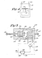
- the damping device 10 as shown in fig. 3 consists essentially of firstly a damper 23 comprising a first core 24 provided with a solenoid 25, and a second core 26, whereby the first and second cores are mobile with respect to one another, and each of them is connected to the opposite attachment point 27 or 28 of the damper 23, and secondly of means 29 to determine the electric current I in the solenoid.
- one or more dampers 23 are located parallel to the elastic means 22, whereby they are therefore connected firstly to the rotating supports 21, and secondly to the frame 30 of the weaving machine.
- the core 24 that carries the solenoid 25 is preferably fixed-mounted, in other words the attachment point 27 is connected to the frame 30 of the weaving machine, while the attachment point 28 that is connected to the second core 26 is coupled to the rotating supports 21.
- the solenoid 25 is not subject to the oscillation of the backrest roller during the operation of the weaving machine, so that the likelihood of mechanical damage to the solenoid 25 is limited.
- the second core 26 is generally smaller than the first core 24, for reasons of construction, it is also dynamically more advantageous to couple the second core, rather than the first core, to the mobile backrest roller.
- the first core 24 consists of a magnetically conducting material, such as soft iron, while the second core 26 consists essentially of a permanent magnet.
- the means 29 that determine the electric current I in the solenoid 25 consists essentially of an electrical load 31, preferably adjustable, such as for example, an adjustable electrical resistor or an adjustable electronic load.
- the operation of the device as shown in fig. 3 can be deduced simply from the figure, and consists in the generation of a variable flux 32 in the first core 24 as a result of the to-and-fro movement movement of the second core 26, resulting in the generation of a voltage in the solenoid 25, which, owing to the presence of the electrical load 31, creates the above-mentioned current I.
- This causes the power in the electrical load 31 to be dispersed, so that the mechanical oscillation energy is converted into heat, and a mechanical damping effect is created in the damper 23.
- the above-mentioned means 29 can include a control unit 33, whereby the quantity of the electrical load 31 can be adjusted by means of set values 34.
- the setting may or may not be modified automatically during the weaving process.
- the quantity of damping has to be adjusted to suit the type of warp threads. It should be noted that with highly elastic threads the damping effect should preferably be set high, and with threads having low elasticity, the damping effect should preferably be set low. It is in fact known that if a high damping effect is selected with low elasticity threads, thread breakages will occur frequently.
- the adjustment should also preferably be set to suit the movements of the backrest roller 13, for example, by using a detector 35 that operates with the backrest roller 13, or on a swivel support 21 of the backrest roller 13, and that transmits a signal 36 as a function of the movement of the backrest roller 13.
- the oscillating movement of the backrest roller 13 occurs as a result of the movement of the warp threads 12, which is in turn the result of the opening and closing of the shed 37.
- the amplitude of the movement of the backrest roller 13 can be measured with the detector 35.
- a possible adjustment, which can be performed with the control unit 33 in this case, consists in modifying the quantity of the electrical load 31 in order to determine experimentally which setting ensures the optimum damping effect, in other words the least amplitude of the movement of the backrest roller 13.
- the startup or the start signal 38 of the weaving machine can also be taken into consideration, in order to modify the damping effect of the damper 23 such that starting marks are prevented, or at least kept to a minimum.
- the damping effect on the backrest roller 13 can be set as high as possible before startup, so that unwanted movement of the backrest roller 13 during startup can be eliminated as far as possible.
- the backrest roller 13 can be kept practically immobile, so that when the shed is formed the tension in the warp 12 increases, and the cloth line or fell line 39 is driven backward, so that the adverse effect of the insufficient beating up power of the sley or the reed 17 at startup is compensated. In this way, starting marks in the cloth 18 are prevented.
- the adjustable electrical load 31 can consist of a resistor 40, with a mobile centre tap 41 which is connected to one of the side connections 42, so that by altering the position of the centre tap 41 it is possible to adjust the resistance at the clamps 43 and 44.
- the electrical load 31 can also consist of an electronic load, in other words a load consisting of electronic components. This type of load presents the advantage that it can be adjusted more quickly.
- Fig. 5 shows a variant of the invention in which both the first and second cores consists of a magnetically conducting material, such as soft iron, and in which the means 29 to determine the electric current I in the solenoid consist of a current generator 45 to which the solenoid 25 is connected.
- a magnetically conducting material such as soft iron
- this damper 23 is as follows. When a current I is routed through the solenoid 25, a flux 32 is generated. Because of the to-and-fro movement of the second core 26, the flux 32 fluctuates. The magnetic field generated by the fluctuations of the flux 32 excites eddy currents in this core 26, so that the mechanical energy is converted into heat, which also creates a damping effect.
- the current generator 45 should preferably be adjustable, so that the damping effect can be adjusted. Again, control can be exercised by means of the above-mentioned control unit 33.
- both cores are preferably as shown in figs. 3 and 5; in other words, the first core 24 consists of a cylindrical housing 46, closed by a radial wall 47 provided with an inward-orientated axial part 48 around which the solenoid 25 is wound, and the second core 26 consists of a cylindrical body located in line with said part 48.
- the outer wall 49 of the cylindrical body of the second core 26 can slide in the inner wall 50 of the cylindrical housing 41, so that said cylindrical body slides.
Landscapes
- Engineering & Computer Science (AREA)
- Physics & Mathematics (AREA)
- Textile Engineering (AREA)
- General Engineering & Computer Science (AREA)
- Electromagnetism (AREA)
- Acoustics & Sound (AREA)
- Aviation & Aerospace Engineering (AREA)
- Mechanical Engineering (AREA)
- General Physics & Mathematics (AREA)
- Automation & Control Theory (AREA)
- Looms (AREA)
Applications Claiming Priority (2)
| Application Number | Priority Date | Filing Date | Title |
|---|---|---|---|
| BE8701387A BE1001267A4 (nl) | 1987-12-04 | 1987-12-04 | Dempinrichting voor de sleep van een weefmachine. |
| BE8701387 | 1987-12-04 |
Publications (1)
| Publication Number | Publication Date |
|---|---|
| EP0320029A1 true EP0320029A1 (de) | 1989-06-14 |
Family
ID=3883004
Family Applications (1)
| Application Number | Title | Priority Date | Filing Date |
|---|---|---|---|
| EP88202522A Ceased EP0320029A1 (de) | 1987-12-04 | 1988-11-11 | Stossdämpfer für den Streichbaum einer Webmaschine |
Country Status (2)
| Country | Link |
|---|---|
| EP (1) | EP0320029A1 (de) |
| BE (1) | BE1001267A4 (de) |
Cited By (2)
| Publication number | Priority date | Publication date | Assignee | Title |
|---|---|---|---|---|
| CN111235727A (zh) * | 2020-03-19 | 2020-06-05 | 陈李兰 | 一种用于新材料制备的喷气织机张力调节装置 |
| US11181165B2 (en) * | 2013-09-15 | 2021-11-23 | Valmont Industries, Inc. | Vibration mitigation device |
Citations (7)
| Publication number | Priority date | Publication date | Assignee | Title |
|---|---|---|---|---|
| CH344689A (de) * | 1956-04-13 | 1960-02-15 | Sulzer Ag | Webmaschine |
| US2973969A (en) * | 1955-05-11 | 1961-03-07 | Earle S Thall | Electrical shock absorbing system |
| US3072154A (en) * | 1958-10-22 | 1963-01-08 | Zellweger Uster Ag | Method and device for electrically controlling the warp tension in looms for weaving |
| US3174587A (en) * | 1964-03-12 | 1965-03-23 | Walton Marvin | Adjustable shock absorber |
| FR2339762A1 (fr) * | 1976-02-02 | 1977-08-26 | Maschf Augsburg Nuernberg Ag | Installation comportant un corps tournant a grande vitesse |
| FR2567925A1 (fr) * | 1984-07-19 | 1986-01-24 | Alsacienne Constr Mat Tex | Dispositif pour ensemble porte-fils apte a fonctionner comme amortisseur en phases de marche du metier et en moyen de blocage en phases d'arret du metier |
| DE3543492A1 (de) * | 1985-12-09 | 1987-06-11 | Harald Teinzer | Elektromagnetische stossdaempfung, verfahren und vorrichtung |
-
1987
- 1987-12-04 BE BE8701387A patent/BE1001267A4/nl not_active IP Right Cessation
-
1988
- 1988-11-11 EP EP88202522A patent/EP0320029A1/de not_active Ceased
Patent Citations (7)
| Publication number | Priority date | Publication date | Assignee | Title |
|---|---|---|---|---|
| US2973969A (en) * | 1955-05-11 | 1961-03-07 | Earle S Thall | Electrical shock absorbing system |
| CH344689A (de) * | 1956-04-13 | 1960-02-15 | Sulzer Ag | Webmaschine |
| US3072154A (en) * | 1958-10-22 | 1963-01-08 | Zellweger Uster Ag | Method and device for electrically controlling the warp tension in looms for weaving |
| US3174587A (en) * | 1964-03-12 | 1965-03-23 | Walton Marvin | Adjustable shock absorber |
| FR2339762A1 (fr) * | 1976-02-02 | 1977-08-26 | Maschf Augsburg Nuernberg Ag | Installation comportant un corps tournant a grande vitesse |
| FR2567925A1 (fr) * | 1984-07-19 | 1986-01-24 | Alsacienne Constr Mat Tex | Dispositif pour ensemble porte-fils apte a fonctionner comme amortisseur en phases de marche du metier et en moyen de blocage en phases d'arret du metier |
| DE3543492A1 (de) * | 1985-12-09 | 1987-06-11 | Harald Teinzer | Elektromagnetische stossdaempfung, verfahren und vorrichtung |
Cited By (3)
| Publication number | Priority date | Publication date | Assignee | Title |
|---|---|---|---|---|
| US11181165B2 (en) * | 2013-09-15 | 2021-11-23 | Valmont Industries, Inc. | Vibration mitigation device |
| US11821487B2 (en) | 2013-09-15 | 2023-11-21 | Valmont Industries, Inc. | Vibration mitigation device |
| CN111235727A (zh) * | 2020-03-19 | 2020-06-05 | 陈李兰 | 一种用于新材料制备的喷气织机张力调节装置 |
Also Published As
| Publication number | Publication date |
|---|---|
| BE1001267A4 (nl) | 1989-09-05 |
Similar Documents
| Publication | Publication Date | Title |
|---|---|---|
| US5553641A (en) | Positive modulated braking of the thread for weft feeders | |
| KR101270799B1 (ko) | 드럼식 세탁기 | |
| US3233133A (en) | Alternating current generator | |
| KR101516470B1 (ko) | 세탁기 | |
| CZ20012227A3 (cs) | Vodič nití k příčnému přívodu nitě k rotující předlohové cívce | |
| US2112264A (en) | Electrodynamic apparatus | |
| EA023486B1 (ru) | Бытовой прибор, имеющий привод вращения с управляемым распределением магнитного поля в двигателе привода | |
| US3053474A (en) | Tension control device | |
| US2845235A (en) | Electromagnetic wire tension device | |
| US2698590A (en) | Thread tension regulator for sewing machines | |
| US3242365A (en) | Generator voltage control | |
| US2685838A (en) | Electromagnetic pump | |
| US3351296A (en) | Electromagnetic thread-tension control assembly | |
| EP0066128A1 (de) | Vorrichtung zur Herstellung von Garnkörpern | |
| US2450470A (en) | Electronically controlled motordriven loom letoff | |
| US2539295A (en) | Warp letoff mechanism | |
| BE1001267A4 (nl) | Dempinrichting voor de sleep van een weefmachine. | |
| US1966214A (en) | Control system | |
| CN209456681U (zh) | 一种缝纫机上的面线张力稳定装置 | |
| KR102510337B1 (ko) | 세탁기 | |
| US3446043A (en) | Speed control for a laundry machine | |
| US2461493A (en) | Loom fork filling motion | |
| US3221235A (en) | Oscillator controlled by centrifugal switch for regulating motor speed | |
| US2045058A (en) | Grinding mill | |
| US2518158A (en) | Electrical let-off |
Legal Events
| Date | Code | Title | Description |
|---|---|---|---|
| PUAI | Public reference made under article 153(3) epc to a published international application that has entered the european phase |
Free format text: ORIGINAL CODE: 0009012 |
|
| AK | Designated contracting states |
Kind code of ref document: A1 Designated state(s): CH DE FR IT LI |
|
| 17P | Request for examination filed |
Effective date: 19890628 |
|
| 17Q | First examination report despatched |
Effective date: 19900919 |
|
| STAA | Information on the status of an ep patent application or granted ep patent |
Free format text: STATUS: THE APPLICATION HAS BEEN REFUSED |
|
| 18R | Application refused |
Effective date: 19910819 |