EP0320163B1 - Système de commande de position - Google Patents
Système de commande de position Download PDFInfo
- Publication number
- EP0320163B1 EP0320163B1 EP88311296A EP88311296A EP0320163B1 EP 0320163 B1 EP0320163 B1 EP 0320163B1 EP 88311296 A EP88311296 A EP 88311296A EP 88311296 A EP88311296 A EP 88311296A EP 0320163 B1 EP0320163 B1 EP 0320163B1
- Authority
- EP
- European Patent Office
- Prior art keywords
- signal
- stepping motor
- generating
- current
- control system
- Prior art date
- Legal status (The legal status is an assumption and is not a legal conclusion. Google has not performed a legal analysis and makes no representation as to the accuracy of the status listed.)
- Expired - Lifetime
Links
Images


Classifications
-
- G—PHYSICS
- G05—CONTROLLING; REGULATING
- G05B—CONTROL OR REGULATING SYSTEMS IN GENERAL; FUNCTIONAL ELEMENTS OF SUCH SYSTEMS; MONITORING OR TESTING ARRANGEMENTS FOR SUCH SYSTEMS OR ELEMENTS
- G05B19/00—Program-control systems
- G05B19/02—Program-control systems electric
- G05B19/18—Numerical control [NC], i.e. automatically operating machines, in particular machine tools, e.g. in a manufacturing environment, so as to execute positioning, movement or co-ordinated operations by means of program data in numerical form
- G05B19/19—Numerical control [NC], i.e. automatically operating machines, in particular machine tools, e.g. in a manufacturing environment, so as to execute positioning, movement or co-ordinated operations by means of program data in numerical form characterised by positioning or contouring control systems, e.g. to control position from one programmed point to another or to control movement along a programmed continuous path
- G05B19/39—Numerical control [NC], i.e. automatically operating machines, in particular machine tools, e.g. in a manufacturing environment, so as to execute positioning, movement or co-ordinated operations by means of program data in numerical form characterised by positioning or contouring control systems, e.g. to control position from one programmed point to another or to control movement along a programmed continuous path using a combination of the means covered by at least two of the preceding groups G05B19/21, G05B19/27 and G05B19/33
-
- G—PHYSICS
- G05—CONTROLLING; REGULATING
- G05D—SYSTEMS FOR CONTROLLING OR REGULATING NON-ELECTRIC VARIABLES
- G05D3/00—Control of position or direction
-
- G—PHYSICS
- G05—CONTROLLING; REGULATING
- G05B—CONTROL OR REGULATING SYSTEMS IN GENERAL; FUNCTIONAL ELEMENTS OF SUCH SYSTEMS; MONITORING OR TESTING ARRANGEMENTS FOR SUCH SYSTEMS OR ELEMENTS
- G05B2219/00—Program-control systems
- G05B2219/30—Nc systems
- G05B2219/41—Servomotor, servo controller till figures
- G05B2219/41101—Stop, halt step, AC motor on certain excitation phase, after sensing a reference
-
- G—PHYSICS
- G05—CONTROLLING; REGULATING
- G05B—CONTROL OR REGULATING SYSTEMS IN GENERAL; FUNCTIONAL ELEMENTS OF SUCH SYSTEMS; MONITORING OR TESTING ARRANGEMENTS FOR SUCH SYSTEMS OR ELEMENTS
- G05B2219/00—Program-control systems
- G05B2219/30—Nc systems
- G05B2219/41—Servomotor, servo controller till figures
- G05B2219/41326—Step motor
-
- G—PHYSICS
- G05—CONTROLLING; REGULATING
- G05B—CONTROL OR REGULATING SYSTEMS IN GENERAL; FUNCTIONAL ELEMENTS OF SUCH SYSTEMS; MONITORING OR TESTING ARRANGEMENTS FOR SUCH SYSTEMS OR ELEMENTS
- G05B2219/00—Program-control systems
- G05B2219/30—Nc systems
- G05B2219/42—Servomotor, servo controller kind till VSS
- G05B2219/42122—First open loop, then closed loop
Definitions
- the present invention relates to a position control system for controlling a position of an object using a stepping motor as a driving source, more particularly to a position control system for controlling a stepping motor by a closed loop position control system.
- a stepping motor has been widely used, and a system of open-loop controlling it has generally been adopted.
- the open-loop control system has an advantage in simplicity of a control circuit, but on the other hand, due to the constant risk of pulling out of the stepping motor, it is difficult to run it at a high speed.
- Another point is that, in stopping for position setting, the system is vibrated centering on the stopping point, and time is required for setting. Further, there is a limit in the accuracy of position setting. It is well known that there are various difficult problems as mentioned above in realizing a high speed, high precision position setting system.
- a further object of the present invention is to provide a position control system capable of accurately correcting electrically a torque angle error of the stepping motor caused by a positional error between the stepping motor and an encoder for detecting the current position of the stepping motor due to a mechanical mounting error of the encoder and driving with good efficiency the stepping motor always at a torque angle of the most desirable range.
- a position control system comprises: a stepping motor; an encoder for producing polyphase signals having different phases from one another according to a rotation of the stepping motor; current position signal generating means for generating from said polyphase signals a current position signal indicative of a current position of said stepping motor; closed loop reference position generating means for generating a closed loop reference position command for subjecting said stepping motor to a closed loop position control; error calculating means for calculating a difference between the closed loop reference position command and the current position signal and outputting an error signal indicative of the difference; operating electric angle calculating means for subjecting said error signal to a compensation calculation for the closed loop position control to obtain an operating electric angle signal indicative of a torque angle of said stepping motor; current command generating means for generating from said operating electric angle signal current commands each expressed by a predetermined mathematical function, said current commands being indicative of polyphase currents to be supplied to said stepping motor; and driving means responsive to said current commands for generating the polyphase currents and supplying the polyphase
- the position control system of the present invention may be so constructed that the angle adjusting signal is automatically detected with the angle adjusting part by subjecting the stepping motor to reciprocal movement under the open loop position control.
- the current position of the stepping motor is at all times detected by the use of an encoder and an electronic scale part and the detected value is fed back to the control system so as to constitute a closed loop position control system. Accordingly, there is no case of pull-out even under a transitional condition.
- the position control system of the present invention adopts a system which adjusts a torque angle error of the stepping motor caused by a positional error between the stepping motor and the encoder by using an angle adjusting signal, it is possible to drive the stepping motor efficiently at all times at the torque angle of most desirable range and to operate the system at a high speed. Further, as it is possible to omit a delicate mechanical adjusting step for adjusting a torque angle error of the stepping motor caused by a positional error of the encoder relative to the stepping motor, it can greatly contribute to improvement of productivity.
- the present invention can provide a position control system of high speed, high precision, high reliability and high mass productivity, with settlement of the conventional problems.
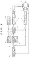
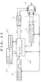
- Fig. 1 is a block diagram showing the whole construction of the first embodiment of the position control system of the present invention.
- motor 2 is a rotary stepping motor, for which a two-phase motor is used in the present embodiment.
- Incrementary type encoder 1 is fixed to a rotary shaft of the step motor 2, and outputs the 2-phase sine wave-like position signals a and b which are different in phase by 90° according to its rotation and a basic position signal z to show the basic position.
- the electronic scale circuit 3 produces a current position signal c which is linearly proportionate to the amount of deviation in rotation from the basic position by the sine wave-like position signals a and b.
- the operating electric angle calculation circuit 6 gives integral and differential compensations, etc. to the error signal e to produce an operating electric angle signal f.
- the first reference position generator 10 generates an open loop position command t for subjecting the stepping motor 2 to open loop position control.
- An angle adjusting circuit 4 outputs an angle adjusting signal d corresponding to a torque angle error caused by a positional error between the stepping motor 2 and the encoder 1.
- Address generator 11 outputs, during the closed loop position control, an address signal r with the inputs of the operating electric angle signal f, the current position signal c, and the angle adjusting signal d, and, during the open loop position control, an address signal r with the input of the open loop reference position command t.
- Function generating circuit 7 calculates microstep current commands sc and ss indicative of 2-phase currents to be supplied to the stepping motor 2 pursuant to certain functions (in this embodiment, sine wave and cosine wave, respectively) according to the address r.
- the 2-phase microstep current commands sc and ss are amplified by the power amplifier 8 and supplied to the stepping motor 2.
- the open loop reference position command t is time-proportionally varied to rotate the stepping motor 2 to the position indicated by the basic position signal z by the open loop control.
- the first reference position generator 10 realizes the reference position command by the use of a kind of counter which shows increase or decrease in its output value in a certain time cycle.
- the open loop reference position command t is used for generating the microstep current commands sc and ss by the address generator 11 and the function generating circuit 7.
- microstep current commands sc and ss are amplified by the power amplifier 8 to rotate the stepping motor 2. Accordingly, the stepping motor 2 is driven stepwise in a certain direction coordinate to the increase of the open loop position command t. And, when the basic position signal z outputted by the encoder 1 through the rotation of the stepping motor 2 reaches the position of change from "L level” to "H level” (or the position of change from "H level” to “L level”), the first reference position generator 10 causes to stop the increase of the increment counter to fix the amount of the reference position command, and the stepping motor 2 also stops at its position.
- the angle adjusting circuit 4 receives the open loop position command t outputted from the first reference position generator 10 at that time and outputs the same as the angle adjusting signal d. Further, at this position, the electronic scale circuit 3 and the second reference position generator 9 are respectively initialized (in this embodiment, to be cleared to zero).
- the position control system performs normal closed loop position control.
- position setting is so made that the closed loop position command s outputted by the second reference position generator 9 agrees with the current position signal c outputted by the electronic scale circuit 3.
- Operating electric angle calculation circuit 6 utilizes the error signal e as an input, provides it with calculation of differential and integral compensations, and outputs an operating electric angle signal f. Operation of the integral compensation is realized by a primary digital filter having a low frequency high gain characteristic.
- the differential compensation is realized by a digital filter having a primary high frequency high gain characteristic and the like.
- the integral compensation operates in a manner to reduce as much as possible the steady-state deviation produced under effect of the friction load and the like, and the differential compensation gives electrical damping to the stepping motor 2. Accordingly, the stepping motor 2 can be quickly set to the target position under the condition of the vibration being suppressed, and further the position control system is stabilized.
- the inputs of the address generator 11 are the generated electric angle signal f, current position signal c, and angle adjusting signal d, and the outputs are the micro-step current commands sc and ss. These micro-step current commands are amplified by the power amplifier 8 as in the case of the initialization of the system to drive the stepping motor 2.
- FIGS. 2 through 5 are the drawings for illustrating the embodiments of each construction element of the first embodiment of the present invention shown in Fig. 1. Detailed explanation will be given hereinafter with reference to these drawings.
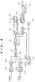
- Fig. 2 is a block diagram showing one embodiment of the address generator 11 and the function generating circuit 7.
- ROMs 24 and 25 are each a PROM containing data to current commands for micro-steps each corresponding to the basic one pitch P of the stepping motor 2 following a certain function (in this embodiment, sine waves of mutually different phases at 90°).
- the means of calculating the address r for these PROMs 24 and 25 are the first adder 21, second adder 22, and upper bit data omitting circuit 23.
- the first adder 21 performs addition of the current position signal c and the operating electric angle signal f.
- the second adder 22 performs addition of the output of the first adder 21 and the angle adjusting signal d.
- the angle adjusting signal d is used to give a certain offset to the address r to PROMs 24 and 25. That is to say, the phases of the micro-step current commands sc and ss shift by the amount corresponding to d. Consequently, even in the case where the mechanical rotational angle of the stepping motor 2 and the phase of a micro-step current command are deviated from each other to cause a phase difference, the size of the angle adjusting signal d is varied in proportion to the phase difference, so that these two factors can be accurately correlated and the stepping motor 2 can be efficiently driven at all times at the torque angle in the most desirable range.
- Upper bit data omitting circuit 23 is not essentially necessary, because, if the operable range of the stepping motor 2 is within the basic one pitch P from the basic position, the output of the second adder 22 may be used as such as the address r of PROMs 24 and 25. However, when the movable range exceeds the basic one pitch P, the circuit 23 is necessary in order to omit the upper bit data for the portion exceeding one pitch out of the output of the second adder 22.
- Fig. 3 is a block diagram showing the first embodiment of the electronic scale circuit 3 in the position control system of Fig. 1.
- the 2-phase sine wave-like position signals a and b from the encoder are converted into the square waves g and h respectively by the wave shaping circuits 30a and 30b and inputted into the pulse dividing circuit 31.
- the square waves g and h are separated into up-count pulse (UP) and down-count pulse (DOWN) by the pulse dividing circuit 31 according to the direction of rotation of the stepping motor 2.
- UP up-count pulse
- DOWN down-count pulse
- the up/down counter 32 By counting them with the up/down counter 32, there can be obtained a current position signal c proportionate to the amount of variation of rotation of the stepping motor.
- the up/down counter 32 has its value unstable at the initial stage of power input, it is cleared to zero at the basic position by the basic position signal z to be inputted to the initial reset input terminal 33 at the initialisation of the system.
- Fig. 4 is a block diagram showing the second embodiment of the electronic scale circuit 3.
- Amplifiers 41a and 41b are the position signal amplifiers for amplifying the 2-phase sine wave-like position signals a and b respectively outputted by the encoder 1.
- Modulation circuits 42a and 42b are the kinds of multipliers for modulating the high frequency carrier signals 46a and 46b respectively with the 2-phase sine wave outputs of the position signal amplifiers 41a and 41b.
- Carrier signal generator 40 effects frequency division of the reference clock signal of the reference oscillator 47 to prepare the carrier signals 46a and 46b. These two carrier signals 46a and 46b are in deviation of phases by 90° to each other, and are inputted to the modulation circuits 42a and 42b from the carrier signal generator 40.
- Adder 43 adds up the modulation outputs of the modulation circuits 42a and 42b.
- Low pass filter 44 eliminates the harmonic components of the modulation output added up with the adder 43 and takes out the fundamental wave component only.
- Wave shaping circuit 45 converts the above fundamental wave into a square wave.
- EA ( ⁇ ) E ⁇ COS (2 ⁇ ⁇ / ⁇ p )
- EB ( ⁇ ) E ⁇ SIN (2 ⁇ ⁇ / ⁇ p )
- ⁇ a rotary angle of the stepping motor 2
- ⁇ p 1 cycle pitch of sine wave to be outputted by the encoder 1
- E an amplitude of the sine wave position signal.
- CA(t) COS(2 ⁇ fct)
- CB(t) SIN(2 ⁇ fct) where, fc is a carrier frequency.
- the signal P(t, ⁇ ) obtained by addition after modulation cannot be utilized as such, it requires to be demodulated and the position information only has to be taken out by separation.
- a demodulation system such that, after converting the signal P(t, ⁇ ) into a square wave with the wave shaping circuit 45, the phase deviation of the signal P(t, ⁇ ) to the carrier signal 46a is directly counted by using the reference clock signal outputted by the reference oscillator 47, by which the position information having high resolution is taken out.
- Counter 48 is a phase difference counter for counting the phase information of the signal P(t, ⁇ ).
- phase difference counter 48 starts to count the reference clock signal by the rise (or decay) of the carrier signal 46a, and continues counting until it detects the rise (or decay) of the signal P (t, ⁇ ). By constituting as such, it is possible to take out the phase information (2 ⁇ / ⁇ p ) contained in the signal P (t, ⁇ ) as a count value of the phase difference counter 48.
- Frequency dividing circuit 40 divides the output of the oscillator 47 to 1/n and outputs the 2-phase carrier signals 46a and 46b.
- the contents of the phase difference counter 48 are n in the maximum, having the phase discriminating capacity only within the range of the 1 cycle pitch ⁇ p of the position signal. Accordingly, in order to make the operation in such a broad range as is necessitated with the actual position control device possible, an up/down counter 50 is provided to count the number at which the position signal has exceeded the 1 cycle pitch ⁇ p .
- Pulse separating circuit 49 separates the pulse into up-count pulse and down-count pulse, respectively, according to each change of the content of the phase difference counter 48 to o ⁇ n or n ⁇ o.
- the up/down counter 50 performs up-count or down-count under the up-count pulse or down-count pulse.
- Terminal 51 is the original point/initial time reset input, in which a basic position signal z showing the basic position is inputted.
- Position counter 52 synthesizes the content of the up/down counter 50 and the content of the phase difference counter 48 to the upper bit part and the lower bit part, respectively, and outputs the position data i.
- the electronic scale circuit 3 requires to be initialized in the initialization of the system. The reason for it is because the value of the position counter 52 becomes unstable after the power input, so that it is necessary to give the initial value corresponding to the basic position.
- an electrical interpolation system as in the embodiment of Fig. 4 is used, it is only the contents of the up/down counter 50 that can be simply initialized (in this embodiment, cleared to zero), and it is not possible to initialize even the contents of the phase difference counter 48 which are the interpolation information in 1 cycle pitch ⁇ p of the sine wave-like position signals a and b.
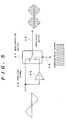
- Fig. 5 is one embodiment of the modulation circuits 42a and 42b.
- Signal 55 is a sine wave output E( ⁇ ) of the position signal amplifier 41a or 41b.
- Amplifier 56 is an inverting amplifier (gain 1).
- Switch 57 is a semiconductor switch controlled by the carrier signal (frequency fc) 46. Semiconductor switch 57 is so constructed as to transmit the position signal E( ⁇ ) as such when the carrier signal 46 is at "H level", and to transmit the inverted position signal -E( ⁇ ) when the carrier signal 46 is at "L level", thereby obtaining a modulation output 58 as illustrated.
- the sine wave-like position signals a and b are converted into the current position signal c having high resolution in proportion to the amount of variation of rotation.
- an encoder having high resolution is difficult to manufacture and expensive.
- sufficiently fine current position signal can readily be obtained even from a relatively low priced encoder having coarse resolution. Accordingly, it becomes possible to make the step width of the stepping motor 2 finer, and to realize a position control system of a higher precision.
- Fig. 6 is a block diagram of the position control system in the second embodiment of the present invention. With respect to the same elements as those shown in Fig. 1, the same numbers have been assigned and description omitted.
- Processing unit 60 employs a micro-processor. The processing unit 60 is operated in accordance with the later described prescribed internal program stored in the ROM range (Read-On-Memory range) of the memory 61.
- Fig. 7 shows a basic flow chart of said program. The ensuing explanation will be taken in accordance with this figure, with limitation to the case where an embodiment shown in Fig. 4 is used for the electronic scale circuit 3.
- Process 70 is a confirmatory process of the operation mode command, in which, for initialization of the system, the step goes to Process 71, and for normal closed loop position control, to Process 80, respectively. After the power input, initialization of the system is firstly selected.
- Process 71 corresponds to the first reference position generator 10.
- This is a processing routine for producing an open loop position command t which increases at intervals of a certain time. Concretely, the content of the open loop reference position command register allocated to a certain address in the RAM range and a constant value k are added, and the result is taken into the open loop reference position command register.
- the constant value k at this time corresponds to the step width in driving the stepping motor 2 in open loop stepping.
- Process 72 corresponds to the upper bit data omitting circuit 23 in the address generator 11, in which, of the contents of the open loop reference position command register, the upper bit data of the portion exceeding the basic 1 pitch P of the stepping motor 2 are subjected to omitting, and the result thereof is stored in the address register allocated to the RAM range.
- Process 73 utilizing the contents of the address register stored in Process 72 as an address to the memory 61, by referring to the function tables of sine wave and cosine wave which are stored in ROM range of the memory 61, the 2-phase signals sc and ss are obtained, and they are respectively outputted to the driving circuit 8.
- the stepping motor 2 rotates by 1 step at the stepping width corresponding to a certain value k.
- Process 74 is a process to confirm whether or not the stepping motor 2 has shifted to the position of the basic position signal z. If the shifting has been completed, the step goes to the process 75, and if not yet completed, after a certain time waiting in process 75, the steps 71 through 74 are repeated. When the step motor 2 reaches the position of the basic position signal z, the electronic scale circuit 3 and the second reference position generator 9 are initialized by the basic position signal z.
- Process 76 the contents of the open loop reference position command register at that time are stored in an angle adjusting signal register allocated to the RAM range as the angle adjusting signal d.
- the position data i which is the output of the position counter 2 in the electronic scale circuit 3, is taken in and stored in the latch register allocated to the RAM range. This latch is defined as zx.
- Processes 80 through 84 are the normal closed loop position control mode processes.
- Process 80 waits an interruption from the timer.
- the timer generates an interruption signal at intervals of a prescribed time ⁇ T, and on interruption the step shifts to Process 81. That is to say, the following processing is performed by the sampling time ⁇ T.
- Process 81 includes the subtraction circuit 54.
- the closed loop reference position command s and the position data i are respectively taken in and stored in the reference position register allocated to the RAM range and the current position register.
- the latch zx stored in the latch register in Process 76 is subtracted from the stored position data i, and the result thereof is stored as the current position signal c in the current position register.
- Process 82 corresponds to the operating electric angle calculation circuit 6.
- a digital filter operation of integral compensation and differential compensation is conducted to produce an operating electric angle amount f, which is stored in the operating electric angle register allocated to the RAM range.
- Process 83 corresponds to the first adder 21, second adder 22, and upper bit data omitting circuit 23 in the function generating circuit 7.
- addition of the data of the current position register and the operating electric angle register is performed, and further the result thereof and the content of the angle adjusting signal memory register are added.
- the upper bit data of the portion in excess of the basic 1 pitch P of the stepping motor 2 is omitted and the result is stored in the above address register.
- Process 84 utilizing the contents of the address register stored as an address to the memory 61, by referring to the function tables of sine wave and cosine wave which are stored in ROM range of the memory 61, the 2-phase signals sc and ss are obtained, and they are respectively outputted to the driving circuit 8. After this process, Processs 80 through 84 are repeatedly executed until a command to shift to a separate mode is given from an external source.
- the simplest torque angle error adjusting system for adjusting a torque angle error caused by the positional error between the stepping motor and the encoder is used. Although they are effective in the case where the stepping motor or the object to be driven by the stepping motor has a small load (friction load, etc.), when it has a large friction load, there is a possibility of taking in an erroneous angle adjusting signal d.
- the third embodiment to be next explained is to cover the above defect, and is more preferred embodiment.
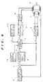
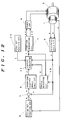
- Fig. 8 is a block diagram showing the whole construction of the third embodiment of the position control system according to the present invention.
- the point of difference from the first embodiment shown in Fig. 1 is only in the angle adjusting circuit 18, so that the following explanation will be limited to the related part.
- the output t of the first reference position generator is not used as a angle adjusting signal d, as shown in the drawing. Using another drawing, the angle adjusting circuit in this embodiment will be explained in detail below.
- Fig. 9 is the first embodiment of the angle adjusting circuit 18 shown in Fig. 8.
- a reference voltage V is inputted.
- the two ends of the variable resistor 12 are connected to the reference voltage V and the ground.
- a voltage v is outputted from the other end.
- A/D converter 13 effects analog - digital conversion of the voltage v.
- an angle adjusting signal d is outputted according to the positional error between the stepping motor 2 and the encoder 1.
- the variable resistor 12 is adjusted so that the result d of A/D conversion of the output voltage v becomes -ed. Since the variable resistor 12 is a kind of the nonvolatile memory, if it is once adjusted, it does not necessitate any adjustment thereafter. If necessary, reference may be made to an angle adjusting signal d which is an output of the A/D converter 13.
- Fig. 10 shows the second embodiment of the angle adjusting circuit 18 as shown in Fig. 8, representing one example of the digital code generating circuit.
- the reference voltage V is inputted.
- Dip switches 16 are provided in the moderate number.
- Fixed resistors 15 are provided in the same number as that of the dip switches 16. The two ends of each fixed resistor are connected to the reference voltage V and the dip switch 16. From each connecting point between the fixed resistor 15 and the dip switch 16, an angle adjusting signal d corresponding to the torque angle error caused by the positional error between the stepping motor 2 and the encoder 1 is outputted.
- angle adjusting signal d has basically the same action as that of the embodiment shown in Fig. 9, detailed explanation thereon is omitted, but adjustment may be so made that the angle adjusting signal d (digital code) to be generated by the setting of the dip switch becomes -ed. In this embodiment as well, if adjustment is first made, no subsequent adjustment is necessary.
- Fig. 11 is a block diagram showing the fourth embodiment of the position control system of the present invention, which shows the construction of the case where, of the construction elements of the third embodiment shown in Fig. 8, the subtractor 5, generating electric angle calculation circuit 6, function generating circuit 7, first reference position generator 10, and address generator 11 are realized by software by using the processing unit 60 and the memory 61.
- the angle adjusting circuit used in the third embodiment and the fourth embodiment of the position control system as explained above permits correct angle ajustment without respect to the load (such as friction load) of the stepping motor or of the object to be driven by the stepping motor, but, due to the necessity for providing a process for adjusting the relative position between the stepping motor and the encoder in manufacture, it is relatively low in mass productivity.
- the fifth embodiment to be described hereinafter is the most preferred embodiment in comparison with the foregoing first to fourth embodiments.
- Fig. 12 is a block diagram showing the fifth embodiment of the position control system of the present invention.
- the portion different from the first embodiment shown in Fig. 1 is only the angle adjusting circuit 19, so that the explanation will be limited to that part.
- the angle adjusting circuit 19 generates an angle adjusting signal d by using the current position signal c and the address signal r.
- the angle adjusting circuit 19 will be given on the angle adjusting circuit 19 below.
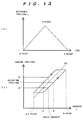
- Fig. 13 is a principle drawing for illustrating the principle of the angle adjusting circuit 19 shown in Fig. 12.
- Fig. 13(a) shows an example of the open loop reference position command t for the case of making the positional error adjustment between the stepping motor 2 and the encoder 1.
- the open loop reference position command t shows an increase in its value time-proportionally from the point A and a decease in its value time-proportionally from the point B.
- the relation between the address signal r and the current position signal c shown by the electronic scale circuit 3 when such an open loop reference position command t is given is shown in Fig. 13(b).
- the reference address has just the central value of the address ⁇ and the address ⁇ . Accordingly, in order to obtain the quantity of the angle adjusting signal d, the address ⁇ and the address ⁇ may be obtained.
- the angle adjusting signal d thus obtained is used at the time of the closed loop position control.
- Fig. 14 is a block diagram showing the construction of one embodiment of the angle adjusting circuit 19.
- the same constitution elements as those shown in Fig. 1 are indicated with the same numbers and explanation thereof is omitted.
- the open loop reference position command t the same one as that of Fig. 13(a) is given.
- the current position signal c varies accordingly.
- Comparing circuit 62 is so constructed that the said current position signal c is compared with the adjusting position signal provided in advance with a suitable value, and, when the two values come to agree, the gate signals g1 and g2 are outputted.
- the gate signal g1 is generated in the course of the variation of the open loop reference position command t from the point A to the point B and the gate signal g2 is generated in the course of the variation of the open loop reference position command t from the point B to the point C.
- the address ⁇ shown in Fig. 13(b) is memorized
- the second latch 64 similarly the address ⁇ is memorized.
- the angle adjusting signal d can be automatically detected by the above construction.
- the fifth embodiment of the position control system as explained above can be readily realized by changing the program to be stored in the memory 61 under the construction of the second embodiment shown in Fig. 6.
- the embodiments of the present invention were explained with the rotary type stepping motor and encoder, but the invention is of course applicable by the use of a driving source of linear movement such as a linear motor and a linear scale.
- a driving source of linear movement such as a linear motor and a linear scale.
- the encoder is directly connected with the rotary shaft of the stepping motor, but it may of course be fixed to a movable means to be driven in accordance with the rotation of the motor.
- the function data having a phase difference at 90° to each other to be stored in the ROM in the function generating circuit are to be prepared by the basic 1 pitch portion of the stepping motor.
- the system may be realized by taking the function data to be stored in the ROM to be a part of 1 pitch portion and generating the rest by an operation with symmetry taken into consideration.
Landscapes
- Engineering & Computer Science (AREA)
- Physics & Mathematics (AREA)
- General Physics & Mathematics (AREA)
- Automation & Control Theory (AREA)
- Human Computer Interaction (AREA)
- Manufacturing & Machinery (AREA)
- Control Of Stepping Motors (AREA)
- Control Of Position Or Direction (AREA)
Claims (15)
- Système de commande de position, comprenant :
un moteur pas à pas (2),
un codeur (1) destiné à produire des signaux polyphasés ayant des phases différentes mutuellement en fonction de la rotation du moteur pas à pas,
un dispositif (3) générateur d'un signal de position actuelle destiné à créer, à partir des signaux polyphasés, un signal de position actuelle représentatif d'une position actuelle du moteur pas à pas,
un dispositif (9) générateur d'une position de référence en boucle fermée destiné à créer une commande de position de référence en boucle fermée de manière que le moteur pas à pas subisse une commande de position en boucle fermée,
un dispositif (5) de calcul d'erreur destiné à calculer la différence entre la commande de position de référence en boucle fermée et le signal de position actuelle et à transmettre un signal d'erreur représentatif de la différence,
un dispositif (6) de calcul d'angle électrique de travail destiné à soumettre le signal d'erreur à un calcul de compensation pour la commande de position en boucle fermée afin qu'il donne un signal d'angle électrique de travail représentatif d'un angle de couple du moteur pas à pas,
un dispositif (7) générateur d'une commande actuelle destiné à créer, à partir du signal d'angle électrique de travail, des commandes de courant exprimées chacune par une fonction mathématique prédéterminée, les commandes de courant étant représentatives des courants polyphasés destinés à être transmis au moteur pas à pas, et
un dispositif de pilotage (8) sensible aux commandes de courant et destiné à créer des courants polyphasés et à les transmettre au moteur pas à pas afin que celui-ci soit piloté,
caractérisé en ce qu'il comporte en outre :
un dispositif (10) générateur d'une position de référence en boucle ouverte destiné à créer une commande de position de référence en boucle ouverte afin que le moteur pas à pas soit soumis à une commande de position en boucle ouverte,
un dispositif (4, 18, 19) d'ajustement d'angle destiné à créer un signal d'ajustement d'angle proportionnel à une erreur d'angle de couple provoquée par une erreur de position entre le moteur pas à pas et le codeur, et
un dispositif (11) générateur d'un signal de commande destiné à créer un signal de commande à partir de la commande de position de référence en boucle ouverte lors de la commande de position en boucle ouverte et à partir du signal d'angle électrique de travail, du signal de position actuelle et du signal d'ajustement d'angle lors de la commande de position en boucle fermée,
le dispositif (7) générateur de commandes de courant étant destiné à créer les commandes de courant à partir du signal de commande. - Système de commande de position selon la revendication 1, dans lequel le dispositif (18) d'ajustement d'angle comprend :
un dispositif (17) destiné à créer une tension de référence V,
un dispositif (12) destiné à transformer la tension de référence V en une tension éventuelle v, et
un dispositif (13) destiné à transformer la tension éventuelle v en un code numérique, ce code numérique étant transmis comme signal d'ajustement d'angle. - Système de commande de position selon la revendication 1, dans lequel le dispositif (18) d'ajustement d'angle comporte un dispositif (14, 15, 16) générateur d'un code numérique destiné à créer un code numérique représentant le signal d'ajustement d'angle.
- Système de commande de position selon la revendication 3, dans lequel le dispositif (14, 15, 16) générateur d'un code numérique comprend :
une source (14) de tension de référence destinée à créer une tension de référence, et
plusieurs circuits d'interruption (15, 16) comprenant chacun une résistance (14) et un interrupteur (16) connectés en série, chacun des circuits interrupteurs étant connecté à une première extrémité à la source de tension de référence et à l'autre extrémité à la masse afin que le code numérique soit obtenu à partir des points de connexion entre les résistances et les interrupteurs. - Système de commande de position selon la revendication 1, dans lequel le dispositif (4, 18, 19) d'ajustement d'angle fait subir au moteur pas à pas des mouvements alternatifs par commande de position en boucle ouverte à l'aide de la commande de position de référence en boucle ouverte pour la détection de l'erreur d'angle de couple.
- Système de commande de position selon la revendication 5, dans lequel le dispositif (19) d'ajustement d'angle comporte :
un dispositif (62) de comparaison du signal de position actuelle à un signal prédéterminé de position d'ajustement lorsque le moteur pas à pas est soumis à des mouvements alternatifs par commande de position en boucle ouverte à l'aide de la commande de position de référence en boucle ouverte, le dispositif de comparaison créant un premier signal de déclenchement lorsque le signal de position actuelle devient égal au signal prédéterminé de position d'ajustement pendant un mouvement du moteur pas à pas vers l'avant et un second signal de déclenchement lorsque le signal de position actuelle devient égal au signal prédéterminé de position d'ajustement pendant un mouvement de retour du moteur pas à pas,
une première mémoire (63) commandée par le premier signal de déclenchement et destinée à conserver le signal de commande au moment où le signal de position actuelle devient égal au signal de position prédéterminé d'ajustement pendant le mouvement d'avance du moteur pas à pas,
une seconde mémoire (64) commandée par le second signal de déclenchement et destinée à contenir le signal de commande au moment où le signal de position actuelle devient égal au signal de position prédéterminée d'ajustement pendant le mouvement de retour du moteur pas à pas, et
un dispositif (65) de calcul de la différence entre le contenu de la première et de la seconde mémoire et de division de la différence calculée par deux pour la formation du signal d'ajustement d'angle. - Système de commande de position selon la revendication 5, dans lequel le dispositif (19) d'ajustement d'angle comprend :
un dispositif (62) de comparaison du signal de commande à un signal prédéterminé de commande d'ajustement lorsque le moteur pas à pas est soumis à des mouvements alternatifs par commande de position en boucle ouverte à l'aide de la commande de position de référence en boucle ouverte, le dispositif de comparaison créant un premier signal de déclenchement lorsque le signal de commande devient égal au signal prédéterminé de commande d'ajustement pendant un mouvement d'avance du moteur pas à pas et un second signal de déclenchement lorsque le signal de commande devient égal au signal prédéterminé de commande d'ajustement pendant un mouvement de retour du moteur pas à pas,
une première mémoire (63) commandée par le premier signal de déclenchement et destinée à conserver le signal de position actuelle au moment où le signal de commande devient égal au signal prédéterminé de commande d'ajustement pendant le mouvement d'avance du moteur pas à pas,
une seconde mémoire (64) commandée par le second signal de déclenchement et destinée à conserver le signal de position actuelle au moment où le signal de commande devient égal au signal prédéterminé de commande d'ajustement pendant le mouvement de retour du moteur pas à pas, et
un dispositif (65) de calcul de la différence entre les contenus de la première et de la seconde mémoire et de division de la différence calculée par deux avec formation du signal d'ajustement d'angle. - Système de commande de position selon la revendication 7, dans lequel le dispositif (19) d'ajustement d'angle comporte en outre un dispositif destiné à multiplier la différence divisée par deux par un coefficient prédéterminé pour la formation du signal d'ajustement d'angle.
- Système de commande de position selon la revendication 1 ou 5, dans lequel le dispositif (3) générateur d'un signal de position actuelle comprend :
un dispositif (47, 40) destiné à créer un signal de porteuse,
un dispositif (42a, 42b, 43) de modulation du signal de porteuse par les signaux polyphasés provenant du codeur afin qu'une porteuse modulée soit obtenue, et
un dispositif (44, 45, 47-54) de démodulation destiné à démoduler l'information de phase de la porteuse modulée afin que le signal de position actuelle soit obtenu. - Système de commande de position selon la revendication 1 ou 5, dans lequel le dispositif (6) de calcul d'angle électrique de travail comprend un filtre de compensation différentielle.
- Système de commande de position selon la revendication 10, dans lequel le dispositif (6) de calcul d'angle électrique de travail comporte en outre un filtre de compensation intégrale destiné à compenser le moteur pas à pas de manière qu'il ne crée pas un écart en régime permanent à la suite d'une commande de position de référence en boucle fermée.
- Système de commande de position selon la revendication 1 ou 5, dans lequel le dispositif (11) générateur du signal de commande comprend :
un dispositif (21, 22) d'addition du signal d'angle électrique de travail, du signal de position actuelle et du signal d'ajustement d'angle, et
un dispositif (23) destiné à omettre les données des bits supérieurs du signal de sortie du dispositif d'addition. - Système de commande de position selon la revendication 1 ou 5, dans lequel le dispositif (7) générateur de commandes de courant comprend une mémoire (24, 25) destinée à contenir plusieurs tables de données ayant chacune des données de commandes de courant représentant la fonction mathématique prédéterminée, la mémoire recevant le signal de commande du dispositif générateur d'un signal de commande comme adresse et transmettant les données de commandes de courant dans chacune des tables de données en fonction de l'adresse.
- Système de commande de position selon la revendication 13, dans lequel les données de commandes de courant de chacune des tables de données représentent une fonction sinusoïdale qui présente une différence de phase par rapport à celles qui sont représentées par les données de commandes de courant d'une autre des tables de données.
- Système de commande de position selon la revendication 1 ou 5, dans lequel le dispositif (10) générateur de position de référence en boucle ouverte, le dispositif (S) de calcul d'erreur, le dispositif (6) de calcul d'angle électrique de travail, le dispositif (4) d'ajustement d'angle et le dispositif (7) générateur de commandes de courant comportent :
une mémoire (61) qui conserve un programme, et
un dispositif (60) de traitement destiné à exécuter le programme conservé dans la mémoire.
Applications Claiming Priority (2)
| Application Number | Priority Date | Filing Date | Title |
|---|---|---|---|
| JP305051/87 | 1987-12-01 | ||
| JP62305051A JPH01148100A (ja) | 1987-12-01 | 1987-12-01 | 位置制御装置 |
Publications (2)
| Publication Number | Publication Date |
|---|---|
| EP0320163A1 EP0320163A1 (fr) | 1989-06-14 |
| EP0320163B1 true EP0320163B1 (fr) | 1993-07-21 |
Family
ID=17940523
Family Applications (1)
| Application Number | Title | Priority Date | Filing Date |
|---|---|---|---|
| EP88311296A Expired - Lifetime EP0320163B1 (fr) | 1987-12-01 | 1988-11-29 | Système de commande de position |
Country Status (5)
| Country | Link |
|---|---|
| US (1) | US4999558A (fr) |
| EP (1) | EP0320163B1 (fr) |
| JP (1) | JPH01148100A (fr) |
| KR (1) | KR910002444B1 (fr) |
| DE (1) | DE3882496T2 (fr) |
Cited By (1)
| Publication number | Priority date | Publication date | Assignee | Title |
|---|---|---|---|---|
| DE102007018808B4 (de) * | 2007-04-20 | 2015-10-01 | Siemens Aktiengesellschaft | Regelanordnung mit Korrektur lageabhängiger systematischer Fehler |
Families Citing this family (33)
| Publication number | Priority date | Publication date | Assignee | Title |
|---|---|---|---|---|
| US4912753A (en) * | 1988-04-04 | 1990-03-27 | Hughes Aircraft Company | Robot axis controller employing feedback and open loop (feedforward) control |
| US4992716A (en) * | 1989-08-02 | 1991-02-12 | Kollmorgen Corp. | Motor control with digital feedback |
| JPH03138524A (ja) * | 1989-10-25 | 1991-06-12 | Matsushita Electric Ind Co Ltd | エンコーダ |
| US5245359A (en) * | 1990-07-02 | 1993-09-14 | Canon Kabushiki Kaisha | Recording apparatus with recording head carriage driving motor control |
| DE69223533T2 (de) * | 1991-03-06 | 1998-07-23 | Hitachi Ltd | Kodierer |
| US5663624A (en) * | 1992-03-05 | 1997-09-02 | Hewlett-Packard Company | Closed-loop method and apparatus for controlling acceleration and velocity of a stepper motor |
| US5208523A (en) * | 1992-03-10 | 1993-05-04 | Wangtek, Inc. | Stepper motor with vernier control mode |
| JPH07154995A (ja) * | 1993-11-29 | 1995-06-16 | Nec Corp | ステップモータ位置決め装置 |
| US5565906A (en) * | 1994-01-13 | 1996-10-15 | Schoonscan, Inc. | Clocking means for bandwise imaging device |
| US5581169A (en) * | 1994-08-31 | 1996-12-03 | Allen-Bradley Company, Inc. | Apparatus used with an inverter/converter eliminating unintended voltage pulses |
| US5760359A (en) * | 1995-07-31 | 1998-06-02 | Matsushita Electric Industrial Co., Ltd. | Motor control apparatus equipped with a controller for controlling rotational position of motor |
| US5684620A (en) * | 1996-01-30 | 1997-11-04 | Schoonscan, Inc. | High resolution imaging system and method of imaging using the same |
| US5790971A (en) * | 1996-06-19 | 1998-08-04 | National Science Council | Frequency-locked stepping position control system |
| KR100242030B1 (ko) * | 1997-11-24 | 2000-02-01 | 윤종용 | 스텝 모터의 제어장치 및 제어방법 |
| US6037735A (en) * | 1999-03-01 | 2000-03-14 | Eastman Kodak Company | Slow-speed servomechanism |
| US6609781B2 (en) | 2000-12-13 | 2003-08-26 | Lexmark International, Inc. | Printer system with encoder filtering arrangement and method for high frequency error reduction |
| US6830399B2 (en) * | 2003-03-14 | 2004-12-14 | Lexmark International, Inc. | Methods and systems for compensation of media indexing errors in a printing device |
| US6873129B1 (en) | 2003-12-16 | 2005-03-29 | Lexmark International Inc. | Method of controlling rotational velocity of a rotatable member during encoder initialization for an imaging apparatus |
| US7102317B2 (en) * | 2004-01-20 | 2006-09-05 | Samsung Electronics Co., Ltd. | Method and apparatus to process an analog encoder signal |
| KR100889961B1 (ko) * | 2007-04-30 | 2009-03-24 | (주)컨벡스 | 스텝 모터 위치 오차 보정 방법 및 시스템 |
| JP2009011087A (ja) * | 2007-06-28 | 2009-01-15 | Murata Mach Ltd | ステッピングモータのマイクロステップ制御方法および電動装置 |
| JP5111031B2 (ja) * | 2007-09-14 | 2012-12-26 | キヤノン株式会社 | 変位検出方法及びモータ制御装置 |
| US20120148373A1 (en) * | 2010-12-13 | 2012-06-14 | Woodings Industrial Corporation | Hydraulic distributor for top charging a blast furnace |
| WO2012114770A1 (fr) * | 2011-02-24 | 2012-08-30 | パナソニック株式会社 | Dispositif, procédé et circuit de commande de mouvement |
| JP5533907B2 (ja) * | 2012-02-07 | 2014-06-25 | 株式会社デンソー | モータ制御装置 |
| JP6721331B2 (ja) * | 2015-12-25 | 2020-07-15 | Thk株式会社 | リニアモータの制御装置及び制御方法 |
| US11072245B2 (en) * | 2016-08-09 | 2021-07-27 | Nidec Corporation | Motor control method, motor control system, and electric power steering system |
| CN110277939B (zh) * | 2018-03-15 | 2022-08-09 | 浙江三花智能控制股份有限公司 | 控制系统及控制方法、带有步进电机的冷媒阀 |
| CN109308006B (zh) * | 2018-10-10 | 2021-06-15 | 北京遥感设备研究所 | 一种位标器用分体式旋转变压器精度补偿方法 |
| CN112994544A (zh) * | 2019-12-16 | 2021-06-18 | 北京大豪科技股份有限公司 | 电机的控制方法、装置、存储介质及电子设备 |
| CN113391551B (zh) * | 2021-06-01 | 2023-08-01 | 佛山市顺德区乐普达电机有限公司 | 电机电角度补偿方法、装置、电子设备及存储介质 |
| CN115913008A (zh) * | 2022-11-30 | 2023-04-04 | 核工业理化工程研究院 | 一种应用于电动真空调节阀的双重控制系统及其控制方法 |
| CN119472152A (zh) * | 2024-08-09 | 2025-02-18 | 歌尔光学科技有限公司 | 调焦机构、投影设备及其控制方法 |
Family Cites Families (6)
| Publication number | Priority date | Publication date | Assignee | Title |
|---|---|---|---|---|
| US3612976A (en) * | 1969-04-09 | 1971-10-12 | Inductosyn Corp | Position control system |
| FR2254056A1 (en) * | 1973-12-10 | 1975-07-04 | Mitsubishi Heavy Ind Ltd | Semi-open loop servo control system - permits closed loop operation until reference value is approached |
| US4027310A (en) * | 1976-01-16 | 1977-05-31 | International Business Machines Corporation | Ink jet line printer |
| FR2396379A1 (fr) * | 1977-07-01 | 1979-01-26 | Thomson Brandt | Lecteur optique de disque d'information muni d'un dispositif d'acces automatique aux informations |
| US4255693A (en) * | 1979-10-29 | 1981-03-10 | International Business Machines Corporation | Closed loop stepper motor circuitry without encoder |
| CA1234622A (fr) * | 1984-08-22 | 1988-03-29 | Sony Corporation | Dispositif de centrage |
-
1987
- 1987-12-01 JP JP62305051A patent/JPH01148100A/ja active Pending
-
1988
- 1988-11-29 DE DE88311296T patent/DE3882496T2/de not_active Expired - Fee Related
- 1988-11-29 US US07/277,198 patent/US4999558A/en not_active Expired - Fee Related
- 1988-11-29 EP EP88311296A patent/EP0320163B1/fr not_active Expired - Lifetime
- 1988-12-01 KR KR1019880016006A patent/KR910002444B1/ko not_active Expired
Cited By (1)
| Publication number | Priority date | Publication date | Assignee | Title |
|---|---|---|---|---|
| DE102007018808B4 (de) * | 2007-04-20 | 2015-10-01 | Siemens Aktiengesellschaft | Regelanordnung mit Korrektur lageabhängiger systematischer Fehler |
Also Published As
| Publication number | Publication date |
|---|---|
| EP0320163A1 (fr) | 1989-06-14 |
| US4999558A (en) | 1991-03-12 |
| DE3882496D1 (de) | 1993-08-26 |
| DE3882496T2 (de) | 1993-11-11 |
| KR890010648A (ko) | 1989-08-09 |
| JPH01148100A (ja) | 1989-06-09 |
| KR910002444B1 (ko) | 1991-04-22 |
Similar Documents
| Publication | Publication Date | Title |
|---|---|---|
| EP0320163B1 (fr) | Système de commande de position | |
| US4715000A (en) | Digital phase-locked loop and frequency measuring device | |
| US5162798A (en) | Resolver to digital converter | |
| US4669024A (en) | Multiphase frequency selective phase locked loop with multiphase sinusoidal and digital outputs | |
| US4072884A (en) | Brushless phase locked servo drive | |
| US4646035A (en) | High precision tunable oscillator and radar equipped with same | |
| US3974428A (en) | Wide range, high accuracy, electronically programmed speed control system | |
| US4475105A (en) | System for detecting mechanical movement | |
| US4556885A (en) | System for detecting position or speed | |
| AU2004236400A1 (en) | Operating method for a coriolis gyroscope and evaluation/adjustment electronic system and pulse modulator suitable therefor | |
| EP0411554B1 (fr) | ContrÔle de moteur avec rebouclage numérique | |
| JPH10311741A (ja) | エンコーダの出力信号処理装置 | |
| US5815424A (en) | Digital angle conversion method | |
| US4266176A (en) | Induction motor slip frequency controller | |
| US4119958A (en) | Method for achieving high accuracy performance from conventional tracking synchro to digital converter | |
| EP0297869A2 (fr) | Appareil pour la détection de la vitesse de rotation d'un objet | |
| EP0285878A1 (fr) | Dispositif de détection de rotation avec un synchro | |
| JPH02136100A (ja) | 位置制御装置 | |
| JPH02136099A (ja) | 位置制御装置 | |
| US4988936A (en) | Correlated coarse position error processor | |
| JP2771910B2 (ja) | 計測回路 | |
| US5136226A (en) | Correlated coarse position error processor | |
| US5289366A (en) | Method and apparatus for correction of a detected faulty actual valve of a signal affected by harmonic vibrations | |
| SU720454A1 (ru) | Преобразователь угла поворота вала в код | |
| RU2047890C1 (ru) | Цифровая система стабилизации скорости |
Legal Events
| Date | Code | Title | Description |
|---|---|---|---|
| PUAI | Public reference made under article 153(3) epc to a published international application that has entered the european phase |
Free format text: ORIGINAL CODE: 0009012 |
|
| AK | Designated contracting states |
Kind code of ref document: A1 Designated state(s): DE FR GB IT NL |
|
| 17P | Request for examination filed |
Effective date: 19891208 |
|
| 17Q | First examination report despatched |
Effective date: 19911223 |
|
| GRAA | (expected) grant |
Free format text: ORIGINAL CODE: 0009210 |
|
| AK | Designated contracting states |
Kind code of ref document: B1 Designated state(s): DE FR GB IT NL |
|
| ITF | It: translation for a ep patent filed | ||
| REF | Corresponds to: |
Ref document number: 3882496 Country of ref document: DE Date of ref document: 19930826 |
|
| ET | Fr: translation filed | ||
| PLBE | No opposition filed within time limit |
Free format text: ORIGINAL CODE: 0009261 |
|
| STAA | Information on the status of an ep patent application or granted ep patent |
Free format text: STATUS: NO OPPOSITION FILED WITHIN TIME LIMIT |
|
| 26N | No opposition filed | ||
| ITPR | It: changes in ownership of a european patent |
Owner name: OFFERTA DI LICENZA AL PUBBLICO |
|
| REG | Reference to a national code |
Ref country code: GB Ref legal event code: 746 Effective date: 19950928 |
|
| REG | Reference to a national code |
Ref country code: FR Ref legal event code: D6 |
|
| PGFP | Annual fee paid to national office [announced via postgrant information from national office to epo] |
Ref country code: FR Payment date: 19971112 Year of fee payment: 10 |
|
| PGFP | Annual fee paid to national office [announced via postgrant information from national office to epo] |
Ref country code: GB Payment date: 19971120 Year of fee payment: 10 |
|
| PGFP | Annual fee paid to national office [announced via postgrant information from national office to epo] |
Ref country code: NL Payment date: 19971130 Year of fee payment: 10 |
|
| PGFP | Annual fee paid to national office [announced via postgrant information from national office to epo] |
Ref country code: DE Payment date: 19971205 Year of fee payment: 10 |
|
| PG25 | Lapsed in a contracting state [announced via postgrant information from national office to epo] |
Ref country code: GB Free format text: LAPSE BECAUSE OF NON-PAYMENT OF DUE FEES Effective date: 19981129 |
|
| PG25 | Lapsed in a contracting state [announced via postgrant information from national office to epo] |
Ref country code: NL Free format text: LAPSE BECAUSE OF NON-PAYMENT OF DUE FEES Effective date: 19990601 |
|
| GBPC | Gb: european patent ceased through non-payment of renewal fee |
Effective date: 19981129 |
|
| PG25 | Lapsed in a contracting state [announced via postgrant information from national office to epo] |
Ref country code: FR Free format text: LAPSE BECAUSE OF NON-PAYMENT OF DUE FEES Effective date: 19990730 |
|
| NLV4 | Nl: lapsed or anulled due to non-payment of the annual fee |
Effective date: 19990601 |
|
| REG | Reference to a national code |
Ref country code: FR Ref legal event code: ST |
|
| PG25 | Lapsed in a contracting state [announced via postgrant information from national office to epo] |
Ref country code: DE Free format text: LAPSE BECAUSE OF NON-PAYMENT OF DUE FEES Effective date: 19990901 |
|
| PG25 | Lapsed in a contracting state [announced via postgrant information from national office to epo] |
Ref country code: IT Free format text: LAPSE BECAUSE OF NON-PAYMENT OF DUE FEES;WARNING: LAPSES OF ITALIAN PATENTS WITH EFFECTIVE DATE BEFORE 2007 MAY HAVE OCCURRED AT ANY TIME BEFORE 2007. THE CORRECT EFFECTIVE DATE MAY BE DIFFERENT FROM THE ONE RECORDED. Effective date: 20051129 |