EP0320318B1 - Stossempfindlicher Karren mit Gitterwerk, bestimmt für den Transport von verschiedenen Produkten - Google Patents
Stossempfindlicher Karren mit Gitterwerk, bestimmt für den Transport von verschiedenen Produkten Download PDFInfo
- Publication number
- EP0320318B1 EP0320318B1 EP88402576A EP88402576A EP0320318B1 EP 0320318 B1 EP0320318 B1 EP 0320318B1 EP 88402576 A EP88402576 A EP 88402576A EP 88402576 A EP88402576 A EP 88402576A EP 0320318 B1 EP0320318 B1 EP 0320318B1
- Authority
- EP
- European Patent Office
- Prior art keywords
- sidewalls
- cart
- foot
- upright
- platform
- Prior art date
- Legal status (The legal status is an assumption and is not a legal conclusion. Google has not performed a legal analysis and makes no representation as to the accuracy of the status listed.)
- Expired - Lifetime
Links
Images


Classifications
-
- B—PERFORMING OPERATIONS; TRANSPORTING
- B62—LAND VEHICLES FOR TRAVELLING OTHERWISE THAN ON RAILS
- B62B—HAND-PROPELLED VEHICLES, e.g. HAND CARTS OR PERAMBULATORS; SLEDGES
- B62B3/00—Hand carts having more than one axis carrying transport wheels; Steering devices therefor; Equipment therefor
- B62B3/002—Hand carts having more than one axis carrying transport wheels; Steering devices therefor; Equipment therefor characterised by a rectangular shape, involving sidewalls or racks
- B62B3/004—Details of doors or cover lids
-
- B—PERFORMING OPERATIONS; TRANSPORTING
- B62—LAND VEHICLES FOR TRAVELLING OTHERWISE THAN ON RAILS
- B62B—HAND-PROPELLED VEHICLES, e.g. HAND CARTS OR PERAMBULATORS; SLEDGES
- B62B2205/00—Hand-propelled vehicles or sledges being foldable or dismountable when not in use
- B62B2205/20—Catches; Locking or releasing an articulation
-
- B—PERFORMING OPERATIONS; TRANSPORTING
- B62—LAND VEHICLES FOR TRAVELLING OTHERWISE THAN ON RAILS
- B62B—HAND-PROPELLED VEHICLES, e.g. HAND CARTS OR PERAMBULATORS; SLEDGES
- B62B2501/00—Manufacturing; Constructional features
- B62B2501/06—Materials used
- B62B2501/067—Wires
Definitions
- the present invention relates to trolleys intended for the transport of various products, and which have two side walls, each constituted by a grid formed by intertwined metal wires, and which are fixed, at their foot, on two opposite sides of a platform horizontal mounted on casters. Furthermore, the front and rear faces of these carriages are generally closed by removable panels. However, a fixed rear wall and a front door hinged on the upright of one of the side walls can also be provided.
- Trolleys of this kind are used for many applications, for example for the transport of goods for the replenishment of a sales store.
- these carriages are usually provided with a closing cover at their upper part.
- these carriages also have side walls as well as front or rear closing elements fitted into the base, the whole of the cage thus formed is subjected to numerous shocks during transport in trucks. It is then extremely common for the side walls to take up additional play at the place of their attachment to the lower platform and for the assembly to deform significantly. It also happens that due to the manipulations undergone during transport, the cage thus deformed then dislodges from the lower platform.
- Trolleys of this kind can also be used for the transport and storage of butchery products, for example pieces of meat already cut. In such a case these carts can be provided mobile shelves. However, here again we encounter the same drawbacks as those described above. It is also the same for all the other usual uses of such trolleys, in particular when these are used for the transport of linen or the like between a place of use and a laundry.
- the object of the present invention is to produce a carriage of the type in question, the structure of which is designed so that it has a very high degree of robustness and can thus without damage be subjected to the shocks which are inevitable during the operations of transport.
- the design of this carriage is such that it is unnecessary to provide thereon an attached cover to ensure its closure at its upper part.
- the trolley according to the invention is characterized in that the two lateral walls of the latter affect the general shape of an inverted L and the edges of their horizontal upper wings are joined and joined together, for example by bolting , the legs of the uprights of these two side walls being also rigidly fixed in vertical sleeves provided at the four corners of the lower platform of the carriage.
- the patent FR-A-2 189 304 describes a carriage which comprises two opposite vertical uprights on which are articulated half-partitions which each fit on the opposite upright.
- the two side walls form, with the lower platform, a perfectly rigid cage which is able to withstand, without damage, repeated shocks. Furthermore, this cage is closed at its upper part which avoids the need to bring a cover on top.
- the assembly thus formed with the platform achieves a one-piece construction which avoids any play at the top or at the bottom and avoids any risk of deformation of this structure.
- the rigid fixing of the foot of the uprights of the side walls can be ensured by means of a nozzle attached to the inside of this foot and which comprises an axial thread intended to receive an assembly bolt whose head rests against the lower end of the corresponding vertical sleeve carried by the lower platform of the trolley.
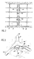
- each of these walls has the general shape of an inverted L. Consequently, the vertical part of each of these walls is extended, at the top, by an upper wing 5 or 6 extending horizontally.
- the two horizontal wings thus provided extend towards one another and they are directly secured to one another, for example by bolting.
- Each of the side walls 3 or 4 is made up by a grid formed by crossed metallic wires and which is surrounded by a metal tube frame.
- the horizontal upper wings 5 and 6 of the side walls are joined together by direct bolting of the corresponding sides 10 and 11 of the two frames 7 and 8, which sides are joined.
- This bolting can be ensured by means of a series of bolts 12.
- the direct joining of the free edges of the upper horizontal wings 5 or 6 of the two side walls 3 and 4 could be ensured by any other appropriate means.
- each upright 19 of the two side walls 3 and 4 is engaged inside a vertical sleeve 14 carried by the lower platform 1, at the location of its corresponding corner.
- a vertical sleeve 14 carried by the lower platform 1, at the location of its corresponding corner.
- Each of these sleeves is secured to the sides 15 of the lower platform by means of a metal gusset 16 welded to these various elements (see FIG. 3).
- the assembly of the foot 13 of each upright with the corresponding sleeve 14 is ensured by means of a metal end piece 17 fitted inside the end of the corresponding upright.
- This tip has a lower flange 18 which is secured by welding with the lower end of the respective upright.
- the end piece 17 has an axial thread 19 inside which is bolted a bolt 20 whose head 21 is supported, by means of a washer 22, against the lower end 23 of the sleeve 24, this end being preferably narrowed.
- the bolt 20 therefore plays the same role as the return screws provided for the assembly of the constituent elements of certain furniture. Therefore there is a close connection of the lower end of each upright 9 inside the sleeve 14 corresponding reception, the lower section of this sleeve being equal or very slightly greater than the outer section of the foot 13 of a amount. Since, moreover, the upper ends of the two side walls 3 and 4 are directly secured to each other by means of their upper wings 5 and 6, a perfectly rigid cage is thus obtained, formed by the platform lower and the two side walls of the carriage. Under these conditions there can be no swinging of the side walls during the transport and handling of the carriage.
- this trolley is suitable for being used for applications involving numerous handling operations and transport with other similar trolleys, inside a truck or other means of transport.
- the front and rear faces of the present carriage can both be open so as to receive, after filling, removable closure panels.
- a fixed vertical wall can also be provided at the rear and a removable closing panel 24 at the front, as is the case in the example shown in FIG. 1.
- a door mounted permanently articulated on the front upright of one of the side walls it would also be possible to provide a door mounted permanently articulated on the front upright of one of the side walls.
- Figures 5 to 7 show variants of the method of securing the foot of the vertical uprights of the side walls with the receiving sleeves carried by the lower platform of the carriage.
- the foot 13a of the corresponding upright 9a is fixed, as before, by means of a nozzle 17 inside which is screwed a tightening bolt 20.
- the foot of the upright 9a is also provided with an attached ring 25 fixed on it by a weld bead 26. This ring is arranged so as to bear on the upper end of the receiving sleeve 14 carried by the lower platform of the carriage.
- FIG. 7 differs from the mounting method shown in FIG. 4 only by the fact that the corresponding assembly endpiece 17c is no longer fixed by welding on the lower end of the respective upright 9c. Indeed in the case considered, the joining of these two elements is ensured by crimping 28 of the foot 13c of this amount in a groove formed for this purpose around the nozzle 17c.
- the trolley according to the invention can be used for many applications and in general for the transport of goods and various products, in particular when this transport implies that such a trolley is placed, with other similar carts, inside a truck or railroad car to be unloaded and rolled around on the ground.
Landscapes
- Engineering & Computer Science (AREA)
- Chemical & Material Sciences (AREA)
- Combustion & Propulsion (AREA)
- Transportation (AREA)
- Mechanical Engineering (AREA)
- Handcart (AREA)
Claims (4)
Applications Claiming Priority (2)
| Application Number | Priority Date | Filing Date | Title |
|---|---|---|---|
| FR8717132 | 1987-12-09 | ||
| FR8717132A FR2624465B1 (fr) | 1987-12-09 | 1987-12-09 | Chariot grillage susceptible de resister aux chocs et destine au transport de produits divers |
Publications (2)
| Publication Number | Publication Date |
|---|---|
| EP0320318A1 EP0320318A1 (de) | 1989-06-14 |
| EP0320318B1 true EP0320318B1 (de) | 1991-03-20 |
Family
ID=9357671
Family Applications (1)
| Application Number | Title | Priority Date | Filing Date |
|---|---|---|---|
| EP88402576A Expired - Lifetime EP0320318B1 (de) | 1987-12-09 | 1988-10-12 | Stossempfindlicher Karren mit Gitterwerk, bestimmt für den Transport von verschiedenen Produkten |
Country Status (5)
| Country | Link |
|---|---|
| US (1) | US4915462A (de) |
| EP (1) | EP0320318B1 (de) |
| DE (2) | DE3862109D1 (de) |
| ES (1) | ES2021860B3 (de) |
| FR (1) | FR2624465B1 (de) |
Families Citing this family (18)
| Publication number | Priority date | Publication date | Assignee | Title |
|---|---|---|---|---|
| AU632786B2 (en) * | 1989-02-23 | 1993-01-14 | James Frederick Glover | A movable stackable load carrying vehicle |
| DE3917279C2 (de) * | 1989-05-25 | 2003-11-27 | Fechtel Transportgeraete Gmbh | Transportwagen oder -plattform |
| FR2689078A1 (fr) * | 1992-03-25 | 1993-10-01 | Bolacho Jean | Chariot de manutention démontable, notamment pour le transport de plis et de colis postaux. |
| FR2695926B1 (fr) * | 1992-09-18 | 1994-12-09 | Caddie Atel Reunis | Dispositif de fixation de panneau pour conteneur roulant, panneau amovible et conteneur roulant correspondants. |
| US5573124A (en) * | 1994-11-08 | 1996-11-12 | Frost; Michael J. | High density showroom storage and display rack |
| USD409811S (en) * | 1997-12-19 | 1999-05-11 | Bekaert Handling & Display Ltd. | Roll container |
| US6241107B1 (en) * | 1998-09-28 | 2001-06-05 | Michael C. Boyer | Modular ventilated storage system |
| US6062402A (en) * | 1999-07-16 | 2000-05-16 | Reborn Products Co., Ltd. | Modular merchandising display rack |
| US6669036B1 (en) * | 1999-10-13 | 2003-12-30 | Frank Yang | Modular storage assembly |
| US7407238B2 (en) * | 2005-05-03 | 2008-08-05 | Innovative Product Achievements | Dispensers with removable storage cartridges |
| CA2607711C (en) * | 2005-05-12 | 2015-04-14 | Alexandre De La Chevrotiere | Moment-resisting joint and system |
| US20070138158A1 (en) * | 2005-12-21 | 2007-06-21 | Young Steven B | Steel mesh welding stock rack |
| US7448634B1 (en) | 2006-03-16 | 2008-11-11 | Bart Raub | Collapsible display rack |
| USD546019S1 (en) * | 2006-03-22 | 2007-07-03 | K. Hartwall Limited | Roll container |
| EP2067686A1 (de) * | 2007-12-06 | 2009-06-10 | AB Mauri Netherlands B.V. | Transportvorrichtung für Rahmschaum |
| US8667633B2 (en) | 2008-10-06 | 2014-03-11 | Alexandre de la Chevrotiere | Structural assemblies for constructing bridges and other structures |
| CN102849095A (zh) * | 2012-08-01 | 2013-01-02 | 张家港市恒美纺织有限公司 | 一种运丝车 |
| US10842263B1 (en) * | 2019-12-27 | 2020-11-24 | Tong-Fu Chen | Combinative shelving unit |
Family Cites Families (8)
| Publication number | Priority date | Publication date | Assignee | Title |
|---|---|---|---|---|
| US2981440A (en) * | 1958-06-23 | 1961-04-25 | Commercial Wire Products Compa | Wire bottle carrier |
| US3315835A (en) * | 1963-02-25 | 1967-04-25 | Reynolds Metals Co | Collapsible stacking crate |
| FR2189304B1 (de) * | 1972-06-22 | 1976-01-16 | Amca Fr | |
| US3834549A (en) * | 1972-09-25 | 1974-09-10 | Gordon Tube Prod Co Inc | Structural system |
| US3977529A (en) * | 1974-06-03 | 1976-08-31 | Mcmillin Wire & Plating, Inc. | Display rack |
| FI66529C (fi) * | 1982-02-25 | 1984-11-12 | Nokia Oy Ab | Staellning saosom skjutvagn eller hylla |
| US4509805A (en) * | 1982-08-09 | 1985-04-09 | Metropolitan Wire Corporation | Enclosed shelving |
| US4632473A (en) * | 1983-10-24 | 1986-12-30 | R. C. Smith Company | Cabinet assembly |
-
1987
- 1987-12-09 FR FR8717132A patent/FR2624465B1/fr not_active Expired - Fee Related
-
1988
- 1988-10-12 DE DE8888402576T patent/DE3862109D1/de not_active Expired - Fee Related
- 1988-10-12 EP EP88402576A patent/EP0320318B1/de not_active Expired - Lifetime
- 1988-10-12 ES ES88402576T patent/ES2021860B3/es not_active Expired - Lifetime
- 1988-11-02 DE DE8813677U patent/DE8813677U1/de not_active Expired
- 1988-12-08 US US07/281,454 patent/US4915462A/en not_active Expired - Lifetime
Also Published As
| Publication number | Publication date |
|---|---|
| EP0320318A1 (de) | 1989-06-14 |
| ES2021860B3 (es) | 1991-11-16 |
| US4915462A (en) | 1990-04-10 |
| DE8813677U1 (de) | 1988-12-22 |
| DE3862109D1 (de) | 1991-04-25 |
| FR2624465A1 (fr) | 1989-06-16 |
| FR2624465B1 (fr) | 1990-03-23 |
Similar Documents
| Publication | Publication Date | Title |
|---|---|---|
| EP0320318A1 (de) | Stossempfindlicher Karren mit Gitterwerk, bestimmt für den Transport von verschiedenen Produkten | |
| EP0337043B1 (de) | Einkaufswagen mit schwenkbarem Korb | |
| EP0202135B1 (de) | Einkaufswagen mit abnehmbaren Behältern zum Gebrauch für Supermarktkunden | |
| FR2645449A1 (fr) | Chariot de golf telescopique et repliable | |
| FR2962953A1 (fr) | Extension laterale rabattable attenante a au moins un plan de chargement d'un vehicule porte-charges | |
| EP0113260B1 (de) | Transportwagen, insbesondere für die Kundschaft von Selbstbedienungsläden | |
| FR2562019A1 (fr) | Dispositif combine a chariot et panier pour denrees diverses | |
| EP0402551A1 (de) | Stapelbarer Einkaufswagen mit einer einziehbaren Ablage unter dem Transportkorb | |
| FR2492768A1 (fr) | Chariot destine a la manutention et au transport de diverses marchandises | |
| EP0036817B1 (de) | Innere Einrichtung für ein Fahrzeug, z.B. für einen faltbaren Wohnwagen | |
| EP0349398A1 (de) | Schaucontainer | |
| EP0320319B1 (de) | Handwagen aus beweglichen Metallplatten für den Transport von verschiedenen Produkten | |
| FR2550150A1 (fr) | Chariot de transport de marchandises pouvant etre superpose avec des chariots identiques | |
| FR2687373A1 (fr) | Palette de manutention demontable. | |
| FR2747634A1 (fr) | Chariot individuel de transport de marchandises et contenant amovible destine a etre utilise avec un tel chariot | |
| FR2599063A1 (fr) | Supports repliables et autoverrouillants de panneaux indicateurs | |
| EP0057800A1 (de) | Mit einer in einer hochgestellten Lage wirksamen Verrieglungseinrichtung versehenes schwenkbares Regal, insbesondere für faltbare Behälter und für Lager-Auffüllwagen in Warenhäusern | |
| FR2610273A1 (fr) | Chariot de transport, notamment pour la clientele des magasins a libre-service, et accessoire pour un tel chariot | |
| FR2629780A1 (fr) | Chariot d'achat, de type emboitable | |
| FR2567737A1 (fr) | Panneau pour la fermeture d'un receptacle de stockage ou de transport, ou d'un meuble de rangement ou similaire | |
| FR2770192A1 (fr) | Chariot individuel de transport de marchandises | |
| EP0491595A1 (de) | Stapelbarer Einkaufswagen mit Transportkorb und Vorrichtung zur Ablage von Kasten oder anderem Gut | |
| FR2789959A1 (fr) | Chariot emboitable de constitution simple et robuste, notamment adapte a recevoir des objets volumineux | |
| CH665809A5 (fr) | Etagere amovible d'un chariot de manutention. | |
| FR2689078A1 (fr) | Chariot de manutention démontable, notamment pour le transport de plis et de colis postaux. |
Legal Events
| Date | Code | Title | Description |
|---|---|---|---|
| PUAI | Public reference made under article 153(3) epc to a published international application that has entered the european phase |
Free format text: ORIGINAL CODE: 0009012 |
|
| AK | Designated contracting states |
Kind code of ref document: A1 Designated state(s): BE DE ES IT LU NL |
|
| 17P | Request for examination filed |
Effective date: 19890607 |
|
| 17Q | First examination report despatched |
Effective date: 19900905 |
|
| ITF | It: translation for a ep patent filed | ||
| GRAA | (expected) grant |
Free format text: ORIGINAL CODE: 0009210 |
|
| AK | Designated contracting states |
Kind code of ref document: B1 Designated state(s): BE DE ES IT LU NL |
|
| REF | Corresponds to: |
Ref document number: 3862109 Country of ref document: DE Date of ref document: 19910425 |
|
| PG25 | Lapsed in a contracting state [announced via postgrant information from national office to epo] |
Ref country code: LU Free format text: LAPSE BECAUSE OF NON-PAYMENT OF DUE FEES Effective date: 19911031 |
|
| PLBE | No opposition filed within time limit |
Free format text: ORIGINAL CODE: 0009261 |
|
| STAA | Information on the status of an ep patent application or granted ep patent |
Free format text: STATUS: NO OPPOSITION FILED WITHIN TIME LIMIT |
|
| 26N | No opposition filed | ||
| PGFP | Annual fee paid to national office [announced via postgrant information from national office to epo] |
Ref country code: BE Payment date: 19941011 Year of fee payment: 7 |
|
| PGFP | Annual fee paid to national office [announced via postgrant information from national office to epo] |
Ref country code: DE Payment date: 19941014 Year of fee payment: 7 |
|
| PGFP | Annual fee paid to national office [announced via postgrant information from national office to epo] |
Ref country code: ES Payment date: 19941028 Year of fee payment: 7 |
|
| PGFP | Annual fee paid to national office [announced via postgrant information from national office to epo] |
Ref country code: NL Payment date: 19941031 Year of fee payment: 7 |
|
| PG25 | Lapsed in a contracting state [announced via postgrant information from national office to epo] |
Ref country code: ES Free format text: LAPSE BECAUSE OF EXPIRATION OF PROTECTION Effective date: 19951013 |
|
| PG25 | Lapsed in a contracting state [announced via postgrant information from national office to epo] |
Ref country code: BE Effective date: 19951031 |
|
| BERE | Be: lapsed |
Owner name: ATELIERS REUNIS CADDIE Effective date: 19951031 |
|
| PG25 | Lapsed in a contracting state [announced via postgrant information from national office to epo] |
Ref country code: NL Effective date: 19960501 |
|
| PG25 | Lapsed in a contracting state [announced via postgrant information from national office to epo] |
Ref country code: DE Effective date: 19960702 |
|
| NLV4 | Nl: lapsed or anulled due to non-payment of the annual fee |
Effective date: 19960501 |
|
| REG | Reference to a national code |
Ref country code: ES Ref legal event code: FD2A Effective date: 19990601 |
|
| PG25 | Lapsed in a contracting state [announced via postgrant information from national office to epo] |
Ref country code: IT Free format text: LAPSE BECAUSE OF NON-PAYMENT OF DUE FEES;WARNING: LAPSES OF ITALIAN PATENTS WITH EFFECTIVE DATE BEFORE 2007 MAY HAVE OCCURRED AT ANY TIME BEFORE 2007. THE CORRECT EFFECTIVE DATE MAY BE DIFFERENT FROM THE ONE RECORDED. Effective date: 20051012 |