EP0320360A2 - Vorrichtung zum Bearbeiten von Schwartenkrettern auf Standardabmessungen zur Wertsteigerung - Google Patents
Vorrichtung zum Bearbeiten von Schwartenkrettern auf Standardabmessungen zur Wertsteigerung Download PDFInfo
- Publication number
- EP0320360A2 EP0320360A2 EP88403076A EP88403076A EP0320360A2 EP 0320360 A2 EP0320360 A2 EP 0320360A2 EP 88403076 A EP88403076 A EP 88403076A EP 88403076 A EP88403076 A EP 88403076A EP 0320360 A2 EP0320360 A2 EP 0320360A2
- Authority
- EP
- European Patent Office
- Prior art keywords
- cutting means
- flitches
- conveyor
- rotor
- slabs
- Prior art date
- Legal status (The legal status is an assumption and is not a legal conclusion. Google has not performed a legal analysis and makes no representation as to the accuracy of the status listed.)
- Withdrawn
Links
Images

Classifications
-
- B—PERFORMING OPERATIONS; TRANSPORTING
- B27—WORKING OR PRESERVING WOOD OR SIMILAR MATERIAL; NAILING OR STAPLING MACHINES IN GENERAL
- B27C—PLANING, DRILLING, MILLING, TURNING OR UNIVERSAL MACHINES FOR WOOD OR SIMILAR MATERIAL
- B27C5/00—Machines designed for producing special profiles or shaped work, e.g. by rotary cutters; Equipment therefor
- B27C5/08—Rounding machines
-
- B—PERFORMING OPERATIONS; TRANSPORTING
- B27—WORKING OR PRESERVING WOOD OR SIMILAR MATERIAL; NAILING OR STAPLING MACHINES IN GENERAL
- B27M—WORKING OF WOOD NOT PROVIDED FOR IN SUBCLASSES B27B - B27L; MANUFACTURE OF SPECIFIC WOODEN ARTICLES
- B27M1/00—Working of wood not provided for in subclasses B27B - B27L, e.g. by stretching
- B27M1/08—Working of wood not provided for in subclasses B27B - B27L, e.g. by stretching by multi-step processes
Definitions
- the present invention relates to an installation for processing the files for their recovery.
- dosing The piece of wood which is detached when washing a log at the start of sawing is called "dosing".
- the backs have a flat face erected with a saw and the rest of the surface, called the back, is a segment of the log.
- the backings obviously have an irregular shape and dimensions which make them unusable, except for making charcoal or, after costly reprocessing, small strips.
- the present invention proposes to enhance the backing by making, economically, from the latter, new products of standardized shape and dimensions.
- This object is achieved by the invention in the sense that it provides a treatment installation which comprises, in a manner known per se, conveyor means adapted to receive, route and evacuate the slabs before, during and after treatment. , pressing means applying the flat face of the backing against the conveyor means, and cutting means capable of acting on the back of the backing.
- the installation is characterized in that it comprises first cutting means located on either side of the conveyor means, in the vicinity of their receiving end, which first cutting means are adapted to pre-align the slabs to create surfaces reference, and second cutting means mounted on the internal face of a hollow rotor through which the conveyor passes, downstream of the first cutting means, seen in the conveying direction, said second cutting means being adapted to give a surface standard convex on the back of the pre-aligned backs.
- the first cutting means can consist of strawberries.
- the second cutting means can also be constituted by cutters or by fixed knives depending on the hardness of the treated wood.
- the pressing means are advantageously made up, in the amount of the rotor, seen in the direction of conveying the slabs, of cylinders with notched periphery which act on the slabs before treatment and, downstream of the rotor, of cylinders with concave periphery which act on the slabs after treatment.
- the slices of the treated slabs can be flat as mentioned above, they can also include male and / or female reliefs allowing them to be nested side by side.
- the installation comprises, downstream of the rotor, seen in the direction of conveying the slabs, appropriate means of tipping.
- the installation includes a frame 1 supporting an endless conveyor 2 driven, by means of a belt 3, by a motor 4.
- the conveyor 2 has one end 5 and a discharge end 6, so that the slabs are conveyed in the direction indicated by the arrows F.
- the frame 1 also supports hydraulic or pneumatic means 7 adapted to apply notched pressure cylinders 8a and 8b on the slabs resting on the conveyor 2.
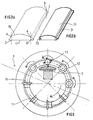
- FIG. 2 The structure of the rotor emerges more clearly from FIG. 2 where it can be seen that its internal face is furnished with milling cutters 12 or fixed knives 13, the choice between milling cutters and fixed knives being dictated by the hardness of the treated wood.
- a pair of pressing cylinders 14a and 14b is provided downstream of the rotor 9, the concave periphery of which corresponds, in curvature, to the convexity imparted to the backings by the cutting members of the rotor 9.
- the dosage is as shown in FIG. 2a, that is to say that it has a flat surface 17 and an irregularly roughly convex back 18.
- the first step is to create reference surfaces such as A, B, C, D on each side of the backing to ensure proper guidance and centering of the piece of wood in the rotor.
- the cutting members 12 or 13 of the rotor then create the standardized convex surface 20 of the finished product as shown in FIG. 2b.
- the planing means 15 form in the reference surfaces A, B, C, D, respectively, a tongue 21 and a groove 22.
- the finished product is likely to be used as interior paneling, as exterior trim for garden sheds (its rounded appearance pronounced of that of logs), as cladding of construction sites for poor quality wood (for example when it is of the sapwood of the oak), the undulating configuration of the resulting walls discouraging the display.
- the product according to the invention can also be used for the manufacture of packaging.
Landscapes
- Life Sciences & Earth Sciences (AREA)
- Engineering & Computer Science (AREA)
- Mechanical Engineering (AREA)
- Wood Science & Technology (AREA)
- Forests & Forestry (AREA)
- Threshing Machine Elements (AREA)
Applications Claiming Priority (2)
| Application Number | Priority Date | Filing Date | Title |
|---|---|---|---|
| FR8716978A FR2624046B1 (fr) | 1987-12-07 | 1987-12-07 | Installation de mise a dimensions standard des dosses en vue de leur valorisation |
| FR8716978 | 1987-12-07 |
Publications (2)
| Publication Number | Publication Date |
|---|---|
| EP0320360A2 true EP0320360A2 (de) | 1989-06-14 |
| EP0320360A3 EP0320360A3 (de) | 1991-05-08 |
Family
ID=9357559
Family Applications (1)
| Application Number | Title | Priority Date | Filing Date |
|---|---|---|---|
| EP19880403076 Withdrawn EP0320360A3 (de) | 1987-12-07 | 1988-12-06 | Vorrichtung zum Bearbeiten von Schwartenkrettern auf Standardabmessungen zur Wertsteigerung |
Country Status (2)
| Country | Link |
|---|---|
| EP (1) | EP0320360A3 (de) |
| FR (1) | FR2624046B1 (de) |
Cited By (1)
| Publication number | Priority date | Publication date | Assignee | Title |
|---|---|---|---|---|
| CN107042549A (zh) * | 2017-04-28 | 2017-08-15 | 重庆宜居门业有限公司 | 木材切割装置 |
Family Cites Families (6)
| Publication number | Priority date | Publication date | Assignee | Title |
|---|---|---|---|---|
| DE454742C (de) * | 1928-01-17 | Anton Benz Fa | Vorrichtung zur Bearbeitung von Messerschalen aus Knochen, Holz o. dgl. | |
| US1794116A (en) * | 1926-05-17 | 1931-02-24 | Fed Cooperage Corp | Knockdown barrel and method and machine for forming same |
| FR1265736A (fr) * | 1960-08-23 | 1961-06-30 | Kieserling & Albrecht | Machine d'usinage de surface notamment pour épluchage |
| US4372357A (en) * | 1979-01-05 | 1983-02-08 | Globe Machine Manufacturing Company | Machine for profiling wood panel to simulate lap siding |
| FR2495045A1 (fr) * | 1980-12-01 | 1982-06-04 | Claude Yvan | Procede pour la valorisation de sous produits massifs de scierie et produits obtenus selon le procede |
| US4519429A (en) * | 1983-07-05 | 1985-05-28 | Dreese Charles H | Log shaper |
-
1987
- 1987-12-07 FR FR8716978A patent/FR2624046B1/fr not_active Expired - Lifetime
-
1988
- 1988-12-06 EP EP19880403076 patent/EP0320360A3/de not_active Withdrawn
Cited By (1)
| Publication number | Priority date | Publication date | Assignee | Title |
|---|---|---|---|---|
| CN107042549A (zh) * | 2017-04-28 | 2017-08-15 | 重庆宜居门业有限公司 | 木材切割装置 |
Also Published As
| Publication number | Publication date |
|---|---|
| EP0320360A3 (de) | 1991-05-08 |
| FR2624046B1 (fr) | 1992-02-07 |
| FR2624046A1 (fr) | 1989-06-09 |
Similar Documents
| Publication | Publication Date | Title |
|---|---|---|
| FR2551695A1 (fr) | Dispositif d'entaillage pour couper des couches selectionnees de flans de carton a epaisseurs multiples | |
| FR2461559A1 (fr) | Procede pour debiter par usinage des troncs d'arbres en produits en bois usines sur toutes leurs faces et dispositifs pour sa mise en oeuvre | |
| FR2611535A1 (fr) | Dispositif de coupe pour des machines destinees a reduire en particules un materiau | |
| FR2589386A1 (fr) | Chaine a scier | |
| CH644250A5 (fr) | Procede de decoupage de demi-coques formees dans une feuille du type gaufre. | |
| EP0125175B1 (de) | Vorrichtung zum Schneiden von ununterbrochen hergestellten Röhren aus Pappe | |
| FR2573687A1 (fr) | Dispositif de cisaillage en biais de l'extremite d'un tube | |
| FR2458365A1 (fr) | Procede et dispositif pour scier les troncs d'arbres | |
| EP0320360A2 (de) | Vorrichtung zum Bearbeiten von Schwartenkrettern auf Standardabmessungen zur Wertsteigerung | |
| BE1004756A5 (fr) | Procede d'obtention de bois d'oeuvre a partir de troncs d'arbre ou de planches de sciage de tronc, et dispositif pour la mise en oeuvre du procede. | |
| FR2605028A1 (fr) | Engin de fraisage pour creuser des tranchees dans le sol. | |
| FR2667005A1 (fr) | Installation de sciage de profiles en acier, en particulier de profiles lourds pour des constructions metalliques. | |
| FR2502544A1 (fr) | Appareil de fabrication d'un tube de papier | |
| FR3048898A1 (fr) | Procede et installation de traitement de panneau ou plaque | |
| EP0080408B1 (de) | Maschine zum Herstellen von Schindeln | |
| FR2547762A3 (fr) | Machine-outil a bois raboteuse d'epaisseur | |
| FR2470664A1 (fr) | Scie mecanique a grumes equipee d'un dispositif a morceler les dosses en copeaux et son procede de mise en oeuvre | |
| FR2576826A1 (fr) | Procede de fabrication de bouchons en liege naturel | |
| FR2809143A1 (fr) | Dispositif d'assemblage de panneaux de bois | |
| CH638130A5 (en) | Cutting link for a saw chain | |
| BE1005021A6 (fr) | Methode et dispositif de fabrication de mobilier. | |
| FR2661351A1 (fr) | Machine et installation de decoupe de produits en plaque, notamment pour la realisation de canapes. | |
| FR2956343A1 (fr) | Poste de decoupe de quartiers de bois de chauffage en buches de longueurs predeterminees ou reglables | |
| FR2661360A1 (fr) | Procede et dispositif pour reduire en copeaux des pieces allongees en bois. | |
| FR2469990A1 (fr) | Separateur de produit lateral, ou rive flacheuse, pour installation de sciage |
Legal Events
| Date | Code | Title | Description |
|---|---|---|---|
| PUAI | Public reference made under article 153(3) epc to a published international application that has entered the european phase |
Free format text: ORIGINAL CODE: 0009012 |
|
| AK | Designated contracting states |
Kind code of ref document: A2 Designated state(s): AT BE CH DE ES FR GB GR IT LI LU NL SE |
|
| PUAL | Search report despatched |
Free format text: ORIGINAL CODE: 0009013 |
|
| AK | Designated contracting states |
Kind code of ref document: A3 Designated state(s): AT BE CH DE ES FR GB GR IT LI LU NL SE |
|
| STAA | Information on the status of an ep patent application or granted ep patent |
Free format text: STATUS: THE APPLICATION IS DEEMED TO BE WITHDRAWN |
|
| 18D | Application deemed to be withdrawn |
Effective date: 19911109 |