EP0321048B1 - Hochleistungslichtquelle für Kameras - Google Patents
Hochleistungslichtquelle für Kameras Download PDFInfo
- Publication number
- EP0321048B1 EP0321048B1 EP88202859A EP88202859A EP0321048B1 EP 0321048 B1 EP0321048 B1 EP 0321048B1 EP 88202859 A EP88202859 A EP 88202859A EP 88202859 A EP88202859 A EP 88202859A EP 0321048 B1 EP0321048 B1 EP 0321048B1
- Authority
- EP
- European Patent Office
- Prior art keywords
- camera
- input
- optical
- optical system
- elementary sources
- Prior art date
- Legal status (The legal status is an assumption and is not a legal conclusion. Google has not performed a legal analysis and makes no representation as to the accuracy of the status listed.)
- Expired - Lifetime
Links
- 230000003287 optical effect Effects 0.000 claims description 10
- 210000001747 pupil Anatomy 0.000 claims description 8
- 238000005286 illumination Methods 0.000 claims description 3
- 230000003595 spectral effect Effects 0.000 claims description 2
- 238000013459 approach Methods 0.000 description 3
- 238000005259 measurement Methods 0.000 description 3
- 230000008878 coupling Effects 0.000 description 2
- 238000010168 coupling process Methods 0.000 description 2
- 238000005859 coupling reaction Methods 0.000 description 2
- 230000004907 flux Effects 0.000 description 2
- 230000005679 Peltier effect Effects 0.000 description 1
- 238000000149 argon plasma sintering Methods 0.000 description 1
- 230000005540 biological transmission Effects 0.000 description 1
- 238000010586 diagram Methods 0.000 description 1
- 210000000887 face Anatomy 0.000 description 1
- 238000002347 injection Methods 0.000 description 1
- 239000007924 injection Substances 0.000 description 1
- 230000035939 shock Effects 0.000 description 1
Images

Classifications
-
- H—ELECTRICITY
- H01—ELECTRIC ELEMENTS
- H01S—DEVICES USING THE PROCESS OF LIGHT AMPLIFICATION BY STIMULATED EMISSION OF RADIATION [LASER] TO AMPLIFY OR GENERATE LIGHT; DEVICES USING STIMULATED EMISSION OF ELECTROMAGNETIC RADIATION IN WAVE RANGES OTHER THAN OPTICAL
- H01S3/00—Lasers, i.e. devices using stimulated emission of electromagnetic radiation in the infrared, visible or ultraviolet wave range
- H01S3/23—Arrangements of two or more lasers not provided for in groups H01S3/02 - H01S3/22, e.g. tandem arrangements of separate active media
- H01S3/2383—Parallel arrangements
-
- G—PHYSICS
- G01—MEASURING; TESTING
- G01S—RADIO DIRECTION-FINDING; RADIO NAVIGATION; DETERMINING DISTANCE OR VELOCITY BY USE OF RADIO WAVES; LOCATING OR PRESENCE-DETECTING BY USE OF THE REFLECTION OR RERADIATION OF RADIO WAVES; ANALOGOUS ARRANGEMENTS USING OTHER WAVES
- G01S17/00—Systems using the reflection or reradiation of electromagnetic waves other than radio waves, e.g. lidar systems
- G01S17/87—Combinations of systems using electromagnetic waves other than radio waves
- G01S17/875—Combinations of systems using electromagnetic waves other than radio waves for determining attitude
-
- G—PHYSICS
- G01—MEASURING; TESTING
- G01S—RADIO DIRECTION-FINDING; RADIO NAVIGATION; DETERMINING DISTANCE OR VELOCITY BY USE OF RADIO WAVES; LOCATING OR PRESENCE-DETECTING BY USE OF THE REFLECTION OR RERADIATION OF RADIO WAVES; ANALOGOUS ARRANGEMENTS USING OTHER WAVES
- G01S7/00—Details of systems according to groups G01S13/00, G01S15/00, G01S17/00
- G01S7/48—Details of systems according to groups G01S13/00, G01S15/00, G01S17/00 of systems according to group G01S17/00
- G01S7/481—Constructional features, e.g. arrangements of optical elements
- G01S7/4814—Constructional features, e.g. arrangements of optical elements of transmitters alone
- G01S7/4815—Constructional features, e.g. arrangements of optical elements of transmitters alone using multiple transmitters
Definitions
- the invention relates to a camera incorporating a high-power illuminating device for carrying out measurements of direction, distance and relative attitude between two objects one of which is equipped with said device, said camera forming the image of the other object on a detector through an input optic and an optical filter of determined spectral band, said device consisting of several elementary sources each comprising a collimating optic for adjusting the field of view of each of said sources to that of the camera input optics.
- a device of this kind finds an application for example in the approaches of meeting between two space vehicles of which one called “hunter” seeks to join the other called “target”.
- the coupling of the two vehicles must be possible with the lowest possible mechanical shock so as not to modify the orbital conditions of the target too much.
- the hunter must take into account the target's theoretical orbit early enough to approach it with the right speed and above all with the right attitude.
- This equipment consists of a camera fitted with a light emitter which emits along the same axis and in the same field as that of the camera a certain cone of light projected on the target where retroflectors have been placed, that is to say small mirrors with three faces (or cubic corners) which return the reflected beam in the direction of the incident beam whatever the position that they occupy in space.
- the laser diodes usually used as light emitters require collimating optics to adapt the angle of the emission cone to the field of view of the camera.
- a transmitter In the case of application to the space rendezvous between two vehicles, a transmitter is required which is powerful enough for the light flux coming from the retroflectors and which strikes the camera to be greater than that emitted by the sun.
- the object of the invention is to overcome this difficulty by means of a device ensuring the coupling of several elementary sources and allowing the modulation of the high transmission power thus produced and obtaining self-redundancy in the event of failure of one or more of these sources.
- the device of the invention is remarkable in that said elementary sources are regularly distributed in a ring around the pupil of said input optics, the light beam coming from the collimation optics of each of said sources being focused.
- a deflection mirror placed opposite each source on a faceted mirror surrounding said pupil of the input optics and comprising as many facets as light sources, each facet being inclined d 'a angle such that the direction of the reflected beam is collinear with the direction of the camera's field of view, so that the light beams coming from said mirror facets are almost superimposable all around the optical axis of the camera.
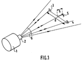
- Figure 1 shows the block diagram of the measuring device.
- FIG. 2 represents a longitudinal section of the illuminator of the invention associated with the camera.
- FIG. 1 gives the principle.
- the camera 1 equipped with its illuminator 2 and on the other there are distributed three patterns of non-coplanar retroreflectors 3, 4 and 5 in the emission cone 6 of the illuminator.
- the parts of the beams returned to themselves by the retro-reflective patterns are indicated by lines on which arrows of opposite directions have been placed.
- Patterns 3 and 4 are separated by a distance d.
- Pattern 5 is offset by h from patterns 3 and 4.
- the camera measures the angular direction of patterns 3, 4 and 5.
- the angular information of the midpoint provided by gives the direction of the pattern therefore the direction of the object on which the retro-reflector patterns are located.
- the measurement of the angle at which the distance d is seen from the camera makes it possible to provide the distance camera-patterns of retroreflectors.
- the angular position difference between the pattern 5 and the virtual midpoint of the distance d between the patterns 3 and 4 makes it possible to determine the relative attitude between the two objects.
- FIG. 2 A longitudinal section of the illuminating device of the invention is shown diagrammatically in FIG. 2 which represents the optical head of a space rendezvous camera.
- the input optics of the actual camera 1 comprises the input pupil 7 and the optical filter 8 which focus the image of the scene on a detector 9 consisting for example of a CCD device maintained at 20 ° ⁇ 3 ° by Peltier effect.
- the illuminating device of the invention 2 At the front of the camera 1 is the illuminating device of the invention 2, the principle of which consists in focusing the images of the emissive surfaces of a set of laser diodes on a mirror with facets concentric with the optics of the camera. This principle of association has the advantage of avoiding any direct light scattering in said optics of the camera.
- the device according to the invention comprises N elementary sources (continuous laser diode or pulsed laser diode 10) distributed in a ring around the entrance pupil 7 of the optics of the camera.
- a collimation optic 11 per elementary source makes it possible to adjust the light emission field of view to that desired, (the same for all the elementary sources).
- the light beam coming from the collimating optics 11 is focused by means of a deflection mirror 12 placed opposite each source on an N faceted mirror 13 surrounding the entrance pupil 7 of the camera. Each facet of this mirror is suitably inclined to return the beam of the corresponding elementary source in a direction collinear with the direction of the field of view of the camera.
- the emission beams are thus almost concentric with the optical axis of the camera.
- This illumination device allows the generation of strong fluxes which ensure the proper functioning of the camera, even in a very bright atmosphere (sun in the field of view for an application for a space meeting or environment very bright for robotics applications).
Landscapes
- Physics & Mathematics (AREA)
- Engineering & Computer Science (AREA)
- Electromagnetism (AREA)
- Remote Sensing (AREA)
- General Physics & Mathematics (AREA)
- Radar, Positioning & Navigation (AREA)
- Computer Networks & Wireless Communication (AREA)
- Plasma & Fusion (AREA)
- Optics & Photonics (AREA)
- Measurement Of Optical Distance (AREA)
- Studio Devices (AREA)
- Optical Radar Systems And Details Thereof (AREA)
- Length Measuring Devices By Optical Means (AREA)
- Lasers (AREA)
Claims (4)
- Kamera mit integrierter Hochleistungsbeleuchtungsvorrichtung, zum Ausführen von Messungen der Richtung, des Abstandes und der relativen Lage zweier Objekte zueinander, von denen eines mit der genannten Vorrichtung ausgerüstet ist, wobei die Kamera das andere Objekt durch eine Eingangsoptik und ein optisches Filter für einen bestimmten Spektralbereich hindurch auf einen Detektor abbildet, und die Vorrichtung aus mehreren Elementarquellen mit jeweils einer Kollimationsoptik zum Einstellen des Gesichtsfeldes jeder der genannten Quellen auf das der Eingangsoptik der Kamera besteht, dadurch gekennzeichnet, daß die Elementarquellen sich gleichmäßig verteilt ringförmig um die Pupille der Eingangsoptik herum befinden, wobei das von der Kollimationsoptik jeder der Quellen ausgehende Lichtbündel über einen gegenüber jeder Quelle liegenden Umlenkspiegel auf einen die Pupille der Eingangsoptik umgebenden Facettenspiegel fokussiert, der soviele Facetten enthält wie Lichtquellen, wobei jede Facette um einen solchen Winkel geneigt ist, daß die Richtung des reflektierten Strahlenbündels mit der Richtung des Gesichtsfeldes der Kamera gleich verläuft, so daß die von diesen Spiegelfacetten ausgehenden Lichtbündel um die gesamte optische Achse der Kamera herum quasi überlagert sind.
- Kamera nach Anspruch 1, dadurch gekennzeichnet, daß die genannten Elementarquellen von kontinuierlichen Diodenlasern oder von gepulsten Diodenlasern gebildet werden.
- Kamera nach den Ansprüchen 1 und 2, dadurch gekennzeichnet, daß keines der von den Elementarquellen ausgehenden Strahlenbündel die Eingangsoptik der Kamera durchläuft.
- Kamera nach den Ansprüchen 1 bis 3, dadurch gekennzeichnet, daß das Beleuchtungsniveau durch Verwendung von 1 bis N Elementarquellen moduliert werden kann.
Applications Claiming Priority (2)
| Application Number | Priority Date | Filing Date | Title |
|---|---|---|---|
| FR8717714 | 1987-12-18 | ||
| FR8717714A FR2625010B1 (fr) | 1987-12-18 | 1987-12-18 | Illuminateur de forte puissance pour camera |
Publications (2)
| Publication Number | Publication Date |
|---|---|
| EP0321048A1 EP0321048A1 (de) | 1989-06-21 |
| EP0321048B1 true EP0321048B1 (de) | 1994-03-02 |
Family
ID=9358035
Family Applications (1)
| Application Number | Title | Priority Date | Filing Date |
|---|---|---|---|
| EP88202859A Expired - Lifetime EP0321048B1 (de) | 1987-12-18 | 1988-12-13 | Hochleistungslichtquelle für Kameras |
Country Status (5)
| Country | Link |
|---|---|
| US (1) | US4894677A (de) |
| EP (1) | EP0321048B1 (de) |
| JP (1) | JP2664748B2 (de) |
| DE (1) | DE3888124T2 (de) |
| FR (1) | FR2625010B1 (de) |
Families Citing this family (11)
| Publication number | Priority date | Publication date | Assignee | Title |
|---|---|---|---|---|
| US6822687B1 (en) * | 1999-07-08 | 2004-11-23 | Pentax Corporation | Three-dimensional image capturing device and its laser emitting device |
| GB2378522B (en) * | 2001-08-08 | 2003-08-13 | Pearpoint Ltd | Integrated camera and lighting device and a method of manufacture thereof |
| US7593056B2 (en) * | 2004-10-27 | 2009-09-22 | Honeywell International Inc. | Infrared vision illumination enhancement |
| US7344273B2 (en) | 2005-03-22 | 2008-03-18 | Binary Works, Inc. | Ring light with user manipulable control |
| WO2009058034A1 (en) * | 2007-11-01 | 2009-05-07 | Enlight Photo Limited | Improved ring light diffuser |
| TWM372050U (en) * | 2009-09-09 | 2010-01-01 | Azurewave Technologies Inc | Image capturing module capable of simplifying optical component |
| US11366284B2 (en) | 2011-11-22 | 2022-06-21 | Cognex Corporation | Vision system camera with mount for multiple lens types and lens module for the same |
| US10498933B2 (en) | 2011-11-22 | 2019-12-03 | Cognex Corporation | Camera system with exchangeable illumination assembly |
| US8947590B2 (en) | 2011-11-22 | 2015-02-03 | Cognex Corporation | Vision system camera with mount for multiple lens types |
| KR20130140295A (ko) * | 2012-06-14 | 2013-12-24 | 엘지이노텍 주식회사 | 거리측정 장치 및 방법 |
| RU2608693C2 (ru) * | 2015-04-20 | 2017-01-23 | Российская Федерация, от имени которой выступает Государственная корпорация по атомной энергии "Росатом" | Способ получения изображения быстропротекающего процесса и система для его осуществления |
Family Cites Families (11)
| Publication number | Priority date | Publication date | Assignee | Title |
|---|---|---|---|---|
| US2138723A (en) * | 1936-05-25 | 1938-11-29 | Bell John Arthur | Combination portable pocket light and camera unit |
| FR2186658B1 (de) * | 1972-03-13 | 1976-10-29 | Thomson Csf | |
| US3821764A (en) * | 1973-01-02 | 1974-06-28 | Polaroid Corp | Illuminating apparatus |
| CH573026A5 (de) * | 1974-06-11 | 1976-02-27 | Kaiser Josef Ag Fahrzeugwerk | |
| US4217558A (en) * | 1976-03-03 | 1980-08-12 | Trw Inc. | Pulsed chemical laser system |
| US4229762A (en) * | 1979-01-18 | 1980-10-21 | Westinghouse Electric Corp. | Optical viewing port assembly for a miniature inspection TV camera |
| JPS55166984A (en) * | 1979-06-14 | 1980-12-26 | Matsushita Electric Ind Co Ltd | Multi-beam laser |
| JPS5932071A (ja) * | 1982-08-13 | 1984-02-21 | Agency Of Ind Science & Technol | 移動機械用物体検出装置 |
| JPS60166807A (ja) * | 1984-02-09 | 1985-08-30 | Nippon Denso Co Ltd | 車両運転者位置認識装置 |
| FR2578691B1 (fr) * | 1985-03-06 | 1987-03-20 | Bouchlaghem Daniel | Generateur laser a puissance ajustable |
| US4816854A (en) * | 1986-08-13 | 1989-03-28 | Minolta Camera Kabushiki Kaisha | Close-range lighting flash device |
-
1987
- 1987-12-18 FR FR8717714A patent/FR2625010B1/fr not_active Expired - Fee Related
-
1988
- 1988-12-08 US US07/281,574 patent/US4894677A/en not_active Expired - Fee Related
- 1988-12-13 EP EP88202859A patent/EP0321048B1/de not_active Expired - Lifetime
- 1988-12-13 DE DE3888124T patent/DE3888124T2/de not_active Expired - Fee Related
- 1988-12-16 JP JP63316562A patent/JP2664748B2/ja not_active Expired - Lifetime
Also Published As
| Publication number | Publication date |
|---|---|
| DE3888124D1 (de) | 1994-04-07 |
| FR2625010B1 (fr) | 1990-04-27 |
| EP0321048A1 (de) | 1989-06-21 |
| US4894677A (en) | 1990-01-16 |
| FR2625010A1 (fr) | 1989-06-23 |
| DE3888124T2 (de) | 1994-09-01 |
| JPH028711A (ja) | 1990-01-12 |
| JP2664748B2 (ja) | 1997-10-22 |
Similar Documents
| Publication | Publication Date | Title |
|---|---|---|
| EP0321048B1 (de) | Hochleistungslichtquelle für Kameras | |
| EP0419320B1 (de) | Vorrichtung zur automatischen Harmonisierung für ein opto-elektronisches System | |
| EP0628780B1 (de) | Zielesystem für Luftfahrzeug | |
| EP0251920B1 (de) | Vorrichtung zur gegenseitigen Ausrichtung von verschiedenfarbigen Strahlbündeln und Visiereinrichtung, die diese Vorrichtung enthält | |
| FR2645645A1 (fr) | Perfectionnements aux procedes et dispositifs pour determiner l'angle de contact d'une goutte de liquide posee sur un substrat | |
| FR3027654A1 (fr) | Systeme d'eclairage et/ou de signalisation comprenant des moyens de telemetrie | |
| EP3595904B1 (de) | Vorrichtung und verfahren zur absetzung von partikeln auf einer scheibe | |
| JP7565623B2 (ja) | 光導波路を用いた検出および測距システム | |
| EP1712940B1 (de) | Gleichmässige Beleuchtungsvorrichtung bestehend aus einer Matrix von Laserdioden | |
| FR2505505A1 (fr) | Dispositif laser pour detecter et neutraliser l'optique d'un appareil de reperage adverse | |
| EP0702246B1 (de) | Tragbares Gerät zum Messen der Rückstreuung von Licht | |
| CA2072166A1 (fr) | Tete de soudage pour mesure de parametres de soudage et son application au soudage automatique | |
| FR2740227A1 (fr) | Dispositif de detection tomoscopique laser | |
| FR3132140A1 (fr) | Arme laser portée par une nacelle | |
| FR2594686A1 (fr) | Dispositif pour effectuer une incision rectiligne dans un oeil a traiter | |
| FR2661518A1 (fr) | Procede d'harmonisation entre l'axe d'une lunette de visee et celui d'une camera thermique. | |
| EP2232308B1 (de) | Bildgebendes lasersystem | |
| EP0277877A2 (de) | Geschwindigkeitsmesser mit Mosaik aus Lichtleitfasern | |
| FR2602347A1 (fr) | Dispositif d'alignement pour appareil de visee a plusieurs voies | |
| FR3095496A1 (fr) | Module lumineux | |
| FR2736491A1 (fr) | Dispositif de detection optique | |
| FR2574301A1 (fr) | Appareil de traitement therapeutique par application d'un faisceau laser | |
| EP3367881B1 (de) | Vorrichtung zur messung der geschwindigkeit von blut in einem blutgefäss des auges | |
| EP0629880A1 (de) | Entfernungsmesser | |
| CH648930A5 (en) | Method and device for measuring the deviation in the position of a surface |
Legal Events
| Date | Code | Title | Description |
|---|---|---|---|
| PUAI | Public reference made under article 153(3) epc to a published international application that has entered the european phase |
Free format text: ORIGINAL CODE: 0009012 |
|
| AK | Designated contracting states |
Kind code of ref document: A1 Designated state(s): DE FR GB IT NL |
|
| 17P | Request for examination filed |
Effective date: 19891211 |
|
| 17Q | First examination report despatched |
Effective date: 19930517 |
|
| GRAA | (expected) grant |
Free format text: ORIGINAL CODE: 0009210 |
|
| AK | Designated contracting states |
Kind code of ref document: B1 Designated state(s): DE FR GB IT NL |
|
| PG25 | Lapsed in a contracting state [announced via postgrant information from national office to epo] |
Ref country code: NL Effective date: 19940302 Ref country code: IT Free format text: LAPSE BECAUSE OF FAILURE TO SUBMIT A TRANSLATION OF THE DESCRIPTION OR TO PAY THE FEE WITHIN THE PRESCRIBED TIME-LIMIT;WARNING: LAPSES OF ITALIAN PATENTS WITH EFFECTIVE DATE BEFORE 2007 MAY HAVE OCCURRED AT ANY TIME BEFORE 2007. THE CORRECT EFFECTIVE DATE MAY BE DIFFERENT FROM THE ONE RECORDED. Effective date: 19940302 |
|
| REF | Corresponds to: |
Ref document number: 3888124 Country of ref document: DE Date of ref document: 19940407 |
|
| GBT | Gb: translation of ep patent filed (gb section 77(6)(a)/1977) |
Effective date: 19940607 |
|
| NLV1 | Nl: lapsed or annulled due to failure to fulfill the requirements of art. 29p and 29m of the patents act | ||
| PLBE | No opposition filed within time limit |
Free format text: ORIGINAL CODE: 0009261 |
|
| STAA | Information on the status of an ep patent application or granted ep patent |
Free format text: STATUS: NO OPPOSITION FILED WITHIN TIME LIMIT |
|
| 26N | No opposition filed | ||
| PGFP | Annual fee paid to national office [announced via postgrant information from national office to epo] |
Ref country code: FR Payment date: 19971223 Year of fee payment: 10 |
|
| PGFP | Annual fee paid to national office [announced via postgrant information from national office to epo] |
Ref country code: DE Payment date: 19980223 Year of fee payment: 10 |
|
| REG | Reference to a national code |
Ref country code: GB Ref legal event code: 732E |
|
| PGFP | Annual fee paid to national office [announced via postgrant information from national office to epo] |
Ref country code: GB Payment date: 19981218 Year of fee payment: 11 |
|
| PG25 | Lapsed in a contracting state [announced via postgrant information from national office to epo] |
Ref country code: FR Free format text: LAPSE BECAUSE OF NON-PAYMENT OF DUE FEES Effective date: 19990831 |
|
| REG | Reference to a national code |
Ref country code: FR Ref legal event code: ST |
|
| PG25 | Lapsed in a contracting state [announced via postgrant information from national office to epo] |
Ref country code: DE Free format text: LAPSE BECAUSE OF NON-PAYMENT OF DUE FEES Effective date: 19991001 |
|
| PG25 | Lapsed in a contracting state [announced via postgrant information from national office to epo] |
Ref country code: GB Free format text: LAPSE BECAUSE OF NON-PAYMENT OF DUE FEES Effective date: 19991213 |
|
| GBPC | Gb: european patent ceased through non-payment of renewal fee |
Effective date: 19991213 |