EP0321129A2 - Rohrförmige, metallische Vorrichtung einer Spitze aus zusammengesetztem Elastomer für Armaturen und Nadelventile - Google Patents
Rohrförmige, metallische Vorrichtung einer Spitze aus zusammengesetztem Elastomer für Armaturen und Nadelventile Download PDFInfo
- Publication number
- EP0321129A2 EP0321129A2 EP88311452A EP88311452A EP0321129A2 EP 0321129 A2 EP0321129 A2 EP 0321129A2 EP 88311452 A EP88311452 A EP 88311452A EP 88311452 A EP88311452 A EP 88311452A EP 0321129 A2 EP0321129 A2 EP 0321129A2
- Authority
- EP
- European Patent Office
- Prior art keywords
- ribs
- seat structure
- annular
- central axis
- elastomer element
- Prior art date
- Legal status (The legal status is an assumption and is not a legal conclusion. Google has not performed a legal analysis and makes no representation as to the accuracy of the status listed.)
- Granted
Links
Images

Classifications
-
- F—MECHANICAL ENGINEERING; LIGHTING; HEATING; WEAPONS; BLASTING
- F16—ENGINEERING ELEMENTS AND UNITS; GENERAL MEASURES FOR PRODUCING AND MAINTAINING EFFECTIVE FUNCTIONING OF MACHINES OR INSTALLATIONS; THERMAL INSULATION IN GENERAL
- F16K—VALVES; TAPS; COCKS; ACTUATING-FLOATS; DEVICES FOR VENTING OR AERATING
- F16K31/00—Actuating devices; Operating means; Releasing devices
- F16K31/02—Actuating devices; Operating means; Releasing devices electric; magnetic
- F16K31/06—Actuating devices; Operating means; Releasing devices electric; magnetic using a magnet, e.g. diaphragm valves, cutting off by means of a liquid
- F16K31/0644—One-way valve
- F16K31/0655—Lift valves
- F16K31/0658—Armature and valve member being one single element
- F16K31/0662—Armature and valve member being one single element with a ball-shaped valve member
-
- F—MECHANICAL ENGINEERING; LIGHTING; HEATING; WEAPONS; BLASTING
- F16—ENGINEERING ELEMENTS AND UNITS; GENERAL MEASURES FOR PRODUCING AND MAINTAINING EFFECTIVE FUNCTIONING OF MACHINES OR INSTALLATIONS; THERMAL INSULATION IN GENERAL
- F16K—VALVES; TAPS; COCKS; ACTUATING-FLOATS; DEVICES FOR VENTING OR AERATING
- F16K1/00—Lift valves or globe valves, i.e. cut-off apparatus with closure members having at least a component of their opening and closing motion perpendicular to the closing faces
- F16K1/14—Lift valves or globe valves, i.e. cut-off apparatus with closure members having at least a component of their opening and closing motion perpendicular to the closing faces with ball-shaped valve member
-
- F—MECHANICAL ENGINEERING; LIGHTING; HEATING; WEAPONS; BLASTING
- F16—ENGINEERING ELEMENTS AND UNITS; GENERAL MEASURES FOR PRODUCING AND MAINTAINING EFFECTIVE FUNCTIONING OF MACHINES OR INSTALLATIONS; THERMAL INSULATION IN GENERAL
- F16K—VALVES; TAPS; COCKS; ACTUATING-FLOATS; DEVICES FOR VENTING OR AERATING
- F16K1/00—Lift valves or globe valves, i.e. cut-off apparatus with closure members having at least a component of their opening and closing motion perpendicular to the closing faces
- F16K1/32—Details
- F16K1/34—Cutting-off parts, e.g. valve members, seats
- F16K1/46—Attachment of sealing rings
-
- Y—GENERAL TAGGING OF NEW TECHNOLOGICAL DEVELOPMENTS; GENERAL TAGGING OF CROSS-SECTIONAL TECHNOLOGIES SPANNING OVER SEVERAL SECTIONS OF THE IPC; TECHNICAL SUBJECTS COVERED BY FORMER USPC CROSS-REFERENCE ART COLLECTIONS [XRACs] AND DIGESTS
- Y10—TECHNICAL SUBJECTS COVERED BY FORMER USPC
- Y10T—TECHNICAL SUBJECTS COVERED BY FORMER US CLASSIFICATION
- Y10T29/00—Metal working
- Y10T29/49—Method of mechanical manufacture
- Y10T29/49405—Valve or choke making
- Y10T29/49409—Valve seat forming
-
- Y—GENERAL TAGGING OF NEW TECHNOLOGICAL DEVELOPMENTS; GENERAL TAGGING OF CROSS-SECTIONAL TECHNOLOGIES SPANNING OVER SEVERAL SECTIONS OF THE IPC; TECHNICAL SUBJECTS COVERED BY FORMER USPC CROSS-REFERENCE ART COLLECTIONS [XRACs] AND DIGESTS
- Y10—TECHNICAL SUBJECTS COVERED BY FORMER USPC
- Y10T—TECHNICAL SUBJECTS COVERED BY FORMER US CLASSIFICATION
- Y10T29/00—Metal working
- Y10T29/49—Method of mechanical manufacture
- Y10T29/49405—Valve or choke making
- Y10T29/49412—Valve or choke making with assembly, disassembly or composite article making
- Y10T29/49416—Valve or choke making with assembly, disassembly or composite article making with material shaping or cutting
- Y10T29/49417—Valve or choke making with assembly, disassembly or composite article making with material shaping or cutting including molding or casting
Definitions
- the present invention relates generally to elastomer-tipped metallic devices such as armatures, needle valves and the like and, more particularly, to an improved composite construction thereof.
- Elastomer-tipped metallic devices in a wide variety of configurations are currently used as plungers or armatures for electric solenoid assemblies and as needle valves in a diverse variety of applications.
- a typical device has a solid or tubular metal body with a cavity or seat formed in one end and a resilient elastomer tip molded or bonded in the cavity at the body end and projecting outwardly therefrom.
- the elastomer tip can provide a seal which eliminates leakage of fluids, can be an interface component which eliminates wear of other components and reduces impact noise levels, and is abrasion and impact resistant and compatible with a wide variety of fluids.
- One conventional manufacturing process basically involves, first, fabricating the metal body. Next, the metal body is placed in a mold and the elastomer tip is molded and bonded onto one end of the body. Then, the rubber tip is ground to the configuration and fine tolerances as desired.
- an elastomer-tipped, tubular metallic device having a composite construction greatly simplifies the manufacture of high precision armatures and needle valves through the independent production of its individual components to close tolerances.
- the composite construction is an assembly of two parts manufactured independently: namely, a hollow tubular body and a generally round elastomer element in the form of a sphere or ball which is press fitted or captured in the body.
- the hollow tubular body has a seat formed internally at one of its ends which is adapted to capture the spherical elastomer ball upon mounting of the same therein.
- a composite, elastomer-tipped tubular metallic device for armature and check valve applications comprises a hollow tubular body and a generally round elastomer element secured in an end of the body and precisely located with respect thereto.
- the body is preferably metallic for armature applications and the elastomer element is preferably a solid spherical ball.
- the body has a seat structure provided internally at the end thereof. The seat structure is adapted to capture and retain the elastomer element in the body end after the element is secured therein.
- the seat structure is defined by a pair of axially spaced annular ribs formed internally in the body at the end thereof.
- the ribs project radially inwardly toward a central axis of the tubular body and form an annular recess therebetween.
- the ribs have respective annular surfaces engaging the elastomer element which surfaces lie in planes which diverge from one another as the planes extend toward and intersect at acute angles the central axis of the body.
- the ribs have respective annular edges which engage the elastomer element.
- the body of the device has at least one groove formed internally therein and opening toward the central axis of the body.
- the groove extends generally parallel to the central axis of the body and defines a passage bypassing the elastomer element captured by the seat structure.
- the seat structure is in the form of ribs
- the groove also intersects the ribs.
- the body of the device has at least one slot formed internally therein and opening both toward a central axis of the body and away therefrom at the exterior of the body.
- the slot extends generally parallel to the central axis of the body and defines a passage bypassing the elastomer element captured by the seat structure. Where the seat structure is in the form of ribs, the slot intersects the ribs.
- the seat structure is one annular rib formed internally in the body at the end thereof.
- the rib projects radially inwardly toward the central axis of the body.
- a split ring is received in an annular groove formed on an interior surface of the body, and the ring thus functions as a second annular rib.
- the first rib can be defined by a plurality of alternating rib segments and cutout regions in the rib.
- a primary object of the present invention to provide an elastomer-tipped tubular metallic device having a composite construction which simplifies manufacture thereof; to provide an elastomer-tipped tubular metallic device having a composite construction which attains the high precision achieved heretofore; to provide a composite elastomer-tipped tubular metallic device which is assembled from two parts manufactured independently: namely, a hollow tubular body and a generally round elastomer element and to provide a composite elastomer-tipped tubular metallic device wherein the device is assembled simply by securing the elastomer element into an end of the hollow tubular body.
- Figs. 1-3 of the drawings illustrate, in assembled and unassembled conditions, an elastomer-tipped tubular metallic device, being generally designated 10, which comprises one of the preferred embodiments of the present invention.
- the device 10 is particularly useful as a resilient elastomer-tipped plunger or armature in an electric solenoid assembly; however, a device having this basic construction can also be configured as a resilient elastomer-tipped check valve.
- the composite tubular device 10 basically includes a tubular body 12 and a generally round elastomer element 14 assembled into an end 16 of the body 12 so as to be precisely located relative to the body 12.
- the body 12 can be manufactured by known processes and preferably is composed of all metal, such as steel, brass or aluminum. However, it could also be plastic with a metal bushing around it, or other composite construction.
- the round elastomer element 14 can preferably be in the form of an elastomer ball marketed under the trademark V-BALL by Vernay Laboratories, Inc. of Yellow Springs, Ohio, the assignee of the present invention.
- Such spherical elastomer balls may be molded from several different compounds, such as, for example, Buna N (butadiene-acrylonitrile copolymer), EPDM (ethylene propylene diene Terpolymer), Vitron/Fluorel (copolymer of vinylidene fluoride and hexafluoropropylene, silicone, thermoplastic elastomers, etc.).
- Buna N butadiene-acrylonitrile copolymer
- EPDM ethylene propylene diene Terpolymer
- Vitron/Fluorel copolymer of vinylidene fluoride and hexafluoropropylene, silicone, thermoplastic elastomers, etc.
- the tubular body 12 of the composite tubular device 10 has an overall hollow cylindrical configuration with a central bore 18 defined therethrough.
- the body 12 can have a plurality of circumferentially spaced splines 19 defined by grooves 20 formed about the exterior thereof which extend generally parallel to a longitudinal central axis A of the body 12.
- the body l2 has a seat structure, generally indicated at 22, provided internally of the body 12.
- the seat structure 22 is defined by a pair of axially spaced inner and outer annular ribs 24, 26 formed internally and integrally in the body 12 at the one end 16 thereof.
- the annular ribs 24, 26 project radially inwardly toward the central axis A of the tubular body 12 and define an annular recess 28 therebetween internally of the body.
- the annular ribs 24, 26 have respective annular elastomer element-engaging surfaces 30, 32 lying in planes which diverge from one another as those planes extend toward the central axis A of the body 12 and intersect the central axis A at acute angles.
- the annular recess 28 is defined by facing annular side surfaces 34, 36 of the respective ribs 24, 26 and an annular bottom surface 38 extending therebetween.
- the bottom surface 38 of the recess 28 is spaced from, and thus is not contacted by, the elastomer element 14.
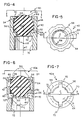
- the composite device 40 includes a hollow tubular body 42, a round elastomer element 44 in the form of a spherical ball press fitted therein, and a seat structure 46 capturing and retaining the element 44 therein. Similar to the seat structure 22 on the body 16, the seat structure 46 on the body 42 is defined by a pair of axially spaced inner and outer ribs 48, 50 integrally formed internally of the body 42 at its one end 52 and defining a recess 54 therebetween.
- the ribs 48, 50 on the body 42 have respective annular surface edges 56, 58 which engage the elastomer element 44.
- the edge 56 on the inner rib 48 is defined at the intersection of an annular side surface 60 on the rib 48 which bounds one side of the recess 54 and an annular cylindrical surface 62 on the rib 48 which faces toward the central axis C of the body 42.
- the edge 58 on the outer rib 50 is defined at the intersection of an annular side surface 66 on the rib 50 which bounds an opposite side of the recess 54 and an inwardly and downwardly tapered surface 68 on the rib 50.
- Figs. 6 and 7 illustrate a third embodiment of the composite tubular device of the present invention, generally designated 40A, whose structural features (with the exception of one) are identical to those of the second embodiment of Figs. 4 and 5 and so are identified by the same reference numerals.
- the one structural feature not present in the device 40 of second embodiment is a plurality of grooves 70 defined in the device 40A of the third embodiment.
- the grooves 70 are formed internally therein along approximately one-half the length of the body 42 which is coextensive with the one end 52 of the body having the seat structure 46 integrally formed thereon.
- Each of the grooves 70 opens toward the central axis C of the body 42, intersects and cuts through the ribs 48, 50 and extends generally parallel to the body central axis C. Since the central bore 72 of the body 42 is blocked by the elastomer element 44 captured and retained by the ribs 48, 50 of the seat structure 46, each groove 70 being in communication with the central bore 72 and the exterior of the body 42 at the one end 52 thereof defines a passage bypassing the elastomer element 44 allowing flow of fluids past the element as depicted by the arrows in Fig. 6.
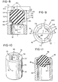
- Figs. 8-10 illustrate a fourth embodiment of the composite tubular device of the present invention, generally designated 40B, whose structural features (with the exception of one) are identical to those of the second and third embodiments of Figs. 4-5 and 6-7 and so are identified by the same reference numerals.
- the one structural feature of the device 40B which is absent from device 10 but only slightly different from the grooves 70 of the device 40A is a plurality of slots 74 defined in the device 40B of the fourth embodiment.
- the slots 74 are formed internally therein along approximately one-half the length of the body 42 which is coextensive with the one end 52 of the body having the seat structure 46 integrally formed thereon. Each of the slots 74 opens both toward the central axis C of the body 42 and away therefrom at the exterior of the body 42, and intersects with and cuts through the ribs 48, 50. Also, each slot 74 extends generally parallel to the central axis C of the body 42 and defines a passage bypassing the elastomer element 44 captured by the seat structure 46.
- Fig. 11 shows a fifth preferred embodiment of the invention wherein a hollow body 80 has an annular, inwardly projecting rib 82 projecting inwardly and cooperating with a split ring 84 received in an annular groove 86 to capture a ball 88.
- ring 84 functions similarly to the rib 24 of the embodiment of Figs. 1-3.
Landscapes
- Engineering & Computer Science (AREA)
- General Engineering & Computer Science (AREA)
- Mechanical Engineering (AREA)
- Check Valves (AREA)
- Shaping Of Tube Ends By Bending Or Straightening (AREA)
- Lift Valve (AREA)
Applications Claiming Priority (2)
| Application Number | Priority Date | Filing Date | Title |
|---|---|---|---|
| US129017 | 1987-12-04 | ||
| US07/129,017 US4970484A (en) | 1987-12-04 | 1987-12-04 | Composite elastomer-tipped tubular metallic device for armature and needle valve applications |
Publications (3)
| Publication Number | Publication Date |
|---|---|
| EP0321129A2 true EP0321129A2 (de) | 1989-06-21 |
| EP0321129A3 EP0321129A3 (en) | 1990-08-29 |
| EP0321129B1 EP0321129B1 (de) | 1994-07-20 |
Family
ID=22438094
Family Applications (1)
| Application Number | Title | Priority Date | Filing Date |
|---|---|---|---|
| EP88311452A Expired - Lifetime EP0321129B1 (de) | 1987-12-04 | 1988-12-02 | Rohrförmige, metallische Vorrichtung einer Spitze aus zusammengesetztem Elastomer für Armaturen und Nadelventile |
Country Status (5)
| Country | Link |
|---|---|
| US (1) | US4970484A (de) |
| EP (1) | EP0321129B1 (de) |
| JP (1) | JPH01206024A (de) |
| CA (1) | CA1294662C (de) |
| DE (1) | DE3850756T2 (de) |
Cited By (6)
| Publication number | Priority date | Publication date | Assignee | Title |
|---|---|---|---|---|
| EP0907045A1 (de) * | 1997-10-02 | 1999-04-07 | Giorgio Scanferla | Ventilanordnung für Heizsysteme und Wasserheizgeräte und Verfahren zu ihrer Herstellung |
| WO2006088553A1 (en) * | 2005-02-16 | 2006-08-24 | Bendix Commercial Vehicle Systems Llc | Solenoid armature with integrated spherical soft seal |
| WO2007073961A1 (de) * | 2005-12-22 | 2007-07-05 | Robert Bosch Gmbh | Elektromagnetisch betätigbares ventil |
| US7354118B2 (en) | 2005-02-25 | 2008-04-08 | Bendix Commercial Vehicle Systems, Inc. | Control valve system |
| US8794715B2 (en) | 2003-02-24 | 2014-08-05 | Bendix Commercial Vehicle Systems Llc | Electro-pneumatic latching valve system |
| WO2017196295A1 (en) * | 2016-05-09 | 2017-11-16 | Cummins Inc. | Pressure regulator plunger with an integrated check valve |
Families Citing this family (4)
| Publication number | Priority date | Publication date | Assignee | Title |
|---|---|---|---|---|
| ATE321081T1 (de) | 1999-03-12 | 2006-04-15 | Wasserlösliche oder wasserdispergierbare polymere salze | |
| DE102005033476A1 (de) * | 2005-07-18 | 2007-01-25 | Epcos Ag | Kondensatorgehäuse |
| US9062928B2 (en) | 2009-11-16 | 2015-06-23 | Thomas Appleton | Pneumatic toy gun for shooting soft balls and nozzle therefor |
| CA2685644A1 (en) * | 2009-11-16 | 2011-05-16 | Thomas Appleton | Toy gun for shooting soft balls |
Family Cites Families (13)
| Publication number | Priority date | Publication date | Assignee | Title |
|---|---|---|---|---|
| US586038A (en) * | 1897-07-06 | Bottle and stopper | ||
| US1420306A (en) * | 1921-03-08 | 1922-06-20 | Frank A Cigol | Method of painting rubber balls and the like |
| GB453489A (en) * | 1935-03-09 | 1936-09-09 | John Wilkinson Onions | Improvements in or relating to ball valve seatings |
| US2364107A (en) * | 1943-06-03 | 1944-12-05 | Irving Svirsky | Silent screwless valve plug |
| US2505428A (en) * | 1947-03-31 | 1950-04-25 | James K Pope | Air gun projectile holder |
| GB668055A (en) * | 1950-08-08 | 1952-03-12 | Flexibox Ltd | Improvements relating to stop valves |
| US2839078A (en) * | 1953-07-03 | 1958-06-17 | Pantex Mfg Corp | Relief valve |
| US3529805A (en) * | 1968-10-11 | 1970-09-22 | Whitey Research Tool Co | Ball valve |
| US3559325A (en) * | 1969-01-16 | 1971-02-02 | John Webster | Gas noisemaker |
| DE2134067A1 (de) * | 1971-07-08 | 1973-01-25 | Servo Technik Gmbh | Elektromagnetisches ventil |
| ES445020A1 (es) * | 1976-02-10 | 1977-06-01 | Bendiberica Sa | Perfeccionamientos en valvulas de limitacion de presion. |
| US4368754A (en) * | 1980-09-23 | 1983-01-18 | Jamaica Manufacturing (Canada) Co., Ltd. | Washerless valve structure particularly for faucets |
| US4525910A (en) * | 1983-08-08 | 1985-07-02 | Vernay Laboratories, Inc. | Resilient tipped needle valve |
-
1987
- 1987-12-04 US US07/129,017 patent/US4970484A/en not_active Expired - Fee Related
-
1988
- 1988-12-02 DE DE3850756T patent/DE3850756T2/de not_active Expired - Fee Related
- 1988-12-02 EP EP88311452A patent/EP0321129B1/de not_active Expired - Lifetime
- 1988-12-02 CA CA000584917A patent/CA1294662C/en not_active Expired - Lifetime
- 1988-12-05 JP JP63307685A patent/JPH01206024A/ja active Pending
Cited By (12)
| Publication number | Priority date | Publication date | Assignee | Title |
|---|---|---|---|---|
| EP0907045A1 (de) * | 1997-10-02 | 1999-04-07 | Giorgio Scanferla | Ventilanordnung für Heizsysteme und Wasserheizgeräte und Verfahren zu ihrer Herstellung |
| US8794715B2 (en) | 2003-02-24 | 2014-08-05 | Bendix Commercial Vehicle Systems Llc | Electro-pneumatic latching valve system |
| WO2006088553A1 (en) * | 2005-02-16 | 2006-08-24 | Bendix Commercial Vehicle Systems Llc | Solenoid armature with integrated spherical soft seal |
| US7367636B2 (en) | 2005-02-16 | 2008-05-06 | Bendix Commercial Vehicle Systems, Llc | Solenoid armature with integrated spherical soft seal |
| CN101119878B (zh) * | 2005-02-16 | 2011-04-13 | 奔迪士商业运输系统公司 | 车辆气压系统的螺线管阀、车辆的制动和停车系统、控制气压系统调整器内压缩气流的方法 |
| AU2005327483B2 (en) * | 2005-02-16 | 2011-09-15 | Bendix Commercial Vehicle Systems Llc | Solenoid armature with integrated spherical soft seal |
| US7354118B2 (en) | 2005-02-25 | 2008-04-08 | Bendix Commercial Vehicle Systems, Inc. | Control valve system |
| US8136893B2 (en) | 2005-02-25 | 2012-03-20 | Bendix Commerical Vehicle Systems Llc | Control valve system |
| US8851580B2 (en) | 2005-02-25 | 2014-10-07 | Bendix Commerical Vehicle Systems Llc | Control valve system |
| WO2007073961A1 (de) * | 2005-12-22 | 2007-07-05 | Robert Bosch Gmbh | Elektromagnetisch betätigbares ventil |
| US8313084B2 (en) | 2005-12-22 | 2012-11-20 | Robert Bosch Gmbh | Electromagnetically operatable valve |
| WO2017196295A1 (en) * | 2016-05-09 | 2017-11-16 | Cummins Inc. | Pressure regulator plunger with an integrated check valve |
Also Published As
| Publication number | Publication date |
|---|---|
| EP0321129A3 (en) | 1990-08-29 |
| JPH01206024A (ja) | 1989-08-18 |
| DE3850756D1 (de) | 1994-08-25 |
| US4970484A (en) | 1990-11-13 |
| DE3850756T2 (de) | 1994-10-27 |
| EP0321129B1 (de) | 1994-07-20 |
| CA1294662C (en) | 1992-01-21 |
Similar Documents
| Publication | Publication Date | Title |
|---|---|---|
| US4970484A (en) | Composite elastomer-tipped tubular metallic device for armature and needle valve applications | |
| US5358420A (en) | Pressure relief for an electrical connector | |
| US4781213A (en) | Ball check valve | |
| USRE41182E1 (en) | Sealed pass-through electrical connector | |
| US4828297A (en) | Fluid coupling | |
| US4360326A (en) | Oil lubricated vacuum pump including an oil separator disposed adjacent of its suction opening | |
| KR20130049738A (ko) | 체크 밸브 | |
| KR880007953A (ko) | 체크 밸브 | |
| US5064359A (en) | Annular support for a seal for a tilt piston | |
| US4537524A (en) | Ball and socket joint | |
| JP3287445B2 (ja) | 2サイクルエンジンの分離潤滑用オイルポンプのニップル | |
| US4429906A (en) | Female element for quick-coupling connection for flexible pipes | |
| US4590819A (en) | Motion transmitting remote control assembly molded terminal connector | |
| JPH09509728A (ja) | 逆止弁 | |
| EP0176687A2 (de) | Dichteinrichtung für Drosselklappen | |
| EP0809028A2 (de) | Pumpenmembran | |
| US2856025A (en) | Grease fitting | |
| JPH049492Y2 (de) | ||
| JPH055389U (ja) | フローテイングハンド | |
| US5002018A (en) | Umbrella seal for an automobile valve stem | |
| US5002835A (en) | Armature insert | |
| WO1986000680A1 (en) | Ball valve and method of mounting such valve | |
| GB2112448A (en) | Ball and socket joints | |
| JP2007255652A (ja) | シールリングおよびシールリング製造方法 | |
| JPS6020801Y2 (ja) | 流体圧シリンダ用ピストン装置 |
Legal Events
| Date | Code | Title | Description |
|---|---|---|---|
| PUAI | Public reference made under article 153(3) epc to a published international application that has entered the european phase |
Free format text: ORIGINAL CODE: 0009012 |
|
| AK | Designated contracting states |
Kind code of ref document: A2 Designated state(s): DE ES FR GB IT NL SE |
|
| PUAL | Search report despatched |
Free format text: ORIGINAL CODE: 0009013 |
|
| AK | Designated contracting states |
Kind code of ref document: A3 Designated state(s): DE ES FR GB IT NL SE |
|
| 17P | Request for examination filed |
Effective date: 19901222 |
|
| 17Q | First examination report despatched |
Effective date: 19921014 |
|
| GRAA | (expected) grant |
Free format text: ORIGINAL CODE: 0009210 |
|
| AK | Designated contracting states |
Kind code of ref document: B1 Designated state(s): DE ES FR GB IT NL SE |
|
| PG25 | Lapsed in a contracting state [announced via postgrant information from national office to epo] |
Ref country code: NL Effective date: 19940720 Ref country code: ES Free format text: THE PATENT HAS BEEN ANNULLED BY A DECISION OF A NATIONAL AUTHORITY Effective date: 19940720 |
|
| ET | Fr: translation filed | ||
| REF | Corresponds to: |
Ref document number: 3850756 Country of ref document: DE Date of ref document: 19940825 |
|
| ITF | It: translation for a ep patent filed | ||
| PG25 | Lapsed in a contracting state [announced via postgrant information from national office to epo] |
Ref country code: SE Effective date: 19941020 |
|
| NLV1 | Nl: lapsed or annulled due to failure to fulfill the requirements of art. 29p and 29m of the patents act | ||
| PLBE | No opposition filed within time limit |
Free format text: ORIGINAL CODE: 0009261 |
|
| STAA | Information on the status of an ep patent application or granted ep patent |
Free format text: STATUS: NO OPPOSITION FILED WITHIN TIME LIMIT |
|
| 26N | No opposition filed | ||
| PGFP | Annual fee paid to national office [announced via postgrant information from national office to epo] |
Ref country code: GB Payment date: 19951130 Year of fee payment: 8 |
|
| PGFP | Annual fee paid to national office [announced via postgrant information from national office to epo] |
Ref country code: FR Payment date: 19951215 Year of fee payment: 8 |
|
| PGFP | Annual fee paid to national office [announced via postgrant information from national office to epo] |
Ref country code: DE Payment date: 19951219 Year of fee payment: 8 |
|
| PG25 | Lapsed in a contracting state [announced via postgrant information from national office to epo] |
Ref country code: GB Effective date: 19961202 |
|
| GBPC | Gb: european patent ceased through non-payment of renewal fee |
Effective date: 19961202 |
|
| PG25 | Lapsed in a contracting state [announced via postgrant information from national office to epo] |
Ref country code: FR Effective date: 19970829 |
|
| PG25 | Lapsed in a contracting state [announced via postgrant information from national office to epo] |
Ref country code: DE Effective date: 19970902 |
|
| REG | Reference to a national code |
Ref country code: FR Ref legal event code: ST |
|
| PG25 | Lapsed in a contracting state [announced via postgrant information from national office to epo] |
Ref country code: IT Free format text: LAPSE BECAUSE OF NON-PAYMENT OF DUE FEES Effective date: 20051202 |